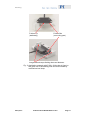
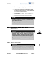
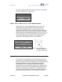
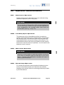
1
MP97E User Manual P-661/U-164.01 PILine® OEM Piezo Linear Motors Release: 1.0.0 Date: 2009-05-05 This document describes the following product(s): P-661 PILine® OEM Piezo Linear Motor, 2 N push/pull force U-164.01 PILine® OEM Piezo Linear Motor, 4 N push/pull force © Physik Instrumente (PI) GmbH & Co. KG Auf der Römerstr. 1 ⋅ 76228 Karlsruhe, Germany Tel. +49 721 4846-0 ⋅ Fax: +49 721 4846-299 [email protected] ⋅ www.pi.ws Manufacturer's Declaration according to Appendix II B of 98/37/EG Machinery Directive (Partly Completed Machinery) Manufacturer: Physik Instrumente (PI) GmbH & Co. KG Manufacturer´s Auf der Römerstrasse 1 D-76228 Karlsruhe, Germany Address: The manufacturer hereby declares that the product Product Name: Model Numbers: Product Options: PILine® OEM Piezo Linear Motors P-661, U-164.01 all complies with the following European directives: 98/37/EC, Machinery Directive The applied standards certifying the conformity are listed below. Safety of Machinery: EN 12100 The manufacturer hereby declares that P-661 and U-164.01 must not be operated until the machinery in which it is to be integrated complies with the requirements of 98/37/EC Machinery Directive. April 27, 2009 Karlsruhe, Germany Dr. Karl Spanner President Declaration of Conformity according to DIN EN ISO / IEC 17050: 2005-01 Manufacturer: Physik Instrumente (PI) GmbH & Co. KG Manufacturer´s Address: Auf der Römerstrasse 1 D-76228 Karlsruhe, Germany The manufacturer hereby declares that the product Product Name: Model Numbers: Product Options: PILine® OEM Piezo Linear Motors P-661, U-164.01 all complies with the following European directives: 2006/95/EC, Low-voltage directive (LVD) 2004/108/EC, EMC Directive The applied standards certifying the conformity are listed below. Electromagnetic Emission: EN 61000-6-3, EN 55011 Electromagnetic Immunity: EN 61000-6-1 Safety (Low Voltage Directive): EN 61010-1 April 27, 2009 Karlsruhe, Germany Dr. Karl Spanner President Physik Instrumente (PI) GmbH & Co. KG is the owner of the following company names and trademarks: PI®, PIC®, PICMA®, PILine®, PIFOC®, PiezoWalk®, NEXACT®, NEXLINE®, NanoCube®, NanoAutomation® The products described in this manual are in part protected by the following patents: US-patent No. 6,765,335 Copyright 1999–2009 by Physik Instrumente (PI) GmbH & Co. KG, Karlsruhe, Germany. The text, photographs and drawings in this manual enjoy copyright protection. With regard thereto, Physik Instrumente (PI) GmbH & Co. KG reserves all rights. Use of said text, photographs and drawings is permitted only in part and only upon citation of the source. First printing 2009-05-05 Document Number MP97E, KSch, Release 1.0.0 P-661_U-164_User_MP97E100.doc Subject to change without notice. This manual is superseded by any new release. The newest release is available for download at www.pi.ws. About this Document Users of this Manual This manual is designed to help the reader to install and operate the P-661/U-164.01 PILine® OEM Piezo Linear Motors. It assumes that the reader has a fundamental understanding of micropositioning systems and applicable safety procedures. The manual describes the physical specifications and dimensions of the P-661/U-164.01 PILine® OEM Piezo Linear Motors as well as the installation procedures which are required to put the associated positioning system into operation. This document is available as PDF file. The newest release is available for download at www.pi.ws or via email: contact your PI Sales Engineer or write [email protected]. Conventions The notes and symbols used in this manual have the following meanings: WARNING Calls attention to a procedure, practice or condition which, if not correctly performed or adhered to, could result in injury or death. DANGER Indicates the presence of high voltage (> 50 V). Calls attention to a procedure, practice or condition which, if not correctly performed or adhered to, could result in injury or death. CAUTION Calls attention to a procedure, practice, or condition which, if not correctly performed or adhered to, could result in damage to equipment. NOTE Provides additional information or application hints. Related Documents The driver electronics which is required to operate P-661/U-164.01 PILine® OEM Piezo Linear Motors is described in separate manuals. All documents are available as PDF files. Updated releases are available for download at www.pi.ws or via email: contact your Physik Instrumente sales engineer or write [email protected]. ! Contents 1 Introduction 1.1 1.2 1.3 Safety Precautions .....................................................................4 Unpacking ..................................................................................6 System Components ..................................................................7 1.3.1 1.3.2 1.3.3 2 2.3 Materials and Preparations ...................................................... 12 How to proceed ........................................................................ 13 Mounting the Piezoelectric Actuator.........................................14 2.3.1 2.3.2 P-661.P01 Actuator Mounting .................................................. 14 U-164.01 Actuator Mounting .................................................... 15 Operating 3.1 3.2 3.3 General Information ................................................................. 18 OEM Drive Electronics Board .................................................. 19 Drive Electronics with LEMO Socket ....................................... 20 Run-In of the Motor ..................................................................20 Application Recommendations.................................................22 3.5.1 3.5.2 3.5.3 3.5.4 3.6 17 General Notes ..........................................................................17 Initial Operation ........................................................................17 Connecting Motor and Drive Electronics ..................................18 3.3.1 3.3.2 3.3.3 3.4 3.5 9 Designing the Moving System....................................................9 Fixing the Friction Bar ..............................................................12 2.2.1 2.2.2 3 Standard Components ............................................................... 7 Friction Bar ................................................................................. 7 Drive Electronics ........................................................................ 8 Mounting 2.1 2.2 3 Continuous Operation .............................................................. 22 Low-Duty-Cycle Operation ....................................................... 22 Open-Loop Operation .............................................................. 22 Closed-Loop Operation ............................................................ 22 Maintenance.............................................................................23 4 Old Equipment Disposal 24 5 Technical Data 25 5.1 5.2 Specifications ...........................................................................25 Motor Performance...................................................................26 5.2.1 5.2.2 5.3 Velocity and Dynamic Force .................................................... 26 Impact of Off-Time and Temperature....................................... 27 Dimensions ..............................................................................28 Contents 5.3.1 5.3.2 P-661.P01 ................................................................................ 28 U-164.01................................................................................... 29 Introduction 1 Introduction PILine® OEM piezo linear motors are designed to be used as drive units in linear positioning stages. At the heart of the patented ultrasonic drive is a piezoceramic plate which is excited to produce high-frequency eigenmode oscillations. A friction tip attached to the plate moves along an inclined linear path at an eigenmode frequency. Through its contact with the friction bar, it drives the moving part of the mechanics forward or backwards. With each oscillatory cycle, the mechanics executes a step of a few nanometers; the macroscopic result is a smooth motion with a virtually unlimited travel range. Because the ceramic plate with the friction tip is pressed against the friction bar, holding forces are generated even when the motor is at rest. A typical open-loop motion system with a P-661 or a U-164.01 is set up as shown in the example in Fig. 1: c Custom stage with integrated P-661 or U-164.01 OEM motor and friction bar d Drive electronics with external power supply; excites the piezoceramic plate in the actuator e 3rd party device, provides the control signals for the drive electronics Fig. 1: System configuration with PILine® OEM piezo linear motor (integrated in a custom stage) and PI’s C-184 OEM driver. For closed-loop operation external position feedback devices such as incremental encoders and an external controller are required (not included). www.pi.ws P-661/U-164.01 MP97E Release 1.0.0 Page 3 Introduction Features: 1.1 Small High-Speed Linear Motor Patented Principle Features High Holding Forces Velocity to 500 mm/s Acceleration to 15 g Minimum Incremental Motion to 0.05 μm Self-Locking with up to 4 N Safety Precautions WARNING When mounting the motor follow the instructions in this manual and take appropriate measures to conform to the safety requirements published by international standards. DANGER The P-661 respectively U-164.01 PILine® piezo motor does not contain any user-serviceable parts. Do not remove the cover of the motor. Never re-assemble the motor. Hazardous voltage can be present on the motor components. DANGER Do not make electrical contact with the conductors in the connecting cables. PILine® motors are driven by piezoelectric actuators which require hazardous voltages. When removing the connectors from the drive electronics, the piezoelectric actuator in the motor can stay charged for several hours. Therefore short-circuit pins Piezo1, Piezo2 and Piezo3 of the LEMO connector (Fig. 7, p. 20) by connecting them to ground. Temperature changes can also induce charges on the piezoelectric actuator. www.pi.ws P-661/U-164.01 MP97E Release 1.0.0 Page 4 Introduction ! CAUTION ! CAUTION ! CAUTION Install and operate the P-661 respectively U-164.01 PILine® motor only when you have read the operating instructions. Keep the instructions readily available close to the device in a safe place. When the instructions are lost or have become unusable, ask the manufacturer for a new copy. Add all information given by the manufacturer to the instructions, e.g. supplements or Technical Notes. Make sure the friction tip rides completely on the friction bar throughout the motor’s complete path of travel. Otherwise the motor could be permanently damaged. Do not lubricate the bearing with grease. All components of the mechanics must be free from dust, oil and grease. Otherwise the performance of the motor will be severely limited. ! CAUTION ! CAUTION Use only the wires provided by PI for interconnecting motor and drive electronics. Do not extend or shorten the wire length since this will affect the performance of the motor and can cause damage to the drive electronics. Do not excite the piezoelectric actuator unless the motor is mounted and preloaded. CAUTION ! Do not operate at full power for 100% of the operating time as the motor may overheat. During continuous operation, the average power level must not exceed 80% (see Fig. 11 on p. 27). www.pi.ws P-661/U-164.01 MP97E Release 1.0.0 Page 5 Introduction CAUTION The P-661 produces a heat dissipation of up to 5 W, the U-164.01 produces up to 10 W heat dissipation which might disturb your application. CAUTION Adjust the control signal for open-loop systems so that the motor does not abruptly reach the end stop or try to move past it, because this significantly increases the wear of friction tip and friction bar. CAUTION Although the piezomotor is theoretically soundless, you will encounter an operation noise up to 50 dB(A). Keep in mind that the P-661 and the U-164.01 are ultrasonic devices — you will receive higher noise levels even at frequencies between 100 and 500 kHz. 1.2 Unpacking Unpack the P-661 respectively U-164.01 with care. Check the contents against the bill of sale and the packing list. Inspect the contents for signs of damage. If parts are missing or you notice signs of damage, please contact PI immediately. Save all packing materials in the event the product need be shipped back to PI or elsewhere. www.pi.ws P-661/U-164.01 MP97E Release 1.0.0 Page 6 ! ! ! Introduction 1.3 System Components To operate PILine® P-661 respectively U-164.01 OEM piezo linear motors, in addition to the piezoelectric motor itself, a friction bar – or a ceramic ring for rotatory applications - and drive electronics are required. Since the length of the friction bar and the choice of the drive electronics depend on the application, both items are not included as standard components but must be ordered separately. 1.3.1 Standard Components The following components are always included: PILine® OEM Piezo Linear Motor (piezoelectric actuator with wires): P-661.P01 or U-164.01 Screw set for mounting: order# 4230 for P-661.P01 order# 000025687 for U-164.01 1.3.2 Adjust gauge 0.5 mm, polystyrene, order# M661E0040 MP97E User Manual for P-661/U-164.01 (this document) in printed form Friction Bar One of the following friction bars must be ordered separately. Friction bars for P-661.P01: www.pi.ws Order# Length x Width x Thickness P-661.B01 15 x 3.5 x 0.5 mm P-661.B02 25 x 3.5 x 0.5 mm P-661.B05 55 x 3.5 x 0.5 mm P-661/U-164.01 MP97E Release 1.0.0 Page 7 Introduction Friction bars for U-164.01: Order# Length x Width x Thickness P-664.B01 15 x 5 x 0.5 mm P-664.B02 25 x 5 x 0.5 mm P-664.B05 55 x 5 x 0.5 mm All friction bars are made of Al2O3 ceramics. 1.3.3 Drive Electronics One of the following drive electronics must be ordered separately. For P-661.P01: Order# Type C-184.161 Analog OEM drive electronics C-185.161 Analog drive electronics box, with power supply For U-164.01: Order# Type C-184.164 Analog OEM drive electronics C-185.164 Analog drive electronics box, with power supply The C-184 and C-185 drive electronics convert an analog control signal into the voltage which excites the ultrasonic oscillation of the piezoelectric actuator. Analog control permits continuously adjusting the output power and thus the velocity of the motor. The required 10-volt-range, differential control signal corresponds to the analog output of standard DC-motor controllers from different manufacturers such as GALIL, NI or DeltaTau, which also provide special options for piezo linear motors. All drive electronics are described in their own manuals. www.pi.ws P-661/U-164.01 MP97E Release 1.0.0 Page 8 Mounting 2 Mounting Mounting PILine® piezo linear motors comprises the following steps, which are described in this section: 2.1 1 Designing the moving system (p. 9) 2 Fixing the friction bar (p. 12) 3 Mounting the piezoelectric actuator (p. 13) Designing the Moving System CAUTION ! Make sure the friction tip rides completely on the friction bar throughout the motor’s complete path of travel. Otherwise the motor could be permanently damaged. CAUTION ! Do not lubricate the bearing with grease. All components of the mechanics must be free from dust, oil and grease. Otherwise the performance of the motor will be severely limited. CAUTION ! Do not extend or shorten the wire length since this will affect the performance of the motor and can cause damage to the drive electronics. The dimensions and the hole pattern for mounting are provided by the drawings on p. 28 and p. 29. Friction bar or piezoelectric actuator (and cables) can be on the moving part of the mechanics. For optimum performance the design of your mechanics should comply with the following recommendations: www.pi.ws If the friction bar becomes contaminated with dust, oil, grease or condensed water, the motor will show an instant drop in dynamic force and speed. It is therefore P-661/U-164.01 MP97E Release 1.0.0 Page 9 Mounting recommended to enclose the entire system and to avoid changes in ambient temperature. www.pi.ws Actuator portion and friction bar must be mounted on an even, rigid surface with high stiffness to avoid torsion of the basic profiles. The friction tip must be perpendicular to the friction bar, and the proper distance/pressure between them must be maintained over the entire travel range. Do not use cantilevers for mounting. Limit the travel distance using mechanical end stops. Ideally the end stops are integrated in the mounting surface (see figures below). High quality linear bearings especially suitable for high precision applications are recommended. This might be cross roller bearings or ball bearings. Vertical mounting: When turned off, the piezomotor can bear a vertical force Fh due to its intrinsic friction: P-661: Fh = 1.5 N (at least) U-164.01: Fh = 3 N (at least) In a typical industrial application the components of Fh are the gravitational force (Fg = m·g) and vibration force (Fv = m· ∫ f²·A(f) df). P-661/U-164.01 MP97E Release 1.0.0 Page 10 Mounting Friction Tip (stationary) Friction Bar (on moving part) Integrated end stops limiting the travel distance Fig. 2: Application example with P-661; friction bar is fixed on the guide rail of the bearing and should be limited by mechanical end stops www.pi.ws P-661/U-164.01 MP97E Release 1.0.0 Page 11 Mounting 2.2 Fixing the Friction Bar NOTES The length of the friction bar should not exceed the length of the element on which it is to be fixed. Make sure this element is solid and even along all the length of the friction bar to prevent it from breaking when the friction tip of the piezoelectric actuator is pressed against. Make sure that the points where the friction bar is affixed with two-component adhesive are outside the range where the friction tip rides on the friction bar, e.g. using mechanical end stops. 2.2.1 Materials and Preparations To fix the friction bar on the mounting surface, we recommend the following two-component adhesive: UHU Plus Endfest Wherever applicable, it is a good idea to prepare the mounting surface so that the friction bar is placed in a slot of 0.5 mm depth (see Fig. 3). P-661.P01: W = 3.6 + 0.1 mm U-164.01: W = 5.1 + 0.1 mm Fig. 3: Slot for the friction bar, dimensions in mm www.pi.ws P-661/U-164.01 MP97E Release 1.0.0 Page 12 Mounting 2.2.2 How to proceed To affix the friction bar proceed as follows: 1 Degrease the mounting surface and the friction bar with acetone. If the mounting surface is located at the moving part of your system, make sure that acetone does not enter the bearing. 2 Mix the two component adhesive according to the manufacturer specifications. NOTE Make sure that adhesive does not contact the front surface of the friction bar. 3 Place a drop of adhesive at the positions 1 and 2. 1 4 2 Affix the friction bar on the mounting surface: Remove the protective film from the adhesive tape and press the friction bar against the surface. If you, for example, affix the friction bar on the guide rail of a bearing, it is recommended to place the bearing on an even surface oriented as shown in the figure below. Both the bearing and the friction bar can then be adjusted on each other using the even surface. Friction Bar 5 www.pi.ws Guide rail Let the adhesive cure according to the manufacturer specifications. The curing times for UHU Plus Endfest are listed in the table below. P-661/U-164.01 MP97E Release 1.0.0 Page 13 Mounting Temperature 20°C 40°C 70°C 100°C 180°C 2.3 Curing time 12 h 3h 40 min 10 min 5 min Strength after curing 1200 N/cm² 1800 N/cm² 2000 N/cm² 2500 N/cm² 3000 N/cm² Mounting the Piezoelectric Actuator NOTE Keep in mind that the housing of the piezoelectric actuator has to be perpendicular to the friction bar over the entire travel range to maintain the proper distance/pressure between friction tip and friction bar. 2.3.1 P-661.P01 Actuator Mounting NOTES Mount the actuator only with its bottom surface lying on the mounting base (as shown in Fig. 4). It is recommended to use the M2x8 mounting screws which come with the piezoelectric actuator. 1. Provide the mounting surface for the piezoelectric actuator with mounting holes according to the hole pattern given in the drawing on p. 28. For mounting the actuator you can use either a) its elongated holes—when you want to insert the mounting screws from the top or b) www.pi.ws its threaded holes (M2)—when the mounting screws are to be inserted from the bottom. In this case the mounting surface should be provided with elongated holes. P-661/U-164.01 MP97E Release 1.0.0 Page 14 Mounting Fig. 4. Mounting holes on P-661 piezoelectric actuator 2.3.2 2. Mount the piezoelectric actuator without tightening the mounting screws completely. 3. Adjust the position of the piezoelectric actuator to achieve the required preload: 3.1 Place the 0.5 mm adjust gauge (comes with the motor) between the housing of the piezoelectric actuator and the friction bar, so that the friction tip is located in the gap of the gauge. 3.2 Press the piezoelectric actuator gently in the direction of the friction bar until there is no free space left between the actuator housing, the adjust gauge and the friction bar, and tighten the screws lightly. Then remove the adjust gauge. 3.3 Fully tighten the screws. U-164.01 Actuator Mounting 1. Provide the mounting surface for the piezoelectric actuator with mounting holes according to the hole pattern given in the drawing on p. 29. CAUTION ! The length of the friction tip given on p. 29 is valid when the motor is mounted and preloaded. For ease of mounting, it is strongly recommended to provide 1 mm of additional space between friction bar and motor housing. www.pi.ws P-661/U-164.01 MP97E Release 1.0.0 Page 15 Mounting Three holes are provided for actuator mounting. Use the included M2.5x10 torx pan head screws to fix the piezo motor to your mounting platform. Fig. 5. Mounting holes on U-164.01 piezoelectric actuator, top view 2. Adjust the position of the piezoelectric actuator to achieve the required preload: a) with adjust gauge: 1. Place the 0.5 mm adjust gauge (comes with the motor) between the housing of the piezoelectric actuator and the friction bar, so that the friction tip is located in the gap of the gauge 2. Press the piezoelectric actuator gently in the direction of the friction bar until there is no free space left between the actuator housing, the adjust gauge and the friction bar, and tighten the screws lightly. Then remove the adjust gauge. 3. Fully tighten the screws. or: b) without adjust gauge, here you need a stop on your mounting platform 1. Push the housing of the piezoelectric actuator against the stop of your mounting platform. 2. Fully tighten the screws. www.pi.ws P-661/U-164.01 MP97E Release 1.0.0 Page 16 Operating 3 Operating 3.1 General Notes CAUTION ! PILine® piezo linear motors and drive electronics should be operated in clean environments. Protect the units against dust, oil, grease and liquid spray. If the friction bar becomes contaminated with dust, oil, grease or condensed water, the motor will show an instant drop in dynamic force and speed. ! CAUTION ! CAUTION The P-661 produces a heat dissipation of up to 5 W, the U-164.01 produces up to 10 W which might disturb your application. Although the piezomotor is theoretically soundless, you will encounter an operation noise up to 50 dB(A). Keep in mind that the P-661 respectively U-164.01 is an ultrasonic device – you will receive higher noise levels even at frequencies between 100 and 500 kHz. See "Motor Performance" Section on p. 26 for further information on operational conditions. 3.2 Initial Operation Initial operation of your PILine® piezo linear motor involves the following steps: www.pi.ws 1 Integrate the motor (piezoelectric actuator, friction bar and external bearing) into your application. Follow the instructions in Section 2, p. 9. 2 Provide for the control signals required to operate the system—see the User Manual of your drive electronics for details. P-661/U-164.01 MP97E Release 1.0.0 Page 17 Operating 3 Connect the motor to the drive electronics. Follow the instructions in Section 3.3, p. 18. 4 Tune the drive electronics to the mechanics to obtain the optimal excitation frequency – see the User Manual of your drive electronics for details. 5 Run the motor in for approx. 1 hour. See Section 3.4, p. 20 for details. 6 Repeat the frequency tuning described in Step 4. NOTES Operate the motor only if mounting is completed (preload force is applied, see p. 9ff). Tuning must be repeated when the friction bar or the actuator are disturbed or remounted and / or the drive electronics is replaced. 3.3 Connecting Motor and Drive Electronics DANGER Do not make electrical contact with the conductors in the connecting cables. PILine® motors are driven by piezoelectric actuators which require hazardous voltages. Therefore short-circuit pins Piezo1, Piezo2 and Piezo3 of the LEMO connector (Fig. 7, p. 20) by connecting them to ground. Temperature changes can also induce charges on the piezoelectric actuator. 3.3.1 General Information CAUTION Use only the wires provided by PI for interconnecting motor and drive electronics. Do not extend or shorten the wire length since this will affect the performance of the motor and can cause damage to the drive electronics. www.pi.ws P-661/U-164.01 MP97E Release 1.0.0 Page 18 ! Operating If you need special wire lengths, consult your Physik Instrumente sales engineer or write [email protected]. Provided that the piezoelectric actuator with the friction tip is on the stationary part of your mechanics and the friction bar is affixed on the moving part, the pin/wire assignment specified below and in the User Manual of the drive electronics causes the motion polarity shown in Fig. 6. To reverse direction of motion, interchange the yellow and the white wires of the PIline® piezo linear motor when connecting. Positive control signal* Negative control signal* – Friction bar is moving, actuator is stationary + *Control signals: Negative and Positive control signal refers to the C-184 and C-185 analog drive electronics Fig. 6: Motion direction definitions for P-661 or U-164.01 piezomotors with the wiring as specified in the drive electronics User Manual, motor top view (schematic representation) 3.3.2 OEM Drive Electronics Board The connections to a C-184.16x OEM driver board can be made in one of the following ways (depending on the application): Solder the wires from the piezoelectric actuator to the solder points on the board Attach an appropriate terminal/connector to the driver board and connect the wires from the motor to it, either directly or using an appropriate connector For the location of the solder points / connector on the driver board and for the assignment of the wires to the solder points / pins see the User Manual of your drive electronics. www.pi.ws P-661/U-164.01 MP97E Release 1.0.0 Page 19 Operating The wires of the PILine® piezo linear motor have the following functions, indicated by the wire color. Wire Color Shield Yellow White Red 3.3.3 Function GND Piezo 3 Piezo 2 Piezo 1 Drive Electronics with LEMO Socket When using a C-185.16x drive electronics box, the P-661 respectively the U-164.01 PILine® piezo linear motor is connected via a LEMO socket. Connect the Lemo 3-pin connector (FFA.0S.303.CLAC17) which comes with the drive electronics to the wires of the piezoelectric actuator as listed below to have a motion polarity as shown in Fig. 6 on p. 19. To reverse direction of motion, interchange the yellow and white wires when attaching the connector. The shield must be connected to the metal part of the Lemo connector. 3.4 Lemo Pin Signal Wire Color 1 2 3 Piezo 2 Piezo 3 Piezo 1 white yellow red Fig. 7: Lemo connector FFA.0S.303.CLAC17, pins from solder side Run-In of the Motor For maximum force generation, a PILine® piezo linear motor requires firm, even contact between a well-defined area of the friction tip and the friction bar. Depending on manufacturing and mounting tolerances, the initial contact may be irregular, consisting of a line or, worse yet, a point. By having the piezomotor move the mechanics (open-loop or closed-loop), a stable area of contact is quickly established by wearing in the friction tip. This procedure, called run-in, increases the force generation of the piezomotor. The rate of subsequent wear is also decreased, because the contact pressure is uniformly www.pi.ws P-661/U-164.01 MP97E Release 1.0.0 Page 20 Operating distributed. NOTE Before the run-in the mechanics must be completely mounted, and the drive electronics must be properly tuned (see User Manual of the drive electronics). The following conditions are required for run-in: Duty cycle: 50% Run-in procedure: 1. Move to left end of bar respecting the mechanical end stop (see Fig. 2) at approximately 70% of max. control input 2. Stop for 1 sec 3. Move to right end of bar respecting the mechanical end stop at approximately 80% of max. control input 4. Stop for 1 sec 5. Repeat this procedure Duration: approx. 20 minutes After this time the motor achieves 90% of its maximum dynamic force. The duration depends on the angular alignment of the friction tip to the friction bar. You can shorten the run-in procedure by keeping the tightest possible mounting tolerances. After run-in, the friction bar must be cleaned thoroughly using a cotton swab or a lint-free cloth soaked with alcohol or acetone. Alternatively, you can use oil-free compressed air. Do not disturb the actuator or friction bar mounting, but make sure that the cleaning agent does not enter the actuator. NOTE Run-in must be repeated if the friction bar or the actuator is disturbed or remounted. www.pi.ws P-661/U-164.01 MP97E Release 1.0.0 Page 21 Operating 3.5 Application Recommendations 3.5.1 Continuous Operation Highest dynamic force and holding force are achieved during continuous operation (100% duty cycle). CAUTION Do not operate at full power for 100% of the operating time as the motor may overheat. During continuous operation at room temperature, the average power level must not exceed 80% (see Fig. 11 on p. 27). 3.5.2 ! Low-Duty-Cycle Operation The piezomotor will not immediately achieve its maximum dynamic and holding force when operated after a rest period or with low duty cycle. This behavior results from the friction bar contamination which occurs even during a short off-time. The contamination reduces the friction grip between friction tip and friction bar for the first minute of operation. You will observe this behaviour even in vacuum. 3.5.3 Open-Loop Operation CAUTION Adjust the control signal for open-loop systems so that the motor does not abruptly reach the end stop or try to move past it, because this significantly increases the wear of friction tip and friction bar. 3.5.4 Closed-Loop Operation For closed-loop operation external position feedback devices such as incremental encoders are required (not included). Installing such devices follow the mounting guidelines provided by the manufacturer. www.pi.ws P-661/U-164.01 MP97E Release 1.0.0 Page 22 ! Operating NOTE You should mount the external feedback device as close as possible to the designed motion. 3.6 Maintenance Operating the PILine® piezo linear motors in clean environments, no maintenance is required. If you believe your unit requires maintenance, contact PI. www.pi.ws P-661/U-164.01 MP97E Release 1.0.0 Page 23 Old Equipment Disposal 4 Old Equipment Disposal In accordance with EU directive 2002 / 96 / EC (WEEE), as of 13 August 13th 2005, electrical and electronic equipment may not be disposed of in the member states of the EU mixed with other wastes. To meet the manufacturer’s product responsibility with regard to this product, Physik Instrumente (PI) GmbH & Co. KG will ensure environmentally correct disposal of old PI equipment that was first put into circulation after 13 August 13th 2005, free of charge. If you have such old equipment from PI, you can send it to the following address postage-free: Physik Instrumente (PI) GmbH & Co. KG Auf der Römerstr. 1 76228 Karlsruhe, Germany www.pi.ws P-661/U-164.01 MP97E Release 1.0.0 Page 24 Technical Data 5 Technical Data 5.1 Specifications Model P-661.P01 U-164.01 Active axes 1 1 Travel range* unlimited unlimited Min. incremental motion** *** 0.05 µm 0.05 µm Max. velocity*** 500 mm/s 500 mm/s 2 Max. acceleration*** 150 m/s 150 m/s2 Non-energized holding stiffness 0.7 N/μm ±10% 3 N/μm ±10% Min. holding force*** 1.5 N 4N Max. push/pull force*** 2N 6N Preload on friction bar 9 N ±10% 18 N ±10% Motor voltage, provided by the drive 120 Vpp, 42 Vrms electronics approx. 210 kHz 168 Vpp, 60 Vrms approx. 155 kHz Operating voltage (drive electronics) 12 V 12 V Max. electrical power (drive electronics) 5W 10 W Operating temperature range -20 to +50 °C -20 to +50 °C Humidity max. 95%; non-condensing max. 95%; non-condensing Body material aluminum, anodized aluminum, anodized Mass (w/o friction bar and drive electronics) 10 g 20 g Dimensions (w/o friction bar and drive electronics) 14 x 35 x 6 mm 24 x 44 x 9 mm Cable length 1.6 m 1.0 m Connector open end open end Recommended controller/drive electronics C-184, C-185 C-184, C-185 * The travel range of piezo linear motors is virtually unlimited and depends on the length of the friction bar, which is available separately. ** The minimum incremental motion is a typical value that can be achieved in the openloop mode of a piezomotor stage. *** Depends on the mounting conditions. To reach the specs it is important to follow the mounting guidelines of the OEM-motors which are given in Section 2 on p. 9. www.pi.ws P-661/U-164.01 MP97E Release 1.0.0 Page 25 Technical Data 5.2 Motor Performance 5.2.1 Velocity and Dynamic Force The following graphs can be used to estimate the motor performance at different control signal levels. P-661 Velocity vs. dynamic force (push/pull force) at different control signal input levels 700 100% 80% 60% 50% velocity [mm/s] 600 500 400 300 200 100 0 0 0,5 1 1,5 force [N] 2 2,5 3 Fig. 8: P-661 velocity vs. dynamic force at control signal input levels of 100%, 80%, 60% and 50% U-164.01 Velocity vs. dynamic force (push/pull force) 500 100% 450 80% velocity [mm/s] 400 50% 350 300 250 200 150 100 50 0 0 0,5 1 1,5 2 2,5 3 3,5 4 force [N] Fig. 9: U-164.01 velocity vs. dynamic force at control signal input levels of 100%, 80% and 50 % www.pi.ws P-661/U-164.01 MP97E Release 1.0.0 Page 26 Technical Data 5.2.2 Impact of Off-Time and Temperature The information given by the graphs below shall help you to protect your equipment against damage. P-661 & U-164.01 Static holding force vs. motor off-time 7 static holding force [N] 6 5 4 P-661 U-164.01 3 2 1 0 0 10 20 30 40 50 60 off-time [h] Fig. 10: P-661 & U-164.01 static holding force depending on the off-time of the motor (piezoelectric actuator does not oscillate) Maximum allowable level of control input signal in continuous operation vs. ambient temperature for P-661 & U-164.01 Fig. 11: P-661 & U-164.01 maximum allowable level of control input signal in continuous operation (100% duty cycle) depending on the ambient temperature www.pi.ws P-661/U-164.01 MP97E Release 1.0.0 Page 27 Technical Data 5.3 Dimensions 5.3.1 P-661.P01 Dimensions in mm, decimal places separated by commas in drawings. Standard tolerance DIN ISO 2768 - f – H Ra 1.6 Fig. 12 Dimensions of P-661, given length of the friction tip is valid when the motor is mounted and preloaded www.pi.ws P-661/U-164.01 MP97E Release 1.0.0 Page 28 Technical Data 5.3.2 U-164.01 Dimensions in mm, decimal places separated by commas in drawings. Standard tolerance DIN ISO 2768 - f – H Ra 1.6 1 Distance between friction bar and motor housing when the motor is mounted and preloaded 2 Mounting screws are applied from the top side (shown in the figure above)—use the included M2.5x10 torx pan head screws Fig. 13: Dimensions of U-164.01 in mm, decimal places separated by commas in drawing www.pi.ws P-661/U-164.01 MP97E Release 1.0.0 Page 29 Technical Data CAUTION The length of the friction tip given in Fig. 13 is valid when the motor is mounted and preloaded. For ease of mounting, it is strongly recommended to provide 1 mm of additional space between friction bar and motor housing. www.pi.ws P-661/U-164.01 MP97E Release 1.0.0 Page 30 !