1
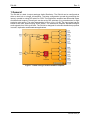
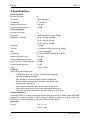
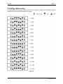
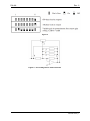
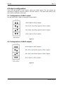
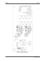
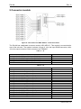
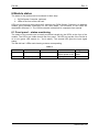
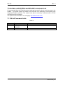
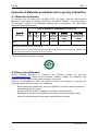
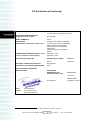
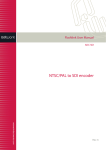
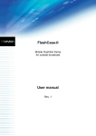
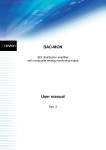
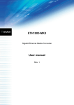
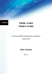
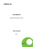
DA-AA Analog audio distribution amplifier User manual Rev. 6 Nevion Europe P.O. Box 1020, 3204 Sandefjord, Norway – Tel: +47 33 48 99 99 – Fax: +47 33 48 99 98 www.nevion.com DA-AA Rev. 6 Nevion Support Nevion Europe Nevion USA P.O. Box 1020 3204 Sandefjord, Norway Support phone 1: +47 33 48 99 97 Support phone 2: +47 90 60 99 99 1600 Emerson Avenue Oxnard, CA 93033, USA Toll free North America: (866) 515-0811 Outside North America: +1 (805) 247-8560 E-mail: [email protected] See http://www.nevion.com/support/ for service hours for customer support globally. Revision history Current revision of this document is the uppermost in the table below. Rev. Repl. Date 6 5 2011-03-02 5 4 3 2 1 0 A 4 3 2 1 0 A - 2008-01-31 2007-10-26 2007-10-05 2005-07-29 2004-11-10 2004-05-25 2003-10-21 Sign Change description AA/AJM New template. Updated Materials declaration and Declaration of Conformity. Changed max input, added IMD and frq. response. Added Declaration of Conformity. New front page and removed old logo. Added Materials Declaration and EFUP Corrected description of connector module. Changed page 8, output settings Exchanged ANA1 and ANA2 on dip setting Preliminary version nevion.com | 2 DA-AA Rev. 6 Contents Revision history .......................................................................................................... 2 1 General .................................................................................................................... 4 2 Specifications .......................................................................................................... 5 3 Configuration setup ................................................................................................. 6 4 Output configuration ................................................................................................ 8 4.1 Configuration of ANA1 output .......................................................................................... 8 4.2 Configuration of ANA2 outputs ........................................................................................ 8 5 Connector module ................................................................................................. 10 5.1 Mounting the connector module......................................................................................11 6 Module status ........................................................................................................ 12 6.1 Front panel – status monitoring ......................................................................................12 7 Interface with GYDA and RS-422 command set .................................................... 13 7.1 DA-AA Command table ..................................................................................................13 General environmental requirements for Nevion equipment..................................... 14 Product Warranty ...................................................................................................... 15 Appendix A Materials declaration and recycling information..................................... 16 A.1 Materials declaration ......................................................................................................16 A.2 Recycling information .....................................................................................................16 EC Declaration of Conformity ................................................................................... 17 nevion.com | 3 DA-AA Rev. 6 1 General The DA-AA is a dual 4 output analogue Audio Distributor. The DA-AA can be configured as either a dual 1x4 or a single 1x8 amplifier. The latter configuration is made by connecting the inputs in parallel or using DIP switch on PCB. The Distribution amplifier has differential inputs and differential outputs. Overall gain can be set by DIP switches or by potentiometer for high precision gain setting. The gain range setting is from -12 to +12 dB. The input signal can be mixed to the other channel using a DIP switch. The Distribution Amplifier handles analogue audio signals from 20Hz to 80 kHz. The DA-AA is designed for all audio distribution purposes in studio, duplication and Broadcast applications. Figure 1 - DA-AA analogue audio distribution amplifier nevion.com | 4 DA-AA Rev. 6 2 Specifications Electrical Input: Number of inputs: 2 Connector: DB15 balanced Impedance: > 10k ohms Maximum Input Level: +28 dBu Common mode rejection: >70dB Electrical Output: Number of outputs: 8 Connector: DB25 balanced (Tascam DA88) Frequency response: 50 Hz - 20 kHz ±0.05dB 20 Hz - 20 kHz ±0.1dB 20 Hz - 80 kHz ±0.2dB Crosstalk: -100 dB THD+N: > 100dB ref to 20 Hz-20 kHz @ 20dBu IMD: > 0.002%@18dBu Impedance: 40 ohms nominal. Maximum 55 ohms Maximum Output Level: +25 dBu Output voltage balance ratio: >30dB Output common mode rejection: >50dB Switched gain tolerance: 0.1dB Gain: -12 to +12 dB Features High quality audio distribution. Configurable dual 1x4 or single 1x8 distribution amplifier. Left/right swapping capability Gain setting for professional and consumer equipment. DIP switch gain compensation 10kohms / 600 ohms load Precision gain adjustment High common mode rejection on both inputs and outputs. Inputs and outputs may be used with unbalanced equipment. The input signal can be mixed to the other channel or vice versa. Control Interfaces Card edge LEDs for voltage monitoring, RS-422 with open protocol, SNMP Agent and WEB interface with GYDA controller. Control system for access to setup and module status with BITE (Built-In Test Equipment) for use with GYDA Control System Electrical Power: +5V / 0.1 W, ±15V / 1.9W nevion.com | 5 DA-AA Rev. 6 3 Configuration setup The DA-AA has two channels, ANA1 and ANA2. DIP switch 1 (ANA1) and 2 (ANA2) sets the individual channel properties according to table: Figure 2 nevion.com | 6 DA-AA Rev. 6 Figure 3 Figure 4 - Circuit diagram for advanced users nevion.com | 7 DA-AA Rev. 6 4 Output configuration There are two groups of four outputs, ANA1 and ANA2 output. The two groups are individually configured using DIP switch 3 and DIP switch 4. The switch sets which of the input that is connected to the output. 4.1 Configuration of ANA1 output Use dip switch SW4 / ANA1 for setting the outputs ANA1. Figure 5 4.2 Configuration of ANA2 outputs Figure 6 nevion.com | 8 DA-AA Rev. 6 Figure 7 - DA-AA board layout nevion.com | 9 DA-AA Rev. 6 5 Connector module Figure 8 - Overview of the ADC-AES-C1 connector module The DA-AA has a dedicated connector module: ADC-AES-C1. This module is mounted at the rear of the sub-rack. The module is shown in figure 6. J4 is the input DSUB connector, while J6 is the output connector. Both connectors are FEMALE. Table 1 – J4 Function Analogue Audio ANA1 positive input (ANA1+) Analogue Audio ANA1 negative input (ANA1-) Analogue Audio ANA2 positive input (ANA2+) Analogue Audio ANA2 negative input (ANA2-) Ground Pin 7 15 10 3 2, 5, 8, 11 Table 2 - J6 Function Analogue Audio ANA1 positive output 1 Analogue Audio ANA1 negative output 1 Analogue Audio ANA1 positive output 2 Analogue Audio ANA1 negative output 2 Analogue Audio ANA1 positive output 3 Analogue Audio ANA1 negative output 3 Analogue Audio ANA1 positive output 4 Analogue Audio ANA1 negative output 4 Analogue Audio ANA2 positive output 1 Analogue Audio ANA2 negative output 1 Analogue Audio ANA2 positive output 2 Analogue Audio ANA2 negative output 2 Analogue Audio ANA2 positive output 3 Analogue Audio ANA2 negative output 3 Analogue Audio ANA2 positive output 4 Analogue Audio ANA2 negative output 4 Ground Pin 24 12 10 23 21 9 7 20 18 6 4 17 15 3 1 14 2, 5, 8, 11,16,19, 22, 25 nevion.com | 10 DA-AA Rev. 6 5.1 Mounting the connector module. The details of how the connector module is mounted, is found in the user manual for the subrack frame FR-2RU-10-2. This manual is also available from our web site: http://www.nevion.com/ nevion.com | 11 DA-AA Rev. 6 6 Module status The status of the module can be monitored in three ways. 1. GYDA System Controller (optional). 2. LEDs at the front of the sub-rack. LEDs are mounted on the module itself, whereas the GYDA System Controller is a separate module giving detailed information on the card status. The functions of the LEDs are described in sections 5.1. The GYDA controller is described in a separate user manual 6.1 Front panel – status monitoring The status of the module can be easily monitored visually by the LED’s at the front of the module. The LED’s are visible through the front panel. The LED on top tells if the DA-AA is ok or not (green LED means ok – red is alarm). The second LED gives the input signal status. The DA-AA has 2 LEDs each showing a status corresponding. Table 3 Diode \ state Red LED Status Module is faulty Input No signal present Yellow LED Green LED No light Module is OK Module has no Module power is OK power Signal present nevion.com | 12 DA-AA Rev. 6 7 Interface with GYDA and RS-422 command set All commands follow the Flashlink protocol and can be used for direct control access to the module. The control system can either be a GYDA-SC or a third-party control system with integrated Flashlink protocol. The module can also be manually controlled with a VT100 compatible terminal program. The protocol can be found on our web page: http://www.nevion.com 7.1 DA-AA Command table Table 4 Command Response ? See protocol description Info Module status information Status Give module status Comment The “hello” command nevion.com | 13 DA-AA Rev. 6 General environmental requirements for Nevion equipment 1. 2. - The equipment will meet the guaranteed performance specification under the following environmental conditions: Operating room temperature range: 0°C to 40°C Operating relative humidity range: <90% (non-condensing) The equipment will operate without damage under the following environmental conditions: Temperature range: -10°C to 50°C Relative humidity range: <95% (non-condensing) nevion.com | 14 DA-AA Rev. 6 Product Warranty The warranty terms and conditions for the product(s) covered by this manual follow the General Sales Conditions by Nevion, which are available on the company web site: www.nevion.com nevion.com | 15 DA-AA Rev. 6 Appendix A Materials declaration and recycling information A.1 Materials declaration For product sold into China after 1st March 2007, we comply with the “Administrative Measure on the Control of Pollution by Electronic Information Products”. In the first stage of this legislation, content of six hazardous materials has to be declared. The table below shows the required information. Toxic or hazardous substances and elements 組成名稱 Part Name DA-AA 鉛 汞 镉 六价铬 多溴联苯 Lead Mercury Cadmium Hexavalent Polybrominated (Pb) (Hg) (Cd) Chromium biphenyls (Cr(VI)) (PBB) O O O O O 多溴二苯醚 Polybrominated diphenyl ethers (PBDE) O O: Indicates that this toxic or hazardous substance contained in all of the homogeneous materials for this part is below the limit requirement in SJ/T11363-2006. X: Indicates that this toxic or hazardous substance contained in at least one of the homogeneous materials used for this part is above the limit requirement in SJ/T11363-2006. This is indicated by the product marking: A.2 Recycling information Nevion provides assistance to customers and recyclers through our web site http://www.nevion.com/. Please contact Nevion’s Customer Support for assistance with recycling if this site does not show the information you require. Where it is not possible to return the product to Nevion or its agents for recycling, the following general information may be of assistance: Before attempting disassembly, ensure the product is completely disconnected from power and signal connections. All major parts are marked or labeled to show their material content. Depending on the date of manufacture, this product may contain lead in solder. Some circuit boards may contain battery-backed memory devices. nevion.com | 16 EC Declaration of Conformity MANUFACTURER Nevion Europe AS P.O. Box 1020, 3204 Sandefjord, Norway AUTHORIZED REPRESENTATIVE (Established within the EEA) Not applicable MODEL NUMBER(S) DA-AA DESCRIPTION Analogue Audio Distribution Amplifier DIRECTIVES this equipment complies with Low voltage (EU Directive 2006/95/EC) EMC (EU Directive 2004/108/EC) RoHS (EU Directive 2002/95/EC) 1 China RoHS WEEE (EU Directive 2002/96/EC) REACH HARMONISED STANDARDS applied in order to verify compliance with Directive(s) EN 55103-1:1996 EN 55103-2:1996 TEST REPORTS ISSUED BY Notified/Competent Body Report no: Nemko E07379.00 TECHNICAL CONSTRUCTION FILE NO Not applicable YEAR WHICH THE CE-MARK WAS AFFIXED 2008 TEST AUTHORIZED SIGNATORY MANUFACTURER AUTHORIZED REPRESENTATIVE (Established within EEA) Date of Issue 2008-07-24 Place of Issue Not applicable 1 Name Thomas Øhrbom Position VP of Quality, Nevion (authorized signature) Sandefjord, Norway Administration on the Control of Pollution Caused by Electronic Information Products Nevion Europe P.O. Box 1020, 3204 Sandefjord, Norway – Tel: +47 33 48 99 99 – Fax: +47 33 48 99 98 www.nevion.com