1
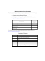
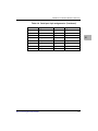
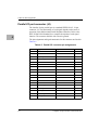
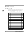
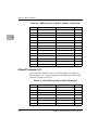
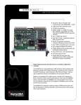
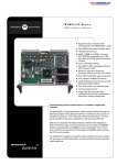
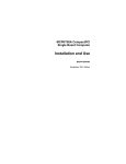
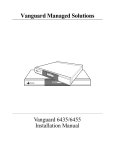
MVME761
Transition Module
Installation and Use
VME761A/IH4
November 19, 1999
Notice
While reasonable efforts have been made to assure the accuracy of this document,
Motorola, Inc. assumes no liability resulting from any omissions in this document, or from
the use of the information obtained therein. Motorola reserves the right to revise this
document and to make changes from time to time in the content hereof without obligation
of Motorola to notify any person of such revision or changes.
Electronic versions of this material may be read online, downloaded for personal use, or
referenced in another document as a URL to the Motorola Computer Group website. The
text itself may not be published commercially in print or electronic form, edited, translated,
or otherwise altered without the permission of Motorola, Inc.
It is possible that this publication may contain reference to or information about Motorola
products (machines and programs), programming, or services that are not available in your
country. Such references or information must not be construed to mean that Motorola
intends to announce such Motorola products, programming, or services in your country.
Restricted Rights Legend
If the documentation contained herein is supplied, directly or indirectly, to the U.S.
Government, the following notice shall apply unless otherwise agreed to in writing by
Motorola, Inc.
Use, duplication, or disclosure by the Government is subject to restrictions as set forth in
subparagraph (b)(3) of the Rights in Technical Data clause at DFARS 252.227-7013 (Nov.
1995) and of the Rights in Noncommercial Computer Software and Documentation clause
at DFARS 252.227-7014 (Jun. 1995).
Motorola, Inc.
Computer Group
2900 South Diablo Way
Tempe, Arizona 85282
Preface
MVME761 Transition Module Installation and Use provides general information, hardware
preparation, installation instructions and support information for the MVME761-001 and
MVME761-011 Transition Modules.
The MVME761-0x1 Transition Module is used as the interface between the following host
VMEmodules and various peripheral devices:
!
CAUTION
MVME2603-1121 to 1161
MVME2700-1421 to 1461
MVME2603-3121 to 3161
MVME2700-3221 to 3261
MVME2604-1321 to 1361
MVME2700-3321 to 3361
MVME2604-3321 to 3371
MVME2700-3421 to 3461
MVME2700-1221 to 1261
MVME3604-5342 to 5372
MVME2700-1321 to 1361
MVME4604-5342 to 5372
An MVME2600/MVME2700/MVME3600/MVME4600
module that is designed for use with an MVME712M
Transition Module will be damaged if you use it with an
MVME761-0x1 Transition Module.
This manual is intended for anyone who wants to design OEM systems, supply additional
capability to an existing compatible system, or for use in a lab environment for
experimental purposes.
A basic knowledge of computers and digital logic is assumed.
To use this manual you should be familiar with the publications listed in the following
section.
Motorola Computer Group Documents
The Motorola publications listed below are referenced in this manual. You can obtain paper
or electronic copies of Motorola Computer Group publications by:
❏
Contacting your local Motorola sales office
❏
Visiting Motorola Computer Group’s World Wide Web literature site,
http://www.mcg.mot.com/literature.
Document Title
Motorola
Publication
Number
MVME2600 Single Board Computer Installation and Use
V2600A/IH
MVME2700 Single Board Computer Installation and Use
V2700A/IH
MVME3600/4600 Series VME Processor Module
Installation and Use
V36V46A/IH
MVME3600/4600 Series VME Processor Module Programmer’s V36V46A/PG
Reference Guide
To obtain the most up-to-date product information in PDF or HTML format, visit
http://www.mcg.mot.com/literature.
Summary of Changes
Change Date
Description
11/19/99
Corrected transition module cable part numbers in Table 1-5. Updated
Motorola Computer Group Document listing.
5/14/99
Updated VME board model numbers in Preface and General Description
sections.
5/14/99
Added pinout information for P2 adapter cards. Table 4-8 and Table 4-11.
5/14/99
Updated Related Documentation table.
4/9/99
Corrected transition module cable part numbers in Table 1-5.
4/9/99
Added VME4600 board support
4/9/99
Updated all port 3 and 4 configuration drawings
Safety Summary
Safety Depends On You
The following general safety precautions must be observed during all phases of operation, service, and repair of this
equipment. Failure to comply with these precautions or with specific warnings elsewhere in this manual violates safety
standards of design, manufacture, and intended use of the equipment. Motorola, Inc. assumes no liability for the
customer’s failure to comply with these requirements.
The safety precautions listed below represent warnings of certain dangers of which Motorola is aware. You, as the user
of the product, should follow these warnings and all other safety precautions necessary for the safe operation of the
equipment in your operating environment.
Ground the Instrument.
To minimize shock hazard, the equipment chassis and enclosure must be connected to an electrical ground. The
equipment is supplied with a three-conductor ac power cable. The power cable must be plugged into an approved
three-contact electrical outlet. The power jack and mating plug of the power cable meet International Electrotechnical
Commission (IEC) safety standards.
Do Not Operate in an Explosive Atmosphere.
Do not operate the equipment in the presence of flammable gases or fumes. Operation of any electrical equipment in
such an environment constitutes a definite safety hazard.
Keep Away From Live Circuits.
Operating personnel must not remove equipment covers. Only Factory Authorized Service Personnel or other
qualified maintenance personnel may remove equipment covers for internal subassembly or component replacement
or any internal adjustment. Do not replace components with power cable connected. Under certain conditions,
dangerous voltages may exist even with the power cable removed. To avoid injuries, always disconnect power and
discharge circuits before touching them.
Do Not Service or Adjust Alone.
Do not attempt internal service or adjustment unless another person capable of rendering first aid and resuscitation is
present.
Use Caution When Exposing or Handling the CRT.
Breakage of the Cathode-Ray Tube (CRT) causes a high-velocity scattering of glass fragments (implosion). To prevent
CRT implosion, avoid rough handling or jarring of the equipment. Handling of the CRT should be done only by
qualified maintenance personnel using approved safety mask and gloves.
Do Not Substitute Parts or Modify Equipment.
Because of the danger of introducing additional hazards, do not install substitute parts or perform any unauthorized
modification of the equipment. Contact your local Motorola representative for service and repair to ensure that safety
features are maintained.
Dangerous Procedure Warnings.
Warnings, such as the example below, precede potentially dangerous procedures throughout this manual. Instructions
contained in the warnings must be followed. You should also employ all other safety precautions which you deem
necessary for the operation of the equipment in your operating environment.
!
WARNING
Dangerous voltages, capable of causing death, are present in this equipment.
Use extreme caution when handling, testing, and adjusting.
!
WARNING
This equipment generates, uses, and can radiate electromagnetic energy. It may cause or be susceptible to electromagnetic interference (EMI) if not installed and used in a
cabinet with adequate EMI protection.
European Notice: Board products with the CE marking comply with the EMC
Directive (89/336/EEC). Compliance with this directive implies conformity to the
following European Norms:
EN55022 (CISPR 22) Radio Frequency Interference
EN50082-1 (IEC801-2, IEC801-3, IEEC801-4) Electromagnetic Immunity
The product also fulfills EN60950 (product safety) which is essentially the
requirement for the Low Voltage Directive (73/23/EEC).
This board product was tested in a representative system to show compliance with
the above mentioned requirements. A proper installation in a CE-marked system
will maintain the required EMC/safety performance.
Motorola® and the Motorola symbol are registered trademarks of Motorola, Inc.
All other products mentioned in this document are trademarks or registered trademarks of
their respective holders.
© Copyright Motorola 1998, 1999
All Rights Reserved
Printed in the United States of America
Contents
CHAPTER 1
General Information
Introduction................................................................................................................1-1
Product Overview.......................................................................................................1-1
Features ......................................................................................................................1-1
General Description ...................................................................................................1-2
Serial Port Interface Modules ....................................................................................1-4
P2 Adapter Boards .....................................................................................................1-5
Three-row P2 adapter (MVME761-001) ............................................................1-5
Five-Row P2 adapter (MVME761-011) .............................................................1-6
Connectors and Cables...............................................................................................1-7
Specifications .............................................................................................................1-9
Cooling requirements..........................................................................................1-9
FCC compliance .................................................................................................1-9
CHAPTER 2
Hardware Preparation and Installation
Introduction................................................................................................................2-1
Unpacking the Hardware ...........................................................................................2-1
Installing the Serial Interface Modules ......................................................................2-2
Installing the Transition Module and P2 Adapter ......................................................2-5
Procedure ............................................................................................................2-6
CHAPTER 3
Functional Description
Introduction................................................................................................................3-1
Circuitry .....................................................................................................................3-1
P2 Signal Multiplexing (P2MX) ................................................................................3-4
Serial Interface Module Circuitry ..............................................................................3-7
Port Configuration Diagrams .....................................................................................3-8
COM1 and COM2 asynchronous serial ports.....................................................3-8
Asynchronous/Synchronous Serial Ports..........................................................3-10
vii
CHAPTER 4
Connector Pin Assignments
Introduction ............................................................................................................... 4-1
MVME761 Transition Module Connectors............................................................... 4-1
P2 connector ....................................................................................................... 4-1
Asynchronous serial port connectors (J5/J6)...................................................... 4-3
Asynchronous/Synchronous serial port connectors (J7/J8)................................ 4-4
Parallel I/O port connector (J4) .......................................................................... 4-6
Ethernet Connector (J9)...................................................................................... 4-7
P2 Adapter Connectors.............................................................................................. 4-8
3-Row P2 adapter (J2) ........................................................................................ 4-8
3-Row P2 adapter (J3) ........................................................................................ 4-9
5-Row P2 adapter (J1) ...................................................................................... 4-10
PMC I/O, 5-Row P2 adapter (J3) ..................................................................... 4-12
5-Row P2 adapter (J4) ...................................................................................... 4-13
viii
List of Figures
Figure 1-1. MVME761 transition module front panel and component side..............1-3
Figure 1-2. 3-row DIN backplane P2 adapter (MVME761-001)...............................1-5
Figure 1-3. 5-row DIN backplane P2 adapter (MVME761-011)...............................1-6
Figure 2-1. Serial port interface jumper settings........................................................2-2
Figure 2-2. Serial interface module and connector P1...............................................2-3
Figure 2-3. Installing a SIM onto the MVME761 transition module ........................2-4
Figure 2-4. MVME761-0x1 chassis connections.......................................................2-6
Figure 3-1. MVME761 transition module block diagram .........................................3-2
Figure 3-2. 3-Row DIN backplane P2 adapter block diagram...................................3-3
Figure 3-3. 5-Row DIN backplane P2 adapter block diagram...................................3-3
Figure 3-4. Multiplex signal timing chart ..................................................................3-6
Figure 3-5. EIA-574 DTE port configuration (COM1 and COM2) ..........................3-9
Figure 3-6. MVME761 EIA232 DCE configuration port 3.....................................3-11
Figure 3-7. MVME761 EIA232 DCE configuration port 4.....................................3-12
Figure 3-8. MVME761 EIA232-DTE configuration port 3.....................................3-13
Figure 3-9. MVME761 EIA232-DTE configuration port 4.....................................3-14
Figure 3-10. MVME761 EIA530-DCE configuration port 3 ..................................3-15
Figure 3-11. MVME761 EIA530-DCE configuration port 4 ..................................3-16
Figure 3-12. MVME761 EIA530-DTE configuration port 3...................................3-17
Figure 3-13. MVME761 EIA530-DTE configuration port 4...................................3-18
Figure 3-14. MVME761 V.35 DCE configuration port 3 ........................................3-19
Figure 3-15. MVME761 V.35 DCE configuration port 4 ........................................3-20
Figure 3-16. MVME761 V.35 DTE configuration port 3 ........................................3-21
Figure 3-17. MVME761 V.35 DTE configuration port 4 ........................................3-22
Figure 3-18. MVME761 X.21-DCE configuration port 3 .......................................3-23
Figure 3-19. VME761 X.21-DCE configuration port 4...........................................3-24
Figure 3-20. VME761 X.21-DTE configuration port 3 ...........................................3-25
Figure 3-21. VME761 X.21-DTE configuration port 4 ...........................................3-26
ix
List of Tables
Table 1-1. SIM part numbers .....................................................................................1-4
Table 1-2. MVME761 transition module connectors.................................................1-7
Table 1-3. 3-Row P2 adapter connectors (MVME761-001) ......................................1-7
Table 1-4. 5-Row P2 adapter connectors (MVME761-011) ......................................1-8
Table 1-5. MVME761 transition module cables ........................................................1-8
Table 1-6. MVME761-0x1 specifications ..................................................................1-9
Table 3-1. P2 signal multiplexing sequence...............................................................3-4
Table 4-1. MVME761 P2 connector pin assignments ...............................................4-1
Table 4-2. COM1 and COM2 pin assignments..........................................................4-3
Table 4-3. Serial port 3 pin assignments ....................................................................4-4
Table 4-4. Serial port 4 pin assignments ....................................................................4-4
Table 4-5. Parallel I/O connector pin assignments.....................................................4-6
Table 4-6. 10Base-T/100Base-TX pin assignments...................................................4-7
Table 4-7. 8-bit SCSI connector (3-Row P2 adapter) ................................................4-8
Table 4-8. VME connector (3-Row P2 adapter) ........................................................4-9
Table 4-9. 16-bit SCSI connector (5-Row P2 adapter) ............................................4-10
Table 4-10. PMC I/O connector (5-Row P2 adapter) ..............................................4-12
Table 4-11. VME connector (3-Row P2 adapter) ....................................................4-13
x
1General Information
1
Introduction
This manual provides general information, hardware preparation,
installation instructions, and a functional description for the
MVME761-001 and MVME761-011 Transition Modules.
Product Overview
The MVME761-0x1 Transition Module provides the interface between the
MVME260x, MVME270x, MVME360x, or MVME460x Single Board
Computer VMEmodule and various peripheral devices. This module
provides industry standard connectors to simplify customer cable
requirements for the serial port, printer, and Ethernet signals.
Features
The features of the MVME761-0x1 Transition Module include:
❏
Industry-standard connectors for these interfaces:
– Two EIA-574 asynchronous serial ports (DTE)
– Two asynchronous/synchronous serial ports, which can be
configured for EIA-232-D, EIA-530, V.35, or X.21 interfaces
(DCE or DTE)
– One parallel port (IEEE Standard 1284-I compliant)
– 10Base-T/100Base-TX Ethernet
❏
Two 60-pin Serial Interface Module (SIM) connectors for
configuring the asynchronous/synchronous serial ports
❏
Single-width board
❏
Electro-Magnetic Interference (EMI) and Electro-Static Discharge
(ESD) protection
1-1
1
General Information
General Description
TheMVME761-0x1 Transition Module provides the interface between the
standard Ethernet, parallel port, and the serial port connectors, and the
following MVME260x, MVME270x, MVME360x, and MVME460x
Single Board Computer VME modules:
MVME2603-1121 to 1161
MVME2700-1421 to 1461
MVME2603-3121 to 3161
MVME2700-3221 to 3261
MVME2604-1321 to 1361
MVME2700-3321 to 3361
MVME2604-3321 to 3371
MVME2700-3421 to 3461
MVME2700-1221 to 1261
MVME3604-5342 to 5372
MVME2700-1321 to 1361
MVME4604-5342 to 5372
All port I/O controllers reside on the MVME260x, MVME270x,
MVME360x, and MVME460x Single Board Computer modules. The
MVME761 transition module Ethernet and parallel port circuitry is
passive. The serial port circuitry provides multiplexing and buffering
functions (refer to P2 Signal Multiplexing (P2MX) on page 3-4). The
multiplexing function is transparent to the user.
Both MVME761-0x1 models use the same transition module. The
MVME761-001 comes with a P2 adapter that connects to a 3-row DIN
chassis backplane. The MVME761-011 comes with a P2 adapter that
connects to a 5-row DIN chassis backplane.
Figure 1-1 shows the MVME761 transition module component layout and
the front panel. See Table 1-2 for a list of the front panel port connectors.
1-2
Computer Group Literature Center Web Site
General Description
MVME
761-001
COM1
J5
COM2
J6 DTE
1
DCE
J2
3
SERIAL 3
60
J1
59
2
1
J7
SERIAL 4
60
J12
59
2
1
J8
DTE
DCE
J3
1
3
PARALLEL
J4
P2
10/100 BASET
J9
1910 9609
Figure 1-1. MVME761 transition module front panel and component side
http://www.mcg.mot.com/literature
1-3
1
1
General Information
Serial Port Interface Modules
You may configure the asynchronous/synchronous serial ports (ports 3 and
4) to the appropriate interface by installing a Serial Interface Module
(SIM). A SIM is a small “plug-in” printed circuit board that converts the
TTL-level synchronous or asynchronous port signals to industry standard
voltage levels used by the ports. The SIM contains the receiver and
transmitter circuits for converting the input and output signals of the host
VMEmodule to the appropriate serial data communication protocol.
The SIMs for the MVME761-0x1 are listed in the following table.
Table 1-1. SIM part numbers
Interface
Model Number
Part Number
EIA-232-D DCE
SIM232DCE
01-W3876B01B
EIA-232-D DTE
SIM232DTE
01-W3877B01A
EIA-530 DCE
SIM530DCE
01-W3878B01B
EIA-530 DTE
SIM530DTE
01-W3879B01B
V.35 DCE
SIMV35DCE
01-W3128F01A
V.35 DTE
SIMV35DTE
01-W3127F01A
X.21 DCE
SIMX21DCE
01-W3167F01B
X.21 DTE
SIMX21DTE
01-W3166F01A
Note
1-4
Additional SIMs may be released. Please see your Motorola
representative for a complete list of SIMS that are available
for the MVME761-0x1.
Computer Group Literature Center Web Site
P2 Adapter Boards
P2 Adapter Boards
The P2 adapters route the asynchronous and synchronous port, printer port,
and Ethernet signals to the MVME761 transition module.
Three-row P2 adapter (MVME761-001)
The P2 adapter for the MVME761-001 mounts onto a 3-row, 96-pin P2
backplane connector. The 50-pin male connector, J2, carries the
8-bit SCSI signals from the MVME260x, MVME270x, MVME360x, or
MVME460x. To run SCSI devices, you may install an additional transition
module that is equipped with a SCSI port, such as the MVME712B.
50
49
J2 2
1
J3
2
1
64
63
C1
1
J1
25
R1
9
C5
C6
C4
+
17
C3
C7
R2
U1
C 1
B
A
C2
CR1
U2
+
32 C
B
A
P1
1933 9610
Figure 1-2. 3-row DIN backplane P2 adapter (MVME761-001)
This P2 adapter, and the cable for connecting to the MVME761 transition
module, can be ordered separately as model MVME761P2-001.
http://www.mcg.mot.com/literature
1-5
1
1
General Information
Five-Row P2 adapter (MVME761-011)
The P2 adapter for the MVME761-011 mounts onto a 5-row, 160-pin P2
backplane connector. The 68- pin female connector, J1, carries
16-bit SCSI signals from the MVME260x, MVME270x, MVME360x, or
MVME460x. It also has a 64-pin male connector, J3, for PMC I/O.
J1
1
J3
33
2
1
64
63
2
1
64
63
J5
J4
1
25
1
U1
9
C8
+
U2
17
U3
25
C9
9
R4
17
+
1
D
C
B
A
Z
CR1
32
D
C
B
A
Z
P1
1999 9701
Figure 1-3. 5-row DIN backplane P2 adapter (MVME761-011)
This P2 adapter, and the cable for connecting to the MVME761 transition
module, can be ordered separately as model MVME761P2-011.
1-6
Computer Group Literature Center Web Site
Connectors and Cables
Connectors and Cables
The connectors on the MVME761 transition module and the P2 adapters
are listed in the following tables. The port connectors are located on the
front panel, which is shown in Figure 1-1. See Table 1-5 on page 1-8 for a
list of the cables. See Chapter 4 for the connector pin assignments.
The cable used for connecting the MVME761 transition module to the P2
adapter is provided with the MVME761-0x1. You will need to purchase or
fabricate the port cables.
Table 1-2. MVME761 transition module connectors
Type
Number
Description
COM1 and
COM2
J5
J6
9-pin male DIN asynchronous serial port
connector
Serial port 3
Serial port 4
J7
J8
26-pin female HD-26 synchronous serial port
connector
Parallel port
J4
36-pin female parallel port connector
10Base-T,
100Base-TX
J9
8-pin female RJ-45 Ethernet port connector
SIM
J1, J12
60-pin female connector
VME
P2
64-pin male connector to J2 on the P2 adapter
Table 1-3. 3-Row P2 adapter connectors (MVME761-001)
Type
Number
Description
VME
P1
96-pin female DIN 41612 connector to the chassis
backplane
J3
64-pin male connector for output to P2 on the MVME761
transition module
J2
50-pin male IDC connector for internal SCSI devices
SCSI
http://www.mcg.mot.com/literature
1-7
1
1
General Information
Table 1-4. 5-Row P2 adapter connectors (MVME761-011)
Type
Number
Description
VME
P1
160-pin female DIN 41612 connector to the chassis
backplane
J4
64-pin male connector for output to P2 on the
MVME761 transition module
PMC I/O
J3
64-pin male connector for PMC I/O
SCSI
J1
68-pin female IDC connector for internal SCSI devices
Table 1-5. MVME761 transition module cables
Part Number
Description
Included with the
MVME761-0x1
64-line flat ribbon cable with 96-pin DIN connectors that
connects P2 on the MVME761 transition module to J3
on the 3-row P2 Adapter or J4 on the 5-row P2 adapter;
13 inches long. (30-W2799B02A).
User-supplied
EIA-232-D DTE or DCE cable (pins used depend on the
processor VMEmodule)
User-supplied
Centronics- type parallel printer cable, male-to-male
User-supplied
20-conductor cable; usually supplied with the modem
User-supplied
6-conductor cable; usually supplied with the modem
CBL761HD26DB25
Straight-through adapter cable with male HD-26
connector and female DB-25 connector, 3 feet long.
(30-NW9302B27)
Note
1-8
If you supply your own 64-line cable to connect the P2 adapter to
the MVME761 transition module, the cable should not be longer
than 1.5 feet. A longer cable is likely to cause problems, especially
for the Ethernet and parallel port signals.
Computer Group Literature Center Web Site
Specifications
Specifications
The MVME761 transition module specifications are shown in Table 1-6.
Table 1-6. MVME761-0x1 specifications
Characteristics
Specifications
Power Requirements
+12Vdc, 100mA typical, 200mA maximum
-12Vdc, 100mA (for some of the SIMs)
Operating temperature
0o to 55o C at chassis point of entry of forced air
(approximately 5 CFM)
Storage temperature
-40o to +85o C
Relative Humidity
5% to 90% (non-condensing)
Board Size
(excluding front panel)
Height: 9.187 inches(233.35 mm)
Height: 3.200 inches(80.00 mm)
Thickness: 0.063 inches (1.60 mm)
Cooling requirements
The MVME761-0x1 is tested to operate under forced air cooling with an
incoming air temperature range of 0 degrees C to 55 degrees C. Adequate
cooling can be achieved with air flowing over the module at 5 cubic feet
per minute. The exact amount of airflow required for cooling depends on
the ambient air temperature and the type, number, and location of modules
and other heat sources.
FCC compliance
The MVME761-0x1 was tested in an FCC-compliant chassis, and meets
the requirements for Class A equipment. For minimum RF emissions, it is
essential that you implement the following conditions:
❏
Install shielded cables on all external I/O ports
❏
Connect conductive chassis rails to earth ground to provide a path
for connecting shields to earth ground
❏
Tighten all front panel screws
http://www.mcg.mot.com/literature
1-9
1
2Hardware Preparation and
Installation
2
Introduction
This chapter provides unpacking instructions, hardware preparation, and
installation instructions for the MVME761 transition module, the P2
adapter, and the Serial Interface Modules.
Unpacking the Hardware
Use ESD
Wrist Strap
The MVME761-0x1 is packed in an antistatic wrapper to protect it from
static discharge. Motorola strongly recommends that you use an antistatic
wrist strap and a conductive foam pad when handling the equipment.
Electronic components can be extremely sensitive to electrostatic
discharge (ESD). After removing the board from the protective wrapper,
place it component side up on a grounded, static-free surface. Do not slide
the board over any surface.
Unpack the equipment from the shipping carton. Refer to the packing list
and verify that all items are present. Save the packing material for storing
and reshipping of the equipment.
2-1
Hardware Preparation and Installation
2
Installing the Serial Interface Modules
Configure the serial ports 3 and 4 for the required interface by installing
the appropriate SIM. See Table 1-1 on page 1-4 for a list of the serial port
interface types.
Prior to installing the SIMs, set the jumpers on header J2 (for serial port 3)
and header J3 (for serial port 4) for either DCE or DTE. Set the jumper to
position:
❏
1-2 if the SIM is for a DTE interface
❏
2-3 if the SIM is for a DCE
1
2
DTE
3
1
2
3
DCE
11650 9610
Figure 2-1. Serial port interface jumper settings
Note
You must set the jumpers and install the SIMs prior to
installing the MVME761 transition module in the system
chassis.
The SIMs plug into connector J1 (for serial port 3) or J12 (for serial port
4) on the MVME761 transition module.
Install the SIMs on the MVME761 transition module per the following
procedure:
1. Align the SIM so that P1 on the SIM lines up with the appropriate
SIM connector (J1 for serial port 3 or J12 for serial port 4) on the
transition module. Note the position of the alignment key on P1. See
Figure 2-2.
2-2
Computer Group Literature Center Web Site
Installing the Serial Interface Modules
2
Mounting Hole
P1
Alignment
Key
Mounting Hole
11637 9610
Figure 2-2. Serial interface module and connector P1
2. Place the SIM onto the transition module SIM connector, making
sure that the mounting holes also line up with the standoffs on the
transition module as shown in Figure 2-3.
3. Gently press the top of the SIM to seat it on the transition module
SIM connector. If the SIM does not seat with gentle pressure, recheck the alignment of the connectors.
Note
Do not force the SIM onto the transition module.
4. Secure the SIM to the transition module standoffs with the two
Phillips-head screws provided. Do not over tighten the screws.
http://www.mcg.mot.com/literature
2-3
Hardware Preparation and Installation
2
1911 9609
Figure 2-3. Installing a SIM onto the MVME761 transition module
2-4
Computer Group Literature Center Web Site
Installing the Transition Module and P2 Adapter
Installing the Transition Module and P2 Adapter
Install the MVME761 transition module and P2 adapter in the system
chassis. The P2 adapter is required because the P2 connector on the
transition module is not compatible with the P2 connector on the chassis
backplane.
Use ESD
Wrist Strap
Motorola strongly recommends that you use an antistatic wrist strap and a
conductive foam pad when installing boards in a system chassis.
Electronic components, such as disk drives, computer boards, and memory
modules, can be extremely sensitive to ESD. Place the board flat on a
grounded, static-free surface, component-side up. Do not slide the board
over any surface.
If an ESD station is not available, you can avoid damage resulting from
ESD by attaching the ESD wrist strap to an unpainted metal part of the
system chassis.
Install the MVME761-0x1 in the system chassis per the Procedure on page
2-6. Refer to Figure 2-4, which shows the cabling and connections within
the chassis.
!
Caution
!
An MVME2600/MVME2700/MVME3600/MVME4600
module that is designed for use with an MVME712M
Transition Module will be damaged if you use it with an
MVME761-0x1 Transition Module.
Connecting modules while power is applied may result in
damage to components on the module.
Caution
!
Warning
Dangerous voltages, capable of causing death, are present in
this equipment. use extreme caution when handling, testing,
and adjusting.
http://www.mcg.mot.com/literature
2-5
2
Hardware Preparation and Installation
2
VME BACKPLANE
MVME260x/MVME360x
MVME761 Transition Module
P1
30-W2799B02A
64-CONDUCTOR
CABLE
P2 ADAPTER
P2
P1
P2
J3 ON THE 3-ROW P2 ADAPTER
J4 ON THE 5-ROW P2 ADAPTER
ENCLOSURE BOUNDARY
11654.00 9610
Figure 2-4. MVME761-0x1 chassis connections
Procedure
1. Turn all equipment power OFF and disconnect the power cable
from the AC power source.
2. Remove the chassis cover per the instructions in the equipment
user’s manual.
3. If the chassis has a rear card cage, remove the filler panel(s) from
the appropriate card slot(s) at the rear of the chassis.
2-6
Computer Group Literature Center Web Site
Installing the Transition Module and P2 Adapter
4. If necessary, move some of the other modules to allow space for the
cables connected to the P2 adapter and the transition module.
5. Install the jumper on header J1 (on the 3-row P2 adapter or header
J5 on the 5-row P2 adapter) if you are supporting SCSI devices.
6. Attach the P2 adapter, for either the 3-row or 5-row version, to the
backplane connector that is directly in line with the P2 connector on
the MVME260x, MVME270x, MVME360x, or MVME460x.
Note
Be sure to orient pin 1 of the P2 adapter’s connector with pin
1 of the backplane connector.
7. Attach the 64-conductor cable (furnished with the MVME761-0x1)
to the P2 adapter (J3 on the 3-row version, J4 on the 5-row version).
Be sure to orient cable pin 1 with connector pin 1.
8. Attach the 64-conductor cable to connector P2 on the transition
module. Be sure to orient cable pin 1 with connector pin 1.
9. Insert the transition module into the chassis slot, and tighten the
attaching screws.
Note
Make sure there is good contact with the transverse mounting
rails in order to minimize RF emissions.
10. Install the chassis cover, making sure that cables are not pinched by
the cover.
11. Connect the power cable to the AC power source.
http://www.mcg.mot.com/literature
2-7
2
3Functional Description
3
Introduction
This chapter provides information on MVME761 transition module and
SIM circuitry, P2 signal multiplexing, and the configuration of the serial
ports.
Circuitry
The MVME761 transition module and the Serial Interface Modules
(SIMs) convert the TTL level signals to and from the MVME260x,
MVME270x, MVME360x, and MVME460x modules to the reception and
transmission levels specified by the appropriate port interface standard.
The MVME761 transition module contains a small amount of “house
keeping” circuitry. Bulk capacitors are on the power sources (+5Vdc,
+12Vdc, and -12Vdc). Pullup resistors put the inputs to the MVME260x,
MVME270x, MVME360x, and MVME460x in a known high even when
no SIM is installed.
The block diagram for the MVME761 transition module is shown in
Figure 3-1. The block diagram for the 3-row DIN backplane P2 adapter is
shown in Figure 3-2. The block diagram for the 5-row DIN backplane P2
adapter is shown in Figure 3-3.
3-1
Functional Description
3
10Base-T
100Base-TX
Parallel
COM1
COM2
Serial 3
Serial 4
Serial Interface
Module (SIM)
Serial Interface
Module (SIM)
Buffers
EIA-232-D
P2 Multiplex Function
64-Pin DIN Connector
11638.00 9611
Figure 3-1. MVME761 transition module block diagram
3-2
Computer Group Literature Center Web Site
Circuitry
8-bit Single-ended SCSI
64-pin Connector to MVME761 Transition Module
3
SCSI
Terminators
3-Row Backplane Connector
11639.00 9611
Figure 3-2. 3-Row DIN backplane P2 adapter block diagram
16-bit Single-ended SCSI
64-pin Connector to MVME761 Transition Module
SCSI
Terminators
PMC I/O
5-Row Backplane Connector
11752.00 9703
Figure 3-3. 5-Row DIN backplane P2 adapter block diagram
http://www.mcg.mot.com/literature
3-3
Functional Description
P2 Signal Multiplexing (P2MX)
Because of a limited number of pins on the P2 connector, both the VME
processor board and the MVME761 transition module multiplex and demultiplex some of the P2 signals. This function, called P2MX is
transparent to the software and the user.
3
Four pins are used for the signal multiplexing:
❏
MXCLK
❏
MXSYNC#
❏
MXDO
❏
MXDI
Sixteen time slots are defined and allocated. The signal multiplexing
sequences are listed in Table 3-1.
Table 3-1. P2 signal multiplexing sequence
3-4
MXDO
(from the
MVME260x/MVME270x/MVME360x/
MVME460x)
MXDI
(from the MVME761)
Time Slot
Time Slot
Signal Name
Signal Name
0
RTS3
0
CTS3
1
DTR3
1
DSR3/MID1
2
LLB3/MODSEL
2
DCD3
3
RLB3
3
TM3/MID0
4
RTS4
4
RI3
5
DTR4
5
CTS4
6
LLB4
6
DSR4/MID3
7
RLB4
7
DCD4
8
IDREQ#
8
TM4/MID2
9
DTR1
9
RI4
10
DTR2
10
RI1
Computer Group Literature Center Web Site
P2 Signal Multiplexing (P2MX)
Table 3-1. P2 signal multiplexing sequence
MXDO
(from the
MVME260x/MVME270x/MVME360x/
MVME460x)
MXDI
(from the MVME761)
Time Slot
Time Slot
Signal Name
3
Signal Name
11
Reserved
11
DSR1
12
Reserved
12
DCD1
13
Reserved
13
RI2
14
Reserved
14
DSR2
15
Reserved
15
DCD2
MXCLK is the 10MHz bit clock for the time-multiplexed data lines,
MXDO and MXDI.
MXSYNC# is asserted for one bit time at Time Slot 15 by the
MVME260x, MVME270x, MVME360x, or MVME460x. MXSYNC# is
used by the MVME761 transition module to synchronize with the VME
modules.
MXDO is the time-multiplexed output line from the main board and
MXDI is the time-multiplexed line from the MVME761 transition module.
A 16-to-1 multiplexing scheme is used with a 10MHz bit rate.
MXSYNC# is clocked out using the falling edge of MXCLK and MDXO
is clocked out with the rising edge of the MXCLK. MXDI is sampled at
the rising edge of MXCLK (the transition module synchronizes MXDI
with MXCLK’s rising edge).
The timing relationships among MXCLK, MXSYNC#, MXDO, and
MXDI are illustrated in Figure 3-4.
http://www.mcg.mot.com/literature
3-5
Functional Description
3
Time Slot 15
Time Slot 0
Time Slot 1
Time Slot 2
Time Slot 3
MXDO
Reserved
RTS3
DTR3
LLB3
RLB3
MXDI
DCD2
CTS3
DSR3
DCD3
TM3
MXCLK
MXSYNC#
11640.00 9611
Figure 3-4. Multiplex signal timing chart
3-6
Computer Group Literature Center Web Site
Serial Interface Module Circuitry
Serial Interface Module Circuitry
Each Serial Interface Module has a 60-pin connector that provides all
signal and power connections to the MVME761 transition module.
3
TTL-level signals
All TTL-level signals, with the exception of data and clocks, are active
low. The pullup resistors on the MVME761 transition module drive all
TTL inputs to the SIM to a known logic level.
SIMs
The SIMs have surge suppression circuitry for all port signals going to the
external connector. This consists of a series resistor and a dual 15V clamp
diode to chassis ground. All series resistors are 100 ohms except on the
EIA-530 balanced drives, which use 10 ohm series resistors.
❏
EIA-232-D SIMs employ MC145406 ICs as line transmitters to
convert the TTL output signals from the MVME260x, MVME270x,
MVME360x, or MVME460x module to EIA-232-D voltage levels.
As line receivers, the MC145406 ICs convert the EIA-232-D input
signals to TTL voltage levels which are sent to the VME module.
The MC145406 transceiver IC requires a series diode on the +12V
supply and a clamp diode to logic ground on the -12V supply. The
diodes are located on the transition module rather than on the SIM
due to space limitations.
❏
EIA-530 and X.21 SIMs employ AM26C31CD ICs as transmitters
to convert the TTL output signals from the MVME260x,
MVME270x, MVME360x, or MVME460x module to balanced
signals. As line receivers, the AM26C32CD ICs convert the
balanced input signals to TTL signals which are sent to the VME
module.
❏
V.35 SIMs employ LTC1345T ICs as transmitters to convert the
TTL output signals from the MVME260x, MVME270x,
MVME360x, or MVME460x module to balanced signals. As line
receivers, the LTC1345R ICs convert the balanced input signals to
TTL signals which are sent to the VME module.
http://www.mcg.mot.com/literature
3-7
Functional Description
For all port interfaces, the SIMs support the transmitter signal element
timing as either input or output signals.
3
Port Configuration Diagrams
COM1 and COM2 asynchronous serial ports
The asynchronous serial port (COM1 and COM2) configuration is shown
in Figure 3-5.
3-8
Computer Group Literature Center Web Site
Port Configuration Diagrams
DB9
TXD
SOUT1
3
3
RTS
RTS1#
7
DTR
DTR1#
4
RXD
SIN1
2
COM1
CTS
CTS1#
8
DSR
6
DSR1#
DCD
DCD1#
RI
RI1#
1
9
GND
5
PC87308
P2/P2MX
DB9
TXD
SOUT2
3
RTS
RTS2#
7
DTR
DTR2#
4
RXD
SIN2
2
CTS
CTS2#
COM2
8
DSR
DSR2#
6
DCD
DCD2#
1
RI
RI2#
9
GND
5
MVME260X/
MVME360X
MVME761
Transition Module
Figure 3-5. EIA-574 DTE port configuration (COM1 and COM2)
http://www.mcg.mot.com/literature
3-9
Functional Description
Asynchronous/Synchronous Serial Ports
The asynchronous/synchronous serial port (Port 3 and Port 4) interface
configuration diagrams are on the following pages.
3
3-10
Computer Group Literature Center Web Site
Port Configuration Diagrams
3
MVME761
VME MODULE
Z85230 SCC
HD26
EIA232-DCE SIM
TXD
3
RTS#
5
RXD
2
CTS#
4
DCD#
20
J18
TRXC
J2
3
2
3
2
1
1
15
17
24
RTXC
P2/P2MX
DCE
Z8536 CIO
DTR#
8
LLB#
25
RLB#
22
DSR#
6
RI#
21
TM#
18
7
Header J18 1-2
Header J2 2-3
11552 9902 (2-5)
Figure 3-6. MVME761 EIA232 DCE configuration port 3
http://www.mcg.mot.com/literature
3-11
Functional Description
3
VME MODULE
MVME761
Z85230 SCC
HD26
EIA232-DCE SIM
TXD
3
RTS#
5
RXD
2
CTS#
4
DCD#
20
J17
J19
J3
1
2
3
2
3
1
15
17
J16
TRXC
1
2
RTXC
3
24
P2/P2MX
DCE
Z8536 CIO
DTR#
8
LLB#
25
RLB#
22
DSR#
6
RI#
21
TM#
18
7
Headers: J16 2-3
J17 1-2
J19 1-2
Header J3 2-3
11552 9902 (3-5)
Figure 3-7. MVME761 EIA232 DCE configuration port 4
3-12
Computer Group Literature Center Web Site
Port Configuration Diagrams
VME MODULE
3
MVME761
Z85230 SCC
HD26
EIA232-DTE SIM
TXD
2
RTS#
4
RXD
3
CTS#
5
DCD#
8
J18
TRXC
J2
3
2
3
1
1
24
2
15
17
RTXC
P2/P2MX
DTE
Z8536 CIO
DTR#
20
LLB#
18
RLB#
21
DSR#
6
RI#
22
TM#
25
7
Header J18 2-3
Header J2 1-2
11552 9902(4-5)
Figure 3-8. MVME761 EIA232-DTE configuration port 3
http://www.mcg.mot.com/literature
3-13
Functional Description
3
MVME761
VME MODULE
Z85230 SCC
HD26
EIA232-DTE SIM
TXD
2
RTS#
4
RXD
3
CTS#
5
DCD#
8
J17
J19
J3
1
2
3
3
1
24
2
15
J16
TRXC
1
2
RTXC
3
17
P2/P2MX
DTE
Z8536 CIO
DTR#
20
LLB#
18
RLB#
21
DSR#
6
RI#
22
TM#
25
7
Headers: J16 2-3
J17 2-3
J19 1-2
Header J3 1-2
11552 9902 (5-5)
Figure 3-9. MVME761 EIA232-DTE configuration port 4
3-14
Computer Group Literature Center Web Site
Port Configuration Diagrams
MVME761
VME MODULE
EIA530-DCE SIM
Z85230 SCC
DB26
RXDB
RXDA
TXD
CTSB
RTS#
CTSA
3
16
3
13
5
TXDB
RXD
+
-
CTS#
+
-
DCD#
+
-
14
2
TXDA
RTSB
19
4
RTSA
DTRB
DTRA
J18
TRXC
TXCB
3
3
2
2
1
1
P2/P2MX
TXCA
RXCB
RXCA
J2
ETXCB
+
-
RTXC
ETXCA
23
20
12
15
9
17
11
24
DCE
Z8536 CIO
DCDB
DTR#
DCDA
TM
LLB#
26
DSRB
DSR#
DSRA
RI#
+
-
TM#
+
-
-V
8
25
RI
RLB#
10
22
6
RL
21
-V
LL
18
GND
7
Header J18 1-2
Header J2 2-3
2191 9902
Figure 3-10. MVME761 EIA530-DCE configuration port 3
http://www.mcg.mot.com/literature
3-15
Functional Description
3
MVME761
VME MODULE
EIA-530 DCE SIM
Z85230 SCC
DB26
RXDB
16
3
RXDA
TXD
CTSB
RTS#
13
5
CTSA
TXDB
RXD
+
-
CTS#
+
-
DCD#
+
-
14
2
TXDA
RTSB
19
4
RTSA
DTRB
J17
J19
TXCB
1
2
3
3
1
RTXC
12
15
TXCA
2
J16
TRXC
23
20
DTRA
RXCB
RXCA
9
17
J3
ETXCB
1
2
+
-
3
11
24
ETXCA
P2/P2MX
DCE
Z8536 CIO
DCDB
DTR#
10
DCDA
8
TM
LLB#
25
RI
RLB#
26
DSRB
DSR#
22
DSRA
RI#
+
-
-V
TM#
+
-
-V
6
RL
21
LL
18
GND
7
Headers: J16 2-3
J17 1-2
J19 1-2
Header J3 2-3
2197 9804
Figure 3-11. MVME761 EIA530-DCE configuration port 4
3-16
Computer Group Literature Center Web Site
Port Configuration Diagrams
MVME761
VME MODULE
EIA530-DTE SIM
Z85230 SCC
14
2
TXDA
TXD
RTSB
RTS#
19
4
RTSA
RXDB
RXD
+
-
CTS#
+
-
DCD#
+
-
RXDA
CTSB
CTSA
DTRA
J18
ETXCB
3
3
2
2
1
1
P2/P2MX
ETXCA
+
J2
TXCB
TXCA
3
10
8
11
24
12
15
RXCB
+
-
RTXC
16
13
5
DTRB
TRXC
3
DB26
TXDB
RTXCA
9
17
DTE
Z8536 CIO
DTRB
DTR#
DTRA
LL
LLB#
21
DSRB
DSR#
DSRA
RI#
+
-
TM#
+
-
-V
-V
20
18
RL
RLB#
23
(RI)
22
6
26
TM
25
GND
7
Header J18 2-3
Header J2 1-2
2194 9902
Figure 3-12. MVME761 EIA530-DTE configuration port 3
http://www.mcg.mot.com/literature
3-17
Functional Description
3
MVME761
VME MODULE
EIA530-DTE SIM
Z85230 SCC
DB25
TXDB
TXDA
TXD
RTSB
RTS#
19
4
RTSA
RXDB
+
-
RXD
RXDA
CTSB
CTS#
+
-
DCD#
+
-
CTSA
DTRB
DTRA
J17
J19
ETXCB
1
2
3
3
1
J16
TRXC
RTXC
ETXCA
2
+
-
14
2
TXCB
TXCA
16
3
13
5
10
8
11
15
24
12
17
15
J3
RXCB
1
2
+
-
RTXCA
9
17
3
P2/P2MX
DTE
Z8536 CIO
DTRB
DTR#
DTRA
LL
LLB#
21
DSRB
DSR#
DSRA
RI#
+
-
TM#
+
-
-V
-V
20
18
RL
RLB#
23
(RI)
22
6
26
TM
25
GND
7
Headers: J16 2-3
J17 2-3
J19 1-2
Header J3 1-2
2200 9804
Figure 3-13. MVME761 EIA530-DTE configuration port 4
3-18
Computer Group Literature Center Web Site
Port Configuration Diagrams
3
MVME761
VME MODULE
V.35 DCE SIM
Z85230 SCC
DB26
Term
RXDA
TXD
CTS
RTS#
Term
+
-
RXD
RTS
DTR
DCD#
Term
J18
3
3
2
2
1
1
P2/P2MX
RTXC
TXCB
TXCA
Term
J2
Term
+
-
16
3
5
TXDB
TXDA
CTS#
TRXC
RXDB
RXCB
RXCA
ETXCB
ETXCA
14
2
4
20
12
15
9
17
11
24
DCE
Z8536 CIO
DCD
DTR#
TM
LLB#
25
RI
RLB#
22
DSR
DSR#
RL
RI#
8
6
21
LL
18
TM#
GND
7
Term = V.35 Termination Network
Header J18 1-2
Header J2 2-3
2192 9902
Figure 3-14. MVME761 V.35 DCE configuration port 3
http://www.mcg.mot.com/literature
3-19
Functional Description
3
MVME761
VME MODULE
V.35 DCE SIM
Z85230 SCC
DB26
Term
RXDB
RXDA
TXD
CTS
RTS#
Term
TXDA
RTS
CTS#
Term
J17
J19
1
2
3
3
1
J16
RTXC
Term
RXCB
RXCA
J3
Term
1
2
ETXCB
+
-
2
20
TXCB
TXCA
2
14
4
DTR
DCD#
TRXC
5
TXDB
+
-
RXD
16
3
ETXCA
12
15
9
17
17
11
24
3
P2/P2MX
DCE
Z8536 CIO
DCD
DTR#
8
TM
LLB#
25
RI
RLB#
22
DSR
DSR#
6
RL
RI#
21
LL
TM#
18
GND
7
Term = V.35 Termination Network
Headers J16 2-3
J17 1-2
J19 1-2
Header J3 2-3
2198 9902
Figure 3-15. MVME761 V.35 DCE configuration port 4
3-20
Computer Group Literature Center Web Site
Port Configuration Diagrams
3
MVME761
VME MODULE
V.35 DTE SIM
Z85230 SCC
DB26
Term
RTS
RTS#
Term
+
-
RXD
4
RXDB
16
3
RXDA
CTS
CTS#
5
DCD
DCD#
Term
J18
3
3
2
2
1
1
P2/P2MX
RTXC
DTE
14
2
TXDA
TXD
TRXC
TXDB
20
8
ETXCB
11
15
24
ETXCA
Term
J2
+
Term
+
-
TXCB
TXCA
12
17
15
RXCB
9
RXCA
17
Z8536 CIO
DTR
DTR#
20
LL
LLB#
18
RL
RLB#
21
DSR
DSR#
6
RI
RI#
22
TM
TM#
25
GND
7
Term = V.35 Termination Network
Header J18 2-3
Header J2 1-2
2195 9902
Figure 3-16. MVME761 V.35 DTE configuration port 3
http://www.mcg.mot.com/literature
3-21
Functional Description
3
MVME761
VME MODULE
V.35-DTE SIM
Z85230 SCC
DB26
Term
TXDB
TXDA
TXD
RTS
RTS#
Term
RXDA
CTS
CTS#
Term
J17
J19
1
2
3
3
1
2
J3
J16
RTXC
+
Term
1
2
8
ETXCB
Term
ETXCA
11
24
TXCB
TXCA
12
RXCB
+
-
16
3
5
DCD
DCD#
TRXC
4
RXDB
+
-
RXD
14
2
RXCA
15
9
17
3
P2/P2MX
DTE
Z8536 CIO
DTR
DTR#
20
LL
LLB#
18
RL
RLB#
21
DSR
DSR#
6
RI
RI#
22
TM
TM#
25
GND
7
Term = V.35 Termination Network
Headers J16 2-3
J17 2-3
J19 1-2
Header J3 1-2
2201 9902
Figure 3-17. MVME761 V.35 DTE configuration port 4
3-22
Computer Group Literature Center Web Site
Port Configuration Diagrams
3
MVME761
VME MODULE
X.21-DCE SIM
Z85230 SCC
DB26
RXDB
16
3
RXDA
TXD
RTS#
TXDB
RXD
+
-
CTS#
+
-
14
2
TXDA
CTRLB
CTRLA
11
14
DCD#
J18
TRXC
3
3
2
2
1
1
P2/P2MX
SETB
12
15
SETA
+V
J2
RTXC
DCE
Z8536 CIO
INDB
DTR#
9
INDA
LLB#
NC
RLB#
NC
17
DSR#
RI#
+V
TM#
+V
GND
Header J18 1-2
7
Header J2 2-3
2193 9902
Figure 3-18. MVME761 X.21-DCE configuration port 3
http://www.mcg.mot.com/literature
3-23
Functional Description
3
VME MODULE
MVME761
DB26
X.21-DCE SIM
Z85230 SCC
RXDB
16
3
RXDA
TXD
RTS#
TXDB
+
-
RXD
14
2
TXDA
CTRLB
+
-
CTS#
CTRLA
11
14
DCD#
J17
J19
1
2
3
3
1
SETB
2
J16
12
15
SETA
+V
J3
TRXC
1
2
RTXC
3
P2/P2MX
DCE
Z8536 CIO
INDB
DTR#
9
INDA
LLB#
NC
RLB#
NC
17
DSR#
RI#
+V
TM#
+V
GND
Headers: J16 2-3
J17 1-2
J19 1-2
7
Header J3 2-3
2199 9804
Figure 3-19. VME761 X.21-DCE configuration port 4
3-24
Computer Group Literature Center Web Site
Port Configuration Diagrams
3
MVME761
VME MODULE
X.21-DTE SIM
Z85230 SCC
DB26
TXDB
TXDA
TXD
CTRLB
RTS#
CTRLA
14
2
11
24
RXDB
+
-
RXD
RXDA
16
3
CTS#
INDB
+
-
DCD#
J18
TRXC
3
3
2
2
1
1
P2/P2MX
NC
9
17
INDA
SETB
+
-
12
15
SETA
J2
RTXC
DTE
Z8536 CIO
DTR#
LLB#
NC
RLB#
NC
DSR#
RI#
+V
TM#
+V
GND
Header J18 2-3
7
Header J2 1-2
2196 9902
Figure 3-20. VME761 X.21-DTE configuration port 3
http://www.mcg.mot.com/literature
3-25
Functional Description
3
MVME761
VME MODULE
DB26
X.21-DTE SIM
Z85230 SCC
TXDB
TXDA
TXD
CTRLB
RTS#
CTRLA
14
2
11
24
RXDB
+
-
RXD
RXDA
16
3
CTS#
INDB
+
-
DCD#
INDA
9
17
J17
J19
1
2
3
3
1
2
J16
NC
SETB
+
-
SETA
12
15
J3
TRXC
1
2
RTXC
3
P2/P2MX
DTE
Z8536 CIO
DTR#
LLB#
NC
RLB#
NC
DSR#
RI#
+V
TM#
+V
GND
Headers J16 2-3
J17 2-3
J19 1-2
7
Header J3 1-2
2202 9902
Figure 3-21. VME761 X.21-DTE configuration port 4
3-26
Computer Group Literature Center Web Site
4Connector Pin Assignments
4
Introduction
This chapter provides the pin assignments for the P2 connector and front
panel port connectors on the MVME761 transition module, as well as for
the SCSI and PMC I/O connectors on the P2 adapters.
MVME761 Transition Module Connectors
P2 connector
Signaling and power from the MVME260x, MVME270x, MVME360x,
and MVME460x are received through connector P2, a 64-pin DIN
connector. Because the P2 adapter reroutes some of the signals, connector
P2 on the MVME761 transition module is not pin-for-pin compatible with
connector P2 on the MVME260x, MVME270x, MVME360x, and
MVME460x modules.
The pin assignments and signal mnemonics for the MVME761 transition
module P2 connector are listed in the following table.
Table 4-1. MVME761 P2 connector pin assignments
Row A Pins
Row C Pins
Pin
Signal
Pin
Signal
1
C- (R- for RJ-45 J9)
1
C+ (R+ for RJ-45 J9)
2
T-
2
T+
3
R-
3
R+
4
+12VF
4
PRSTB#
5
GND
5
PRD0
6
PRD1
6
PRD2
7
PRD3
7
PRD4
4-1
Connector Pin Assignments
Table 4-1. MVME761 P2 connector pin assignments
4
4-2
Row A Pins
Row C Pins
Pin
Signal
Pin
Signal
8
PRD5
8
PRD6
9
PRD7
9
GND
10
PRACK#
10
GND
11
PRBSY
11
PRPE
12
PRSEL
12
INPRIME#
13
PRFAULT#
13
GND
14
AUTOFD#
14
GND
15
SELIN#
15
GND
16
TXD3
16
RXD3
17
RTXC3
17
TRXC3
18
GND
18
TXD1_232
19
GND
19
RXD1_232
20
GND
20
RTS1_232
21
CTS1
21
GND
22
TXD4
22
GND
23
RXD4
23
GND
24
RTXC4
24
GND
25
TRXC4
25
GND
26
No Connect
26
-12VF
27
MSYNC#
27
GND
28
MCLK
28
GND
29
TXD2_232
29
GND
30
RXD2_232
30
GND
31
RTS2_232
31
CTS2_232
32
MDO
32
MDI
Computer Group Literature Center Web Site
MVME761 Transition Module Connectors
Asynchronous serial port connectors (J5/J6)
The interface for the asynchronous serial ports, COM1 and COM2, is
provided with two standard DB9 connectors, J5 and J6. The connector
shields for these ports are tied to chassis ground. The pin assignments and
signal mnemonics for these connectors are listed in Table 4-2.
4
Table 4-2. COM1 and COM2 pin assignments
Pin
Signal
1
DCD
2
RXD
3
TXD
4
DTR
5
GND
6
DSR
7
RTS
8
CTS
9
RI
http://www.mcg.mot.com/literature
4-3
Connector Pin Assignments
Asynchronous/Synchronous serial port connectors (J7/J8)
The interface for the asynchronous/synchronous serial ports 3 and 4 is
provided by two HD-26 connectors, J7 and J8. The connector shields for
these ports are tied to chassis ground.
The pin assignments and signal mnemonics for serial ports 3 and 4 are
listed in the following tables.
4
Table 4-3. Serial port 3 pin assignments
Pin
Signal
Pin
Signal
1
No Connect
14
SP3_P14
2
TXD3
15
TXCI3
3
RXD3
16
SP3_P16
4
RTS3
17
RXCI3
5
CTS3
18
LLB3
6
DSR3
19
SP3_P19
7
GND
20
DTR3
8
DCD3
21
RLB3
9
SP3_P9
22
RI3
10
SP3_P10
23
SP3_P23
11
SP3_P11
24
TXCO3
12
SP3_P12
25
TM3
13
SP3_P13
26
No Connect
Table 4-4. Serial port 4 pin assignments
4-4
Pin
Signal
Pin
Signal
1
No Connect
14
SP4_P14
2
TXD4
15
TXCI4
3
RXD4
16
SP4_P16
4
RTS4
17
RXCI4
5
CTS4
18
LLB4
Computer Group Literature Center Web Site
MVME761 Transition Module Connectors
Table 4-4. Serial port 4 pin assignments (Continued)
Pin
Signal
Pin
Signal
6
DSR4
19
SP4_P19
7
GND
20
DTR4
8
DCD4
21
RLB4
9
SP4_P9
22
RI4
10
SP4_P10
23
SP4_P23
11
SP4_P11
24
TXCO4
12
SP4_P12
25
TM4
13
SP4_P13
26
No Connect
http://www.mcg.mot.com/literature
4
4-5
Connector Pin Assignments
Parallel I/O port connector (J4)
The interface for the parallel port is a standard IEEE P1284-C, 36-pin
connector, J4. The functionality of each signal depends on the mode of
operation of this bidirectional Parallel Peripheral Interface. Refer to the
IEEE P1284 D2.00 Standard for a complete description of each signal
function. The connector shield is tied to chassis ground.
4
The pin assignments and signal mnemonics for this connector are listed in
Table 4-5.
Table 4-5. Parallel I/O connector pin assignments
4-6
Pin
Signal
Signal
Pin
1
PRBSY
GND
19
2
PRSEL
GND
20
3
PRACK_
GND
21
4
PRFAULT_
GND
22
5
PRPE
GND
23
6
PRD0
GND
24
7
PRD1
GND
25
8
PRD2
GND
26
9
PRD3
GND
27
10
PRD4
GND
28
11
PRD5
GND
29
12
PRD6
GND
30
13
PRD7
GND
31
14
INPRIME_
GND
32
15
PRSTB_
GND
33
16
SELIN_
GND
34
17
AUTOFD_
GND
35
18
Pull-up
No Connect
36
Computer Group Literature Center Web Site
MVME761 Transition Module Connectors
Ethernet Connector (J9)
The 10Base-T/100Base-TX Ethernet interface is a RJ-45 connector, J9.
The connector shield is tied to chassis ground. The pin assignments and
signal mnemonics for this connector are listed in Table 4-6.
Table 4-6. 10Base-T/100Base-TX pin assignments
Pin
Signal
1
TD+
2
TD-
3
RD+
4
Terminated
5
Terminated
6
RD-
7
Terminated
8
Terminated
http://www.mcg.mot.com/literature
4
4-7
Connector Pin Assignments
P2 Adapter Connectors
3-Row P2 adapter (J2)
The 8-bit SCSI connector on the 3-row DIN backplane P2 Adapter is a 50pin connector, J2. The pin assignments and signal mnemonics for this
connector are listed in Table 4-7.
4
Table 4-7. 8-bit SCSI connector (3-Row P2 adapter)
4-8
Pin
Signal
Signal
Pin
1
GND
TERMPWR
26
2
SDB0
GND
27
3
GND
GND
28
4
SDB1
GND
29
5
GND
GND
30
6
SDB2
GND
31
7
GND
ATN
32
8
SDB3
GND
33
9
GND
GND
34
10
SDB4
GND
35
11
GND
BSY
36
12
SDB5
GND
37
13
GND
ACK
38
14
SDB6
GND
39
15
GND
RST
40
16
SDB7
GND
41
17
GND
MSG
42
18
DBP
GND
43
19
GND
SEL
44
20
GND
GND
45
21
GND
D/C
46
Computer Group Literature Center Web Site
P2 Adapter Connectors
Table 4-7. 8-bit SCSI connector (3-Row P2 adapter)
Pin
Signal
Signal
Pin
22
GND
GND
47
23
GND
REQ
48
24
GND
GND
49
25
No Connect
O/I
50
4
3-Row P2 adapter (J3)
The J3 connector on the 3-row P2 adapter is a VME, 64-pin male
connector used for output to the P2 connector on the MVME761.
Table 4-8. VME connector (3-Row P2 adapter)
Pin
Signal
Signal
Pin
1
C+
DCD3
33
2
C-
DTR3
34
3
T+
TXD1
35
4
T-
GND
36
5
R+
RXD1
37
6
R-
GND
38
7
PRSTB_L
RTS1
39
8
+12VF
GND
40
9
PRD0
GND
41
10
GND
CTS1
42
11
PRD2
GND
43
12
PRD1
TXD4
44
13
PRD4
GND
45
14
PRD3
RXD4
46
15
PRD6
GND
47
16
PRD5
RTS4
48
17
GND
GND
49
18
PRD7
TRXC4
50
http://www.mcg.mot.com/literature
4-9
Connector Pin Assignments
Table 4-8. VME connector (3-Row P2 adapter) (Continued)
4
Pin
Signal
Signal
Pin
19
GND
DTR4
51
20
PRACK_L
CTS4
52
21
PRPE
GND
53
22
PRBSY
DCD4
54
23
PRINIT_L
GND
55
24
PRSEL
RTXC4
56
25
GND
GND
57
26
PRFAULT_L
TXD2
58
27
GND
GND
59
28
TXD3
RXD2
60
29
GND
CTS2
61
30
RXD3
RTS2
62
31
CTS3
DCD2
63
32
RTS3
DTR2
64
5-Row P2 adapter (J1)
The 16-bit SCSI connector on the 5-row DIN backplane P2 Adapter is a
68-pin connector, J1. The pin assignments and signal mnemonics for this
connector are listed in Table 4-9.
Table 4-9. 16-bit SCSI connector (5-Row P2 adapter)
4-10
Pin
Signal
Signal
Pin
1
GND
SDB12
35
2
GND
SDB13
36
3
GND
SDB14
37
4
GND
SDB15
38
5
GND
DBP1
39
6
GND
SDB0
40
7
GND
SDB1
41
Computer Group Literature Center Web Site
P2 Adapter Connectors
Table 4-9. 16-bit SCSI connector (5-Row P2 adapter)
Pin
Signal
Signal
Pin
8
GND
SDB2
42
9
GND
SDB3
43
10
GND
SDB4
44
11
GND
SDB5
45
12
GND
SDB6
46
13
GND
SDB7
47
14
GND
DBP0
48
15
GND
GND
49
16
GND
GND
50
17
TERMPWR
TERMPWR
51
18
TERMPWR
TERMPWR
52
19
No Connect
No Connect
53
20
GND
GND
54
21
GND
ATN
55
22
GND
GND
56
23
GND
BSY
57
24
GND
ACK
58
25
GND
RST
59
26
GND
MSG
60
27
GND
SEL
61
28
GND
D/C
62
29
GND
REQ
63
30
GND
O/I
64
31
GND
SDB8
65
32
GND
SDB9
66
33
GND
SDB10
67
34
GND
SDB11
68
http://www.mcg.mot.com/literature
4
4-11
Connector Pin Assignments
PMC I/O, 5-Row P2 adapter (J3)
The PMC I/O connector on the 5-row DIN backplane P2 Adapter is a 64pin connector, J3. The pin assignments and signal mnemonics for this
connector are listed in Table 4-10.
Table 4-10. PMC I/O connector (5-Row P2 adapter)
4
4-12
Pin
Signal
Signal
Pin
1
GND
GND
33
2
PMCIO0
PMCIO16
34
3
GND
GND
35
4
PMCIO1
PMCIO17
36
5
GND
GND
37
6
PMCIO2
PMCIO18
38
7
GND
GND
39
8
PMCIO3
PMCIO19
40
9
GND
GND
41
10
PMCIO4
PMCIO20
42
11
GND
GND
43
12
PMCIO5
PMCIO21
44
13
GND
GND
45
14
PMCIO6
PMCIO22
46
15
GND
GND
47
16
PMCIO7
PMCIO23
48
17
GND
GND
49
18
PMCIO8
PMCIO24
50
19
GND
GND
51
20
PMCIO9
PMCIO25
52
21
GND
GND
53
22
PMCIO10
PMCIO26
54
23
GND
GND
55
24
PMCIO11
PMCIO27
56
Computer Group Literature Center Web Site
P2 Adapter Connectors
Table 4-10. PMC I/O connector (5-Row P2 adapter) (Continued)
Pin
Signal
Signal
Pin
25
GND
GND
57
26
PMCIO12
PMCIO28
58
27
GND
GND
59
28
PMCIO13
PMCIO29
60
29
GND
GND
61
30
PMCIO14
PMCIO30
62
31
GND
GND
63
32
PMCIO15
PMCIO31
64
4
5-Row P2 adapter (J4)
The J4 connector on the 5-row P2 adapter is a VME, 64-pin male
connector used for output to the P2 connector on the MVME761.
Table 4-11. VME connector (3-Row P2 adapter)
Pin
Signal
Signal
Pin
1
C+
DCD3
33
2
C-
DTR3
34
3
T+
TXD1
35
4
T-
GND
36
5
R+
RXD1
37
6
R-
GND
38
7
PRSTB_L
RTS1
39
8
+12VF
GND
40
9
PRD0
GND
41
10
GND
CTS1
42
11
PRD2
GND
43
12
PRD1
TXD4
44
13
PRD4
GND
45
14
PRD3
RXD4
46
http://www.mcg.mot.com/literature
4-13
Connector Pin Assignments
Table 4-11. VME connector (3-Row P2 adapter) (Continued)
4
4-14
Pin
Signal
Signal
Pin
15
PRD6
GND
47
16
PRD5
RTS4
48
17
GND
GND
49
18
PRD7
TRXC4
50
19
GND
DTR4
51
20
PRACK_L
CTS4
52
21
PRPE
GND
53
22
PRBSY
DCD4
54
23
PRINIT_L
GND
55
24
PRSEL
RTXC4
56
25
GND
GND
57
26
PRFAULT_L
TXD2
58
27
GND
GND
59
28
TXD3
RXD2
60
29
GND
CTS2
61
30
RXD3
RTS2
62
31
CTS3
DCD2
63
32
RTS3
DTR2
64
Computer Group Literature Center Web Site
Index
Numerics
J5/J6, serial ports 4-3
J7/J8, serial ports 4-4
J9, Ethernet 4-7
P2 4-1
RJ-45 4-7
100Base-TX 1-1, 4-7
10Base-T 1-1, 4-7
A
antistatic wrist strap 2-1
asynchronous serial port
configuration 3-8
signals 4-3
asynchronous/synchronous serial port
configurations 3-10
signals 4-4
P2 adapter 3-row
J2, SCSI connector 4-8
J3, VME 4-9
P2 adapter 5-row
J1, SCSI 4-10
J3, PMC I/O 4-12
J4, VME 4-13
B
backplane connector 1-5, 1-6
C
cables
64-line flat ribbon 1-8
EIA-232 1-8
modem 1-8
P2 adapter 1-5
printer 1-8
shielded 1-9
circuitry
MVME761 3-1
SIMs 3-7
Class A equipment 1-9
COM1/COM2 pin assignments 4-3
component layout, MVME761 1-3
connectors 1-7
MVME761
J4, parallel port 4-6
SIM 3-7
cooling requirements 1-9
D
DIN connector 4-1
E
EIA-232-D, circuitry 3-7
EIA-530, circuitry 3-7
EIA-574 DTE port configuration 3-9
electrostatic discharge (ESD) 2-1, 2-5
EMI,ESD 1-1
ESD protection 2-1, 2-5
Ethernet 1-1
Ethernet pin assignments 4-7
Ethernet signals 4-7
F
FCC compliance 1-9
features 1-1
IN-1
Index
G
grounding 1-9
I
I/O controllers 1-2
installation
MVME761 2-5
P2 adapter 2-5
SIMs 2-2
J
jumper settings, DCE or DTE 2-2
jumper settings, SCSI devices 2-7
L
line receivers 3-7
line transmitters 3-7
M
multiplexing function 1-2
MVME260x 1-1, 1-2, 1-5, 1-6
MVME2700 1-1, 1-2, 1-5, 1-6
MVME360x 1-1, 1-2, 1-5, 1-6
MVME761
board size 1-9
cables 1-8
circuitry 3-1
component layout 1-3
connectors 1-7, 4-1
description 1-1
installation 2-5
pin assignments (P2) 4-1
specifications 1-9
O
I
N
D
E
X
operating temperature 1-9
output to P2 connector (MVME761) 4-9,
4-13
P
P2 Adapter 1-2
P2 adapter connectors 4-8 to 4-14
P2 adapter, 3-row 1-5
IN-2
P2 adapter, 5-row 1-6
P2 adapter, connectors 1-7
P2 adapter, installation 2-5
P2 adapter, pin assignments 4-8
parallel port 1-1
parallel port pin assignments 4-6
parallel port signals 4-6
part numbers
P2 adapter, 3-row 1-5
P2 adapter, 5-row 1-6
SIM 1-4
pin assignments 4-1
Ethernet connector J9 4-7
P2 connector (MVME761) 4-1
parallel port J4 (MVME761) 4-6
PMC I/O, J3 (P2 adapter 5-row) 4-12
SCSI connector J2 (P2 adapter 3-row)
4-8
SCSI, J1 (P2 adapter 5-row) 4-10
serial port (MVME761) 4-3
serial port 3/4 (MVME761) 4-4
VME connector J4 (P2 adapter 5-row)
4-13
VME connector, J3 (P2 adapter 3-row)
4-9
pin compatibility for P2 connectors 4-1
PMC I/O 1-6
PMC I/O connector (P2 adapter 5-row) 4-12
port configurations 3-8, 3-9
port connectors, location 1-7
port interfaces 1-4
port signals 4-3, 4-6
power requirements 1-9
power source 3-1
procedures
cabling the transition module 2-7
installing SIMs 2-2
installing transition module and P2
adapter 2-6
product description 1-1
Computer Group Literature Center Web Site
R
V
relative humidity 1-9
RF emissions 1-9
running SCSI devices 1-5
V.35, circuitry 3-7
VMEmodules, supported 1-1
S
X.21, circuitry 3-7
X
SCSI connector 4-10
SCSI connector pin assignments 4-8, 4-10
SCSI connector, 3-row (P2 adapter) 4-8
SCSI connector, 5-row (P2 adapter) 4-10
SCSI devices 1-5
SCSI port 1-5
Serial Interface Module, see SIM
serial port
configurations 3-8, 3-10 to 3-26
signals 4-3
serial port 3 pin assignments 4-4
serial port 4 pin assignments 4-4
serial ports 1-1, 1-2, 1-4, 3-1
series resistors 3-7
signal multiplexing 3-1
signal transmitters 3-7
signals, TTL-level 3-7
SIM 1-1
circuitry 3-1, 3-7
description 1-4
installation 2-2
part numbers 1-4
specifications 1-9
static protection 2-1, 2-5
storage temperature 1-9
surge suppression 3-7
T
temperature 1-9
TTL-level signals 3-7
I
N
D
E
X
U
unpacking 2-1
http://www.mcg.mot.com/literature
IN-3