1
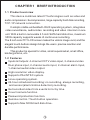
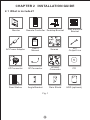
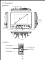
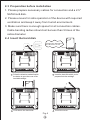
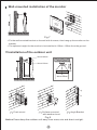
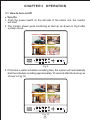
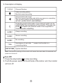
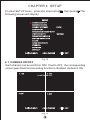
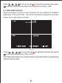
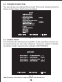
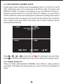
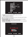
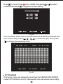
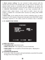
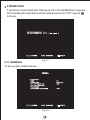
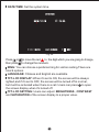
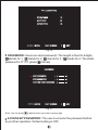
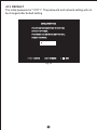
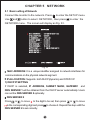
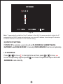
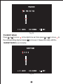
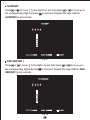
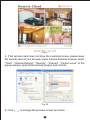
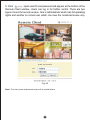
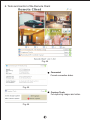
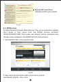
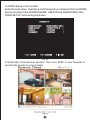
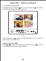
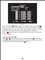
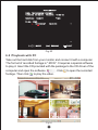
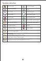
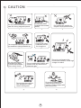
IVR-Q8
User's Manual
8 TFT-LCD COLOR
INTERCOM VIDEO RECORDER
LIST
CHAPTER 1 BRIEF INTRODUCTION
1.1 Product overview ..............................................................
1.2 Features ........................................................................
CHAPTER 2 INSTALLATION GUIDE
2.1 What is included? .............................................................
2.2 Description ............................................................
2.3 Preparation before installation ..................................................
2.4 Insert the hard disk ...............................................................
2.5 Installation ......................................................................
CHAPTER3 OPERATION
3.1 How to turn on/off ............................................................
3.2 Operation buttons .....................................................
CHAPTER 4 SETUP
4.1 Camera on/off ......................................................................
4.2 Record on/off ....................................................................
4.3 Covert function ....................................................................
4.4 Audio port ......................................................................
4.5 Recording frame rate ........................................................
4.6 Video quality ...............................................................
4.7 Recording schedule ..............................................................
4.8 Motion detection ................................................
4.9 Alarm setup .....................................................
4.10 Hard disk drive ....................................................
4.11 General .......................................................
4.12 Default ...............................................................................
CHAPTER 5 NETWORK
......................................................
5.1 Basic setting of Network
............................................................
5.2 Open HTTP port
.......................................................
5.3 Remote monitoring and control
...........................................................................
5.4 DDNS setup
CHAPTER 6 VIDEO PLAYBACK
..........................................................
6.1 Playback on monitor
..................................................
6.2 Playback with PC
1
1
2
3
4
4
5
7
9
10
11
12
12
13
13
14
15
17
18
19
22
23
27
28
32
34
36
CHAPTER 1 BRIEF INTRODUCTION
1.1 Product overview
This device combines latest IT technologies such as video and
audio compression / decompression, large-capacity hard disk recording,
TCP / IP network connection.
It adopts stable embedded LINUX operating system, integrates
video surveillance, audio/video recording and video intercom in one
unit. With a built-in removable 2.5 inch SATA hard disk drive, maximum
500G capacity supports weeks of continuous recording.
The 8 inch color TFT-LCD screen makes the vistors image vivid, and the
elegant touch-buttons design brings the users precise reaction and
durable performance.
This product is special for villas, small supermarket, small office,
kindergartens, etc.
1.2 Features
Inputs & Outputs: 4-channel CCTV video input, 2-channel video
Door phone input, 2-channel audio input, 2-channel alarm Input,
1-channel audio/video output.
High resolution video display.
Supports PAL/NTSC system.
Linux operating system.
24-hour scheduled recording: no recording, always recording,
and sensor(alarm/motion detection) recording.
Get recorded video from events list or by time.
Covert camera function.
Password protection function.
Remote control / Touch button operation.
Supports Max 500G hard disk drive.
CHAPTER 2 INSTALLATION GUIDE
2.1 What is included?
Monitor
Remote Controller Desktop Bracket
Wall-mounted
Bracket
User's
Manual
A/V
Output Line
AC Power Adaptor
User's
Manual
4P Connector
5P Connector
6P BNC
Connector
CD
Door Station
Angle Bracket
Rain Shield
HDD (optional)
Screws
Fig.1
2.2 Description
Monitor
2.5" HARD DISK CATRIDGE
8
VOICE
ADJUSTMENT
A/V OUT
POWER
SWITCH
LOUDSPEAKER
POWER
INDICATION
POWER
SUPPLY
TOUCH PANEL
OUTDOOR
STATION 2
OUTDOOR
STATION 1
TCP/IP
NETWORK
CAM 1
CAM 3
CAM 2
MIC
IR RECEIVER
SENSOR
DEVICE
CAM 4
Fig.2
Camera
Mic r ophone
Pinhole Lens
Infrared Light
Call Button
Loud Speaker
Fig.3
2.3 Preparation before installation
1. Please prepare necessary cables for connection and a 2.5"
SATA hard disk.
2. Please ensure for safe operation of the device with required
ventilation and keep it away from humid environment.
3. Make sure there is enough space for all connection cables.
Cable bending radius should not be less than 5 times of the
cable diameter.
2.4 Insert the hard disk
Please pay attention to
the direction of slot.
1
Follow the direction marked beside
the button to open the cover of the
hard disk catridge.
2
Insert the hard disk which you've
prepared into the cartridge.
3
Push down the hard disk.
4
Close the cover.
Fig.4
2.5 Installation
Wiring
POWER ADAPTOR
(AC 110
240V)
TCP/IP (NETWORK)
Fig.5
4-pin connector for outdoor station
1
4
2
3
1---- GND(Black)
3---- B+(Red)
2---- Video(Yellow )
4---- Audio(White)
Left view
5-pin connector for alarm device
5
1
2
4
3
1---- Alarm Out(Blue )
3---- Sensor 2(White)
5---- GND(Black)
2---- Alarm In(Brown)
4---- Sensor 1(Red)
Left view
6-pin connector for camera
1
6
2
5
3
4
Left view
1---- GND for Video(Black) 2---- Control(Blue)
3---- GND for Audio & Power(Brown)
4---- VDD(Red)
5---- Video In(Yellow)
6---- Aduio In(White)
Fig.6
Wall-mounted installation of the monitor
Fig.7
> Fix the wall-mounted bracket on the wall with 4 screws, then hang up the monitor on the
bracket.
> The optimum height for the monitor to be installed is 130cm~150cm from the ground.
Installation of the outdoor unit
about 180cm
about 130cm
about 50cm
Wall
Wall
Wall
1
Flush-mount
2
Surface-mounted
with weather hood
3
Angle Bracket
Fig.8
Notice: Please keep the outdoor unit away from snow, rain and direct sunlight.
CHAPTER 3 OPERATION
3.1 How to turn on/off
Turn On
1. Push the power switch on the left side of the indoor unit, the monitor
will start.
2. The monitor shows quad monitoring at start up as shown in Fig.9 after
system check.
1
2
3
4
2010/10/21
22:20:51
Fig.9
3. If the time is within schedule recording time, the system will automatically
start the schedule recording approximately 10 seconds after the boot up as
shown in Fig.10.
1
2
3
4
A-REC
*75%
2010/10/21
Fig.10
22:20:51
5. Description of display
1,2,3,4
Channel Number
Video recording status.
Red dot means recording.
Channel with audio input.
Red icon means recording and white one means no recording.
The recording status can be changed in the
SETUP->AUDIO PORT->RECORDING.
Outputting audio information. One channel audio can be
outputted by the microphone of the monitor. The user can
press to select one channel audio to be outputted or
close the audio outputting.
A-REC
Always recording.
S-REC
Sensor recording.
N-REC
No recording.
*75%
Used space of hard disk. "*" means that the disk is in
overwriting status.
DATE/TIME System date/time.
Note: Your previous settings of the monitor will remain the same when it's restarted from
power cut or shut off.
Turn Off
1. Press the stop button to stop recording.
2. Push the power switch on the left side of the indoor unit, the monitor
will turn off.
3.2 Operation buttons
IVR-Q8
Intercom Video Recorder
Fig.11
NO
NAME
ICON
OPERATION
NO
NAME
Full Screen Display of
Channle 1/Number 1
6
Play
Full Screen Display of
Channle 2/Number 2
1
Display
2
Setup
3
Audio
Channel
4
5
OPERATION
Play/Pause
Up
Full Screen Display of
Channle 3/Number 3
Full Screen Display of
Channle 4/Number 4
ICON
Down
7
Move/
Confirm
Left/Backward
Quad Display
Right/Forward
Enter/Exit Setup
Choose/Confirm
Switch/Close
Audio Output
8
Talk/
Monitoring
REC
Start/Stop Recording
9
Unlock
Unlock
Stop
Stop
10
Display
On/Off
Turn On/Off
Monitor Display
Talk/Monitoring/
Turn on Monitor Display
Note: Buttons on the remote controller are same functions as on monitor buttons, except the
(On/Off) on the remote controller.
CHAPTER 4 SETUP
To enter SETUP menu, press the stop button
following screen will display:
, then press
.The
SETUP
CAMERA ON/OFF
RECORD ON/OFF
COVERT CHANNEL
[ OFF ]
AUDIO PORT
RECORDING FRAME RATE
VIDEO QUALITY
NORMAL
RECORD SCHEDULE
MOTION DETECTION
ALARM
HARD DISK DRIVE
GENERAL
NETWORK
DEFAULT
MOVE
CHOOSE
EXIT
Fig.12
4.1 CAMERA ON/OFF
Each channel can be set ON or OFF. If set to OFF, the corresponding
screen goes black and recording function is disabled. Default is ON.
1
2 ON
ON
CAMERA ON/OFF
3 OFF
4 OFF
MOVE
CHOOSE
Fig.13
EXIT
Press
to move the red to select the channel, then press
to set the camera connected to this channel to be ON or OFF.
4.2 RECORD ON/OFF
Video recording function of each channel can be enabled or disabled
seperately. If it is set to OFF , the screen will keep showing the surveiled
scene, but it will not be recorded.
1
2 ON
ON
RECORD ON/OFF
3 OFF
4 NO CAM
MOVE
CHOOSE
EXIT
Fig.14
Press
to move the red to select the channel, then press
to set recording function ON or OFF.
NO CAM means there is no camera being connected with the corresponding
channel of the monitor.
4.3 COVERT FUNCTION
You can choose one channel to be covert. This covert channel will not be
shown on the screen, but it can be recorded.
SETUP
CAMERA ON/OFF
RECORD ON/OFF
COVERT CHANNEL
[ OFF ]
AUDIO PORT
RECORDING FRAME RATE
VIDEO QUALITY
NORMAL
RECORD SCHEDULE
MOTION DETECTION
ALARM
HARD DISK DRIVE
GENERAL
NETWORK
DEFAULT
MOVE
EXIT
CHOOSE
Fig.15
4.4 AUDIO PORT
Two channels of audio input are available. Audio acquisition devices can
be connected to any two video channels. Users can enable or disable
recording of audio separately by setting the RECORDING.
AUDIO PORT
AUDIO PORT 1 - VIDEO CHANNEL [
AUDIO PROT 1 - RECORDING
AUDIO PROT 2 - VIDEO CHANNEL [
AUDIO PROT 2 - RECORDING
MOVE
CHOOSE
1 ]
[ YES ]
2
]
[ YES ]
EXIT
Fig.16
Note: Microphone of the monitor is an audio acquisition device for audio port 1.
4.5 RECORDING FRAMET RATE
Frame rate of each channel can be separately set to 1,2,3,4,5,6,12,16,25
FPS. Total frame rate of four channels is 50 FPS for PAL TV system and
60FPS for NTSC TV system. For example, if you set 16FPS for channe 1,
channel 2 and channel 3 for a monitor in PAL TV system, you can choose
1FPS or 2FPS for channel 4 and keep the selected recording frame rate of
other channels same, however, if you want to set the frame rate of channel
4 to a option more than 2FPS, the frame rate of other channels will be
reduced automatically.
1
2 16 FPS
16 FPS
RECORDING FRAME RATE
TOTAL 32 FPS
3 16 FPS
4 2 FPS
MOVE
CHOOSE
EXIT
Fig.17
Press
press
to move the red to the channel to be set, then
to set the recording frame rate of this channel to a proper value.
4.6 VIDEO QUALITY
There are three options(HIGH, NORMAL and LOW) for video quality of
recording. The better recording quality you choose, the more disk space it
takes.
SETUP
CAMERA ON/OFF
RECORD ON/OFF
COVERT CHANNEL
[ OFF ]
AUDIO PORT
RECORDING FRAME RATE
VIDEO QUALITY
NORMAL
RECORD SCHEDULE
MOTION DETECTION
ALARM
HARD DISK DRIVE
GENERAL
NETWORK
DEFAULT
MOVE
EXIT
CHOOSE
Fig.18
Press
button to select a preferred video quality of recording .
4.7 RECORDING SCHEDULE
Users can schedule the recording hour by hour for the whole day. The three
options of recording are as following,
> NO RECORDING: Video from the CCTV cameras will not be recorded.
> ALWAYS RECORDING: Video will always be recorded.
> SENSOR RECORDING: Video will be recorded when motion is detected
or an alarm event occurs.
RECORD SCHEDULE
AM
0
3
6
9
PM
0
3
6
9
NO RECORDING
ALWAYS RECORDING
SENSOR RECORDING
MOVE
CHOOSE
Fig.19
EXIT
Press
press
to move the red
to set the recording mode.
to select the time frame, then
4.8 MOTION DETECTION
MOTION DETECTION
RECORD TIME
10
DETECTED CHANNEL/AREA
OFF
IR TRIGGER
MOVE
CHOOSE
EXIT
Fig.20
RECORD TIME
Set the recording time when a motion event occurs in the SENSOR
RECORDING mode.
DETECTED CHANNEL/AREA
Users can turn ON or OFF the motion detection function of each channel .
Press or to move the red to select the channel, then press to set
the motion detection ON or OFF.
DETECTED CHANNEL/AREA
MOVE
CH-1 [ ON ]
AREA
CH-2 [ ON ]
AREA
CH-3 [OFF]
AREA
CH-4 [OFF]
AREA
CHOOSE
Fig.21
EXIT
Press
to move the red to the AREA, then press
a channel and press
to trigger the motion setting.
or
to select
DETECTED CHANNEL/AREA
MOVE
CH-1 [ ON ]
AREA
CH-2 [ ON ]
AREA
CH-3 [ ON ]
AREA
CH-4 [ ON ]
AREA
CHOOSE
EXIT
Fig.22
Four sensitivity levels can be selected and the sensitivity increases with
the number rising. Press
to select the grid. Then press
to change the sensitivity level.
Fig.23
IR TRIGGER
Only human motion can activate the recording in the SENSOR RECORDING
mode if IR TRIGGER is set ON. Otherwise all motion will activate the recording.
4.9 ALARM SETUP
ALARM SETUP
VIDEO LOSS
ALARM DEVICE
ON
MOVE
CHOOSE
EXIT
Fig.24
VIDEO LOSS
In the monitoring status,if the video cable connection is not good, the
indoor unit will alarm with beep sound. Users can set it ON or OFF.
ALARM DEVICE
ALARMDEVICE
DEVICE
ALARM
SENSOR-1 CHANNEL-1
SET
OPEN
SENSOR-1 CHANNEL [1]
SET
[ OPEN ]
ALARM TIME
SENSOR-2
CHANNEL [2]
SET
[CLOSE]
ALARM TIME
MOVE
[ 15 ]
CHOOSE
Fig.25
EXIT
> Alarm sensor setting: You can connect 2 alarm sensors with the
monitor and set them to be bonded with 2 of the 4 CCTV channels. If an
external alarm sensor is connected and it's triggered by an event, the
monitor will alarm with beep sound and also activate the recording if it's
in SENSOR RECORDING schedule. If you have connected with an
external alarm output device, it will send an alarm. Users can also
enable or disable the connected alarm sensors by setting them OPEN
or CLOSE.
> Alarm Time: It's for setting the time of alarm outputting when an alarm
event occurs. OFF means no response to the alarm event and CONT means
constantly response to the alarm event till someone stop it manually.
4.10 HARD DISK DRIVE
HARD DISK DRIVE
ST9408221AS
HDD CAPACITY
HDD USED
OVERWRITE ENABLED
FORMAT HDD
MOVE
CHOOSE
40030MB
23789MB 59%
[YES]
EXIT
Fig.26
HDD information
> ST9408221AS: Hard disk model.
> HDD CAPACITY: The capacity of current hard disk.
> HDD USED: The occupation of hard disk space, displayed in
percentage.
OVERWRITE ENABLED
If it is set to YES, the system will automatically overwriter the earlier
footage when the storage is full.
FORMAT HDD
Format the current hard disk. Password set in the GENERAL is required
for formatting the hard disk and the initial password is 111111 (press
6 times).
ENTER PASSWORD
MOVE
6 :[
]
EXIT
CHOOSE
Fig.27
4.11 GENERAL
To set system-related issues.
GENERAL
DATE/TIME
RING
LANGUAGE
TFT - LCD DISPLAY
TFT - LCD SETTING
PASSWORD
ACCESS BY PASSWORD
MOVE
CHOOSE
Fig.28
06
ENGLISH
ON
OFF
EXIT
DATE/TIME: Set the system time.
DATE/TIME
2010 / 10 / 18
MOVE
17 : 12 : 36
CHOOSE
EXIT
Fig.29
Press or
then press
to move the red
to the digit which you are going to change,
to change the numbers.
RING: You can choose a preferred ring for visitors calling.There are
total 9 options.
LANGUAGE: Chinese and English are available.
TFT-LCD DISPLAY: When it's set to ON, the screen will be always
lighted,and if it's set to OFF, the screen will be turned off in normal,
but it will be activated when there is a call. Users can press to open
the screen display when it's turned off.
TFT-LCD SETTING: Users can adjust BRIGHTNESS , CONTRAST
and SATURATION of the screen display to a proper value.
TFT - LCD SETTING
BRIGHTNESS
10
CONTRAST
08
SATURATION
08
MOVE
CHOOSE
EXIT
Fig.30
PASSWORD: Users can reset password. The length is fixed to 6 digits,
stands for 1,
stands for 2,
stands for 3,
stands for 4. The initial
password is 111111 (press 6 times).
PASSWORD
OLD PASSWORD
:
<
>
NEW PASSWORD
:
<
>
CONFIRM NEW PASSWORD:
<
>
MOVE
CHOOSE
EXIT
Fig.31
Note: You can press
to delete when you enter a wrong digit.
ACCESS BY PASSWORD: The user must enter the password before
any further operation. Default setting is OFF.
4.12 DEFAULT
The initial password is "111111". The password and network setting will not
be changed after default setting.
DEFAULT SETTING
PLEASE ENTER PASSWORD TO RESTORE
DEFAULT SETTINGS,
PASSWORD AND NETWORK SETTING WILL
REMAIN THE SAME.
MOVE
CHOOSE
Fig.32
EXIT
CHAPTER 5 NETWORK
5.1 Basic setting of Network
Connect the monitor to the network. Press
Use
and
to enter the SETUP menu.
button to select NETWORK, then press
to enter the
NETWORK menu. The screen will display as Fig. 33.
NETWORK
MAC ADDRESS...
<00:BB:4B:E8:21:A8>
IP ALLOCATION..
[DHCP]
IP ADDRESS.......
<0.0.0.0>
SUBNET MASK...
<0.0.0.0>
GATEWAY...........
<0.0.0.0>
DNS SERVER 1..
<0.0.0.0>
DNS SERVER 2..
[0.0.0.0]
HTTP PORT........
[
80] 80,1024-49151
USER SETUP.....
DDNS SETUP.....
MOVE
CHOOSE
EXIT
Fig.33
MAC ADDRESS: It is a unique identifier assigned to network interfaces for
communications on the physical network segment.
IP ALLOCATION: Supports both DHCP(dynamic) and STATIC IP.
1) DHCP IP SETTING
If DHCP is selected, IP ADDRESS, SUBNET MASK, GATEWAY
and
DNS SERVER 1 will be obtained from the DHCP server automatically. Users
can set the DNS SERVER 2 optionally.
DNS SERVER 2
Press
or
to move
to the digit to be set, then press
to the corresponding digit and press
DNS SERVER 2 is set correctly.
or
to move
to choose it. Repeat this step untill the
DDS SERVER 2
0.0.0.0
0
1
2
3
MOVE
CHOOSE
EXIT
Fig.34
Note: To guarantee the stability of the IP address in the LAN. It's recommended to obtain the IP
automatically by DHCP mode and write down your current IP address, then change IP allocation
to static and enter IP information in the network setting.
2) STATIC IP SETTING
If STATIC IP is selected, users should set IP ADDRESS, SUBNET MASK,
GATEWAY and DNS SERVER 1 manually. DNS SERVER 2 can be set optionally.
IP ADDRESS
Press
or
to move
to the digit to be set, then press
to the corresponding digit and press
ADDRESS is set correctly.
or
to move
to choose it. Repeat this step untill the IP
IP ADDRESS
192 . 168 .18 . 102
0
1
2
3
MOVE
CHOOSE
EXIT
Fig.35
SUBNET MASK
Press
or
to move
to the digit to be set, then press
the corresponding digit and press
to move
to choose it. Repeat this step untill the
SUBNET MASK is set correctly.
SUBNET MASK
0.0.0.0
0
1
2
3
MOVE
or
CHOOSE
Fig.36
EXIT
to
GATEWAY
Press
or
to move
to the digit to be set, then press
the corresponding digit and press
or
to move
to
to choose it. Repeat this step untill the
GATEWAY is set correctly.
GATEWAY
0.0.0.0
0
1
2
3
MOVE
CHOOSE
Fig.37
DNS SERVER 1
Press
or
to move
EXIT
to the digit to be set, then press
the corresponding digit and press
to move
to
to choose it. Repeat this step untill the DNS
SERVER 1 is set correctly.
DDS SERVER 1
0.0.0.0
0
1
2
3
MOVE
or
CHOOSE
Fig.38
EXIT
DNS SERVER 2
Press
or
to move
to the digit to be set, then press
the corresponding digit and press
or
to move
to
to choose it. Repeat this step untill the DNS
SERVER 2 is set correctly.
DDS SERVER 2
0.0.0.0
0
1
2
3
MOVE
CHOOSE
EXIT
Fig.39
Note: Please restart your monitor after network setup.
5.2 Open HTTP port
It's necessary to open the HTTP port of the monitor before the users can
get remote access to it.
1. Assign a port number to be opened
Optional HTTP PORT is 80,1024 to 49151. Press or to move
to the digit to be set, then press
or
to move
to the
corresponding digit and press
to choose it. Repeat this step
untill the HTTP PORT is set correctly. The default port is 80.
HTTP PORT
0
1
2
3
MOVE
OK CHOOSE
EXIT
Fig.40
2. Open the HTTP PORT on a router
It might be done in different way to open an HTTP PORT on different
types of routers. For a specific router, please contact the vendor to get
the detail.
5.3 Remote monitoring and control
1. Open an IE browser, enter the monitor's IP address such as
http://192.168.18.101:6666 in the LAN or your WAN IP such as
http://113.110.152.49:6666 in the address bar. First visit will be prompted
to install plugin, select "Yes" to install it. Installation will begin automatically
after downloading. If the plugin does not download automatically, please click
"Download" in "If the plugin can not download, click here". Double click the
downloaded file to install it when the download is finished.
Note:The port number can be omitted if you use the default port 80, for example
http://192.168.18.101.
2. After the plug-in installation, it will pop-up a "Remote Client" window as
Fig.41 shows. If not, please close and restart IE then input the
network address correctly.
Fig.41
3. If the remote client does not show the monitored scene, please lower
the security level of your browser. Open Internet Explorer browser, select
"Tools" - "Internet Options" - "Security" - "Internet" - "Custom Level". In the
popup window, open all the ActiveX plugins and controls.
Fig.42
4. Click
to enlarge the preview screen two times.
5. Click
, input user ID and password will appear at the bottom of the
Remote Client window. Users can log in for further control. There are two
types of users for remote access. One is administrator which has full operating
rights and another is normal user which can view the monitored scene only.
Fig.43
Note: The user name and password are all in capital letters.
6. Tools and control of the Remote Client
Fig.44
Connected
Current connection status.
Fig.45
Capture Tools
For capturing images and video.
Fig.46
Remote DVR Control Panel
Remote control to your monitor.
Fig.47
5.4 DDNS setup
To setup Dynamic Domain Name Service. The user is required to register
and create a host name from the DDNS service provider
WWW.DYNDNS.COM. Then enter user ID(user name), password and
domain name obtained in the DDNS SETUP of the monitor.
1. Visit website http:// www.dyndns.com.
Fig.48
2. Sign up an account and create a host name such as
remoteview. dyndns - free. Com.
3. DDNS Setup in the monitor
Enter the host name, Username and Password you obtained from the DDNS
service provider in the DOMAIN NAME, USER ID and PASSWORD of the
DDNS SETUP menu as Fig.49 shows.
DDNS SETUP
DDNS PROVIDER
[WWW.DYNDNS.COM ]
DOMAIN NAME
[ REMOTEVIEW .D... ]
USER ID
[ XXXXXXX
]
PASSWORD
[ XXXXXXX
]
MOVE
CHOOSE
EXIT
Fig.49
4. Enter http: //remoteview. dyndns - free. com: 6666 in your browser to
get remote access to your monitor.
Fig.50
CHAPTER 6 VIDEO PLAYBACK
6.1 Playback on monitor
Press the stop recording key , then press the play key
will automatically play the latest video clip.
1
2
3
4
P A LY
2010/10/21
, the system
22:20:51
Fig.51
Press the menu key to enter the VIDEO SEARCH menu. Users can
search video by event or time.
Search video by EVENT
Press or to select the search type EVENT, then press
it. The display will change to Fig.52 shows.
to choose
VIDEO SEARCH
HDD: TOSHIBA MK 1665GSX
10/04/20 22:20:22 - 10/05/08
15:58:33
SEARCH:
TIME
EVENT
PLAY: EVENTS
00010
00009
00008
00007
00006
00005
00004
00003
00002
00001
00000
MOVE
C
T
C
T
T
T
S
C
C
T
T
2010/05/08
2010/05/07
2010/05/06
2010/05/04
2010/05/01
2010/04/29
2010/04/27
2010/04/26
2010/04/22
2010/04/21
2010/04/20
CHOOSE
15:58:29
18:25:32
13:05:06
06:14:36
03:05:48
09:59:14
16:14:57
01:56:37
14:52:36
23:45:24
22:20:22
EXIT
Fig.52
Users can press
or
to select from different events, and press to
play. In the event list, "T" stands for video clip recorded in always
recording mode., "S" stands for video clip recorded in sensor recording
mode and "C" stands for video clip recorded when a visitor call.
When a appears on an event, it presents that this event is accompanied
by power failure.
Search video by TIME
Press or to select the search type TIME, then press
to choose it.
The display will change to Fig.53 shows. Users can input the time which
he wants to check the video and press to play.
VIDEO SEARCH
HDD: TOSHIBA MK 1665GSX
10/04/20 22:20:22 - 10/05/08
15:58:33
SEARCH:
TIME
EVENT
PLAY: TIME
2010/05/07
MOVE
18:25:32
CHOOSE
EXIT
Fig.53
6.2 Playback with PC
Take out the hard disk from your monitor and connect it with a computer.
The format of recorded footage is ".MCG". It requires a special software
to play it. Insert the CD provided with the package to the CD driver of the
computer and open the software
.Click to open the recorded
footage. Then click
to play the video.
1
2
3
4
2010/10/21
PAUSED
Fig.54
22:20:51
Operation instruction
MCG file dump
Reverse Playback
Always Top Window
Pause
50% Screen
Forward Playback
100% Screen
Jump forward 10 Sec
150% Screen
Jump forward 60 Sec
Close
Play frame by frame backward
Open another MCG file
Play frame by frame forward
Jump back 60 Sec
Record
Jump back 10 Sec
Capture [BMP]
Switching storage device.
Preferences
C hange the application ' s default setting.
Audio Output Setting / Volume control
Move the
window
Drag the window by its part below title bar to move it.
CAUTION
Do not put the monitor and camera
near the strong magnetic places.
Do not spray water
or liquid to the monitor
directly.
1
Do not drop the monitor or
subject it to physical shocks.
3
2
Do not expose monitor and camera to
the sunshine or strong reflection ray.
Plug off the power
cord while not use
for a long time.
5
4
Do not insert plugs into
a socket to be filled.
(This will be caused a
fire or short circuit)
Do not installed the monitor and
camera near any ammonia or
poisonous gas.
6
7
Do not try to dismantle the
monitor and camera, as the high
voltage is inside it.
8
ent
terg
De
Do not try to dismantle the
machine while failure to
function. Please contact with
the local service.
Do not wipe the machine
with detergent or other
chemic impregnant.
10
38