1
Proceedings of the 10th WSEAS International Conference on AUTOMATION & INFORMATION
HMI and Control Loops over Serial Line Communication Channel with
MODBUS protocol for Combinatorial Weigher at Potato Chips
Production Line
LAVDIM KURTAJ, VJOSA SHATRI
Department of Automation
University of Prishtina
Bregu i Diellit p.n., 10000 Prishtina
KOSOVA
{lavdim.kurtaj, vjosa.shatri}@fiek.uni-pr.edu
Abstract: - Potato chips are product with irregular forms with complex flow dynamics. Packing with narrow
tolerance is done by combinatorial weighing machine. For controlling this complex machine it is of great
importance to have well designed human-machine interface (HMI). To minimize human intervention on
machine operation of great importance is quality of its control algorithm. To gain an insight into the process of
vibratory conveying and combinatorial weighing of potato chips experimental on-line setup was created. Setup
contains refurbished combinatorial weigher and personal computer (PC) with network control structure. First, a
short introduction to the chain of supplying, weighing and packing at potato chips production line is given. It is
described briefly principle of combinatorial weighing. Next, experimental setup was described, from
constructive parts, to hardware and software implementation. RS485 serial communication line with MODBUS
protocol was used for networking master and three slave control units. Application software and implemented
functions for making flexible development system are presented. HMI and MODBUS protocol were
implemented with Visual Basic. Finally, tests results are given and show flexibility of setup in implementing
real-time closed-loop control over MODBUS communication channel for combinatorial weigher at potato chips
production line.
Key-Words: - Combinatorial Weigher, Potato Chips, Vibration Feeder, HMI, MODBUS, Visual Basic
acquiring weigh data from multiple weighing heads,
calculating sums of all possible combinations and
selecting the best one, i.e. combination that gives
sum weigh closest to "at-least" weigh from upper
side [4] [5]. Second designation, multihead weigher,
must imply combinatorial process of weigh data to
be part of this grup.
Motivation for this work was complexity of dynamic
of this simply stated principle of operation and lack
of literature that treats whole process from product
supply to weighted pack product. Aim was to create
a platform for gathering data from real process, for
modelling and simulatins [6], and for testing
different control strategies that will improve
accuracy and speed, reduce downtime and giveaway
and in the same time having all the functionality of
modern Human-Machine Interface (HMI) [7]. Since
control loops will go through communication
channel it will be a good platform for testing
industrial communication and real-time control over
network with Master-Slave topology. Selected
protocol was MODBUS over Serial Line [8] [9]. As
a physical layer 2-Wire RS485 was adopted, as
1. Introduction
Most of food manufacturing industries as last part of
production line have some sort of packing machine.
Quality demands on producer side now days are
high. One of mandatory requests is real pack weigh
and one marked on package and "at-least" rule
applies in this case. On the other side, "overweighted" packages are in disfavor viewed from
producer side. Production line is continuous chain of
machines, from preparation of raw materials to
handling of already packed final product.
Throughput of each segment of the chain must be
compatible with requested capacity. Weighing final
product for packing with necessary speed, while
fulfilling "at-least" rule and minimizing "overweight" part, imposes specific measuring equipment.
This part of process is even harder if size and weight
of product particles varies in broad range and with
complexity of flow mechanism of products with
irregular forms. Member of this category are Potato
Chips range of products.
Solution for weighing this category of products is
Automatic Combination Weigher [1], or Multihead
Weigher [2] [3]. Core of combinatorial weighing is
ISSN: 1790-5117
220
ISBN: 978-960-474-064-2
Proceedings of the 10th WSEAS International Conference on AUTOMATION & INFORMATION
Conveyor is driven by Induction AC motor and
usually is controlled by simple On/Off algorithm.
For improved performance and reduction of wear-off
motor was supplied by Variable Frequency Drive
(VFD) [11]. VFD is equipped with local control
panel and with MODBUS module. It is one of slaves
in the network.
Conveyor
RF1
CF
RF5
HH1
WH1
MH1L
From
Flavoring
Part
MH1R
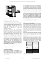
2.2 Combinatorial Weigher
Weigher is composed of three functional groups,
Fig.1 . First, upper group, is product supply side.
Main part of this group is central conical body that's
vibrating surface of central vibratory feeder (CF). In
middle there are Nh measuring heads. Each head has
one horizontal radial vibratory feeder (RFi), one
holding hopper (HHi) with controllable door at its
bottom, one weighing hopper (WHi) with two
independently controllable doors (left and right), and
two memory hoppers (MHiL and MHiR). Third
function group is exit unit with collecting chute and
discharge hopper (DH) as its parts. DH has
controllable door for discharging product on request
from packing machine.
CF serves as a distributer of incoming product to Nf
heads. Rate of product flow is controlled by intensity
of vibrations. Product that leaves CF falls to
corresponding radial vibratory feeders surface.
Perimeter of CF is divided in Nh equal sectors.
Product on suface of RFi is transported and supplied
systematically [12] [13] to HHi.When weigh is free
for new measurement, content of HHi as a batch is
released to WHi and weight data are acquired. If one
of MHs is empty, corresponding door is opened and
product goes to memory hopper.
Weight data from 2*Nh MHs serve as input to
combinatorial process [4]. In this process are
calculated sums of all possible combinations hCk for
k=1 to h. Results are compared with set weight and
with maximal tolerable weight. From values in this
range is selected one closest to the set weight.
Selected value is sum of k weights from selected
MHs.
If DH is empty selected MHs are opened and their
product is collected to DH. Now exit unit is ready for
supplying a batch of product to packing machine.
Packing machine is informed and unit waits for
request signal.
When exit unit receives request from packing
machine it will open doors of DH from where
product will go to prepared pack. Upon release of
product exit unit will be ready for new batch.
Collecting Chute
DH
Packing Machine
Fig.1 Production Chain: Conveyor - Combinatorial
Weigher - Packing Machine
industry widely used bidirectional,
transmission line standard [10].
balanced
2. Supplying, Weighing and Packing
Chain
Potato chips production line uses potatoes as
incoming raw material. After preparation phase,
potatoes get sliced up. Slices enter the frying oven
where they get fried and dryed of excessive fry fat.
Next stage is visual inspection and removal of out of
tolerance fryed and other defective slices. Flavoring
is done in next step and again followed with visual
inspection for proper level of flavoring and if
necessary removal of over flavored.
At this stage product is ready for consumption and
for quality of product it important to reduce the time
of contact product- free air. Here starts the chain of
Supplying-Weighing-Packing. Continuous flow of
product from previous stages is delivered to
supplying conveyor, Fig.1, for transporting it to the
entrance of combinatorial weigher. Weighing,
finding the best final weight and making it ready for
packing machine is duty of combinatorial weighing
machine. Final weight that is waiting will be released
to packing machine on its request.
2.1 Supply Conveyor
Transporting product from near floor level to near
ceiling level to supply position of combinatorial
weigher is done with conveyor of bucket type. Its
state of operation is controlled by the level of
product in receiver side, conical part marked by CF
(Circular Vibratory Feeder) in Fig.1.
ISSN: 1790-5117
221
ISBN: 978-960-474-064-2
Proceedings of the 10th WSEAS International Conference on AUTOMATION & INFORMATION
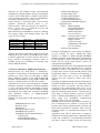
It is a multipoint serial line bus and requirements of
[8] are fulfilled. Connection of Line Termination
(LT) impedances (resistor 150Ω/0.5W) are placed at
both ends. Line polarization resistors PU (Pull-Up)
and PD (Pull-Down) with value 650Ω were used.
Three passive taps with two IDv (Distributor type
Derivation Interface) were used. First tap is used for
connection of Slave1 (CPU1) and Slave2 (CPU2).
Signal ground connection to protective ground and
one of LT are placed at this tap. One IDv of second
tap is used for connection of Slave-VFD to bus.
Third tap is connection point of Master to bus.
Second LT is placed at this tap. Unconnected second
IDv of last two taps may be used for diagnostic
monitoring activities on bus.
Trunk cable lengths were 10m and 30m and are not
critical for used Baud Rate of 19200bps.
Slave3 (VFD): Addr=40H
D
R
Slave2 (CPU2): Addr=20H
Master (PC-HMI)
D
D
R
R
D
D1 D0
R
Common
Slave1 (CPU1): Addr=10H
+5V
PU
LT
PD
LT
Fig.2 RS485 Network Toplogy
3. Experimental On-Line Setup
For creation of experimental setup a second handed
automatic combination weigher was used. Weigher
was an old model, K723A [14], of Anritsu [1]. It is
an 8-head weighing machine. Declared speed was 60
to 120 packs/minute. Weighing range is 50g to
2000g and accuracy xmean=1 to 1.5g. All
specifications are dependent on product and
installation conditions.
Mechanical, pneumatic and electromagnetic
vibratory feeders were tested with positive result.
Electronics was defective and if was found that
almost all EPROMs had experienced aging caused
data corruption. Analog and digital I/O units
(CH1~CH4, CH5~CH8, A/D, CONT, I/O,
F.DRIVE) were functional and used as such. ALU
unit that was responsible for combinatorial
calculations was not used. Z80CPU unit is dual
microprocessor board with 2 Zilog Z80H-CPU
microprocessors operating at 8MHz clock [15]. They
have possibility of using shared-memory block,
which is not used. Two microprocessors now
communicate only over network. One functions as a
Slave1 and other as a Slave2. Keyboard and display
(KEY&DISP) was not used too.
Functions of combinatorial calculations and HMI are
done with a Personal Computer (PC). PC is Master
of the network. It is an PIV PC at 1GHz, with
512MB RAM and 20GB HDD.
3.2 Protocol and Data Model
Selected Protocol was MODBUS over serial line in
RTU transmission mode. If compared to OSI model
with 7 layers, this protocol takes place at level 2
(Data Link) and level 7 (Application) [8]. Protocol
provides client/server communication. Protocol Data
Unit (PDU) is defined by protocol specification.
Additional fields are introduced to create Application
Data Unit (ADU) and this part is bus and network
dependent.
PDU has Function code field and Data field. Over
serial line communication appends preceding
Address field and ending CRC field. ADU in this
case is referred as "MODBUS frame over Serial
Line" [8].
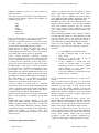
Frame for RTU mode is shown in Fig.3. Address
field has one byte. Valid slave numbers are 1-247.
One byte Function code field defines type of request
from client. There are three types of requests: Public,
User-Defined and Reserved [9] [16]. Public
≥ 3.5 char
Address
Function
CRC Check
8 bits
8 bits
Byte 1 x 8 bits
Byte 2 x 8 bits
...
Byte N x 8 bits
16 bits
End
≥ 3.5 char
Data
3.1 Network Topology
Physical layer of network is implemented as "2Wire" electrical interface in accordance with
EIA/TIA-485 standard [10]. Only one driver can be
active at any time. Network topology with all actors
is given in Fig.2.
ISSN: 1790-5117
Start
Fig. 3 RTU message frame
222
ISBN: 978-960-474-064-2
Proceedings of the 10th WSEAS International Conference on AUTOMATION & INFORMATION
functions are well defined, unique and publically
documented. Function defines structure and number
of bytes in Data field and it is variable. CRC field is
error checking field and is result of "Redundancy
Checking" calculations. It is 2 bytes wide.
Silence interval ≥3.5 character times serves as frame
separator. Inter-frame allowed silence is ≤1.5
character times. This time intervals are marked t3.5
and t1.5. In our case t3.5=1/19200*11*3.5=2ms and
t1.5=1/19200*11*1.5=0.859ms.
Data abstraction in MODBUS is done by defining
four primary tables with defined Object type and
Type of access, Table 1.
Primary table
Discrete Input
Coils
Input Registers
Holding Registers
Object type
Single bit
Single bit
16-bit word
16-bit word
- 04 Read Input Registers
- 05 Write Single Coil
- 06 Write Single Register
- 15 Write Multiple Coils
- 16 Write Multiple Registers
- 23 Read/Write Multiple Registers
- Application part
- CPU1: - Main Weighing
- Weight Measurement
- Weigh Calibrations
- Read Temperatures
- Low-Level Tests
- CPU2: - Circular Feeder Control
- Radial Feeder Control
- Hopper Control
- Conveyor Control
- Handshaking with Packer
- Low-Level Tests
- Firmware Development
Type of access
Read-Only
Read/Write
Read-Only
Read/Write
Table 1. Four primary tables of MODBUS.
Firmware Development is used during development
of new software for slaves. During this phase
software is loaded in RAM through MODBUS
channel. Functions from RAM can be called and test
for functionality. Content of RAM is protected with
battery, but for safety reason mature versions are
reprogrammed in EPROM.
Following the RESET, CPU tests EPROM and RAM
content with same CRC algorithm that is used for
MODBUS protocol. Hardware tests of peripherals
are done next. If tests are passed with positive result
Initialization phase is executed and Watchdog is
started. CPU will listen on bus for MODBUS
requests and will respond to those with correct
address.
Watchdog is implemented in hardware and waits for
periodical attention from CPU. It is physically under
control of CPU2. In software part two levels of
watchdog were implemented. First level is for
watching for failures in handshaking between CPU1
and CPU2 through shared memory. Currently this is
only usage of shared memory resources. Second
level is watching handshaking of CPU1 / Master /
CPU2 chain over MODBUS communication
channel. Used level is user selectable.
MODBUS RTU protocol and Function execution is
part of interrupt service routines of serial port and
periodic timer. Events generated from serial port and
timer guide transitions of stateflow. After receiving
error-free request it is executed and response is sent
to Master.
Application part runs in Main body of program.
Transitions of main program may be generated from
events and conditions of corresponding functional
unit that it controls. Higher levels of control may
Address for data in each table is from 0 to 65536.
Mapping from data address of MODBUS data model
to device application is device specific and can be
freely selected. Overlapping between tables is
possible, giving us e possibility of accessing same
data in different formats.
3.3 Slave1 and Slave2 Application Software
Microprocessor for both slaves is Z80H-CPU,
member of 8-bit family of microprocessors initially
produces by Zilog. They are operating at 8MHz
clock. Hardware system is has 8kB RAM/32kB
EPROM and possibility of using another 8kB RAM
block as a shared memory for both CPU systems.
Applications for slaves were developed in Assembly
Language. Structure of software is based in stateflow
as very convenient model for developing real-time
event-driven software [17]. Model followed during
development was subset that resembles modelling
with Stateflow toolbox in Matlab/Simulink
environment [18].
EPROM was programmed with following blocks of
software:
- EPROM/RAM CRC Tests
- Hardware Tests
- Initialization
- Watchdog (software part)
- MODBUS RTU protocol
- MODBUS Function implementation
- 01 Read Coils
- 02 Read Discrete Input
- 03 Read Holding Registers
ISSN: 1790-5117
223
ISBN: 978-960-474-064-2
Proceedings of the 10th WSEAS International Conference on AUTOMATION & INFORMATION
influence transition process by data written on
specific registers.
CPU1 has 9 processes working in time-shared bases.
Global process follows requests from Master for
operation conditions:
Software in Master side was developed in Visual
Basic programming language with some native
Win32 API calls. It contains two main software
parts: HMI part that handles interaction with user
and MODBUS Master protocol implementation.
MODBUS protocol part was implemented as time
triggered polled stateflow. Two freeware modules
were used. Module ccrpTmr6 [19] was used for
precise fast responsive time triggering. For serial
port communication functions from CommIO [20]
module were used.
When transmitting, RS485 driver must be enabled.
For this function usually is used DTR line of serial
port, but during tests it was found that delay in
releasing driver was not tolerable and solution is
found with auto switching RS485/RS232 interface.
Clock for time triggering was 1000Hz (T=1ms).
During one time tick the following sequence is
executed:
- Stop
- Start
- Pause
- Continue
- Unit Tests
- Maintenance
Each of 8 heads has its own process and performs
operation in accordance with Global process.
CPU2 has 12 parallel processes. 9 are same as those
of CPU1. Other 3 are for controlling conveyor,
circular feeder and handshaking with packer.
Global process of CPU1 and CPU2 are copies of
Global process in Master. Master must receive
acknowledgement from both slaves to proceed in
new Global state, otherwise error is generated.
Under normal operation interaction between
processes in different level is done with specific data
in one of declared data spaces. For testing purpose,
by using low-level functions, master may read or
change any data in Slave memory space. This gives
the opportunity of any type of control from Master
by using small set of primitive functions. In lowest
level Slaves serve only as raw MODBUS RTU
Input/Output unit with no additional processing. Last
two modes of operation enable us to test all control
algorithms in any of standard high-level languages,
like Visual Basic, C++, C#, Delphi etc. Usage of
lower level increases burden on communication
channel, as a result delays will increase too.
Conveyor control in on/off mode is controlled
directly from Slave2 with available digital inputs and
outputs. Advanced control can be done from Master,
or by communicating between Slave1 and Slave3
(Variable Frequency Drive) through Master.
Mode that was used till now was on/off control from
Slave1 with possibility of adjusting speed from
Master.
Handshaking with packing machine is by two
signals: with Product Ready combinatorial weigher
informs packing machine that batch is ready and
waiting, with Product Discharge packing machine
requests batch and by reception of this signal DH is
opened and product is released. Lower level
functions are implemented and Master can control
this process too.
1. Go to MODBUS Current State Entry.
2. If State Transition Flag is set execute
Entry Action
3. Check, in a given order, if any of
Transition Conditions is true
4. If true conditions is found then Exit
Action of Current State is executed.
Transition Action is executed. Current
State changes to New State. State
Transition Flag is set. Continue.
5. If no true condition is found then execute
During Action. Continue.
If any of mentioned actions may or may not be
present.
Only one state sequence per time tic is processed.
HMI reaction to user inputs is processed in event
generated by user action. It may result in local
actions, or it may initiate sequence of local and
network actions. Every request from slaves must be
followed by response. Response itself may initiate
another sequence of actions. Display content may
change as result of actions.
For every HMI function group, screens were
designed that give information in appropriate manner
that is intuitive and informative [1] [2]. Also are
given places for user interaction in form of buttons,
sliders, check boxes, and numeric and text fields.
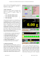
First screen of HMI after power-on, Fig. 4, gives us
results software integrity test and results of hardware
tests of integrated units. Fig.5 shows main operating
screen. Only product related data are shown.
Operating screen with detailed information of
weights on each hopper, vibrating intensities for RF
3.3 Master Application Software
ISSN: 1790-5117
224
ISBN: 978-960-474-064-2
Proceedings of the 10th WSEAS International Conference on AUTOMATION & INFORMATION
and CF, and mean weight supplied by each head is
presented in Fig.6. Additional information is
displayed for testing purpose.
3.4 Bus Transactions
Activity in bus has two modes of operation. First,
default one, is organized in cyclic fashion. Time
frame is divides by following sequence of
transactions:
1 - Slave1 Read/Write Multiple registers
2 - Slave2 Read/Write Multiple registers
{ 3 - Slave3 Read/Write Multiple registers
{ 4 - Slave1 any request
{ 5 - Slave2 any request
}
}
}
Fig. 4 Entrance screen with diagnostic results
Time period of one frame is 0.1 s. Transactions 1 and
2, at beginning of frame, are transaction for real-time
communication. They use function code 23 for
writing and reading in same cycle. Transaction 3 to
Slave3 (VFD) currently was used only for manual
speed set. Transactions 4 and 5 are used for acyclic
real-time communications or for non real-time
communications, with priority to acyclic real-time.
Second mode of bus activity is based on shorter
asynchronous transactions. Requests are divided in
two classes of high and low priority level [21].
Master sends cyclically general request to slaves and
slave sends data with highest priority.
Sequence of transactions for one pack cycle is:
Fig. 5 Main operating screen
1 - Set Time/Intensity for Circular Feeder and start
2 - Set Time/Intensity for Radial Feeder and start
3 - Release product from HH to WH
4 - Get weight data from Slave1 and display it
5 - Inform Slave2 for weight ready on WH
6 - Release product from WH to MH
7 - Best combination is sent to Slave2
8 - Release selected combination
9 - Inform packing machine and wait for request
10 - Request arrived and product is released
4. Initial Test Results
Fig. 6 Operating screen with weight state of each head
After all functions were implemented, system was
tested in open-loop. Range of control values for CF
and RF was found. Steady state characteristic for
potato chips speed of travelling as function of RF
intensity were constructed. And relation is in
agreement with results in [22] for bulk transport on
vibratory feeder. Offset type difference between RF
was observed. Using intensity of RF as e control
variable was not effective. Time of operation was
chosen as control variable for RF with intensity set
to some optimal value. Number of MH for discharge
was set to 3, as advised in [14]. With 75g and 175g
packs of potato chips system worked almost without
any adjustment. With smaller weights, 45g and 25g,
stopped conditions increased and were quite frequent
during 25g packing. It was observed that cycle time
of RF and not working time of RF is important
ISSN: 1790-5117
225
ISBN: 978-960-474-064-2
Proceedings of the 10th WSEAS International Conference on AUTOMATION & INFORMATION
References:
[1] http://www.anritsu.co.jp/E/Industry/
[2] http://www.ishidajapan.com
[3] http://www.simionato.com
[4] Katsuaki Kono, Combinatorial Weighing
Method and Apparatus, U.S. PATENT
4,549,618, 1985
[5] Katsuaki Kono, Weighing and Packaging
System, U.S. PATENT 6,401,437 B1, 2002
[6] Emilia Villani, Paula Eigi Miyagi, Robert
Valette, Modelling and Analysis of Hybrid
Supervisory Systems: A Petri Net Approach,
Springer, 2007
[7] John B. Weber, Applying Visual Basic for
Human Machine Interface Applications,
Instrument Society of America, 1999
[8] MODBUS over Serial Line Specification and
Implementation gide V1.0, Modbus.org, 2002
[9] MODBUS Application Protocol Specification
V1.1, Modbus.org, 2002
[10] Steve Mackay, Edwin Wright, John Park, Dean
Reynders, Practical Industrial Data Networks:
Design, Installation and Troubleshooting,
Newnes, 2003
[11] CFW-09 Frequency Inverter User's Guide,
WEG, 2008
[12] Paul Umbanhowar, Kevin M. Lynch, Optimal
Vibratory
Stick-Slip
Transport,
IEEE
Transaction on Automation Science and
Engineering, IEEE, 2008
[13] Tomoharu DOI, et.al, Feedback Control for
Electromagnetic Vibration Feeder, JSME
International Journal, Series C, Vol.44, No.1,
2001, pp. 44-52
[14] User Manual: Automatic Combination Weigher
K723A, Anritsu, 1987
[15] Alan R. Miller, 8080/Z80 Assembly Language:
Techniques for Impruved Programming, John
Wiley & Sons, 1981
[16] Modicon Modbus Protocol Reference Guide,
PI-MBUS-300 Rev. J,
[17] Steven T. Karris, Introduction to Stateflow with
Applications, Orchard Publications, 2007
[18] Stateflow and Stateflow Coder User's Guide,
The Mathworks, 2008
[19] http://ccrp.mvps.org/
[20] www.thescarms.com/download/CommIO.zip
[21] International Standard IEC 60870-5-103:
Transmission protocols - Companion standard
for the informative interface of protection
equipment, IEC, 1997
[22] Hamid El hor, et.al, Model for transport of
granular matter on vibratory conveyors,
Powders and Grains, 2005
control parameter. Closed-loop algorithms are being
tested. Initial test results for closed-loop control
could reach continuous speed up to 57 packs/second
for 25g packs. Same speed was reached when two
opposite heads were switched-off. This suggests that
speed limit is caused by volume of incoming
product. Controlling variance and mean value for
this multi-input multi-output system gave promising
results.
5. Conclusion
Combinatorial weighers are in production lines that
involve weighing with narrow tolerance is common
and irreplaceable. Of importance is its operation
without
human
intervention.
Function
of
combinatorial weighing includes two processes:
process of vibratory conveying and of combinatorial
selection of best candidate from number of choices.
To have the possibility of studying this process and
test different control strategies experimental setup
was created. For flexibility of implementation and
for testing different control strategies, control over
network communicating units is selected. Visual
Basic with its open architecture and with built in
functionality for user interface design is easily used
for creating HMI applications. This was shown by
designing this application down to the protocol
implementation. Experimental setup has proved
flexibility of MODBUS for implementing different
modes of activity in bus and ability to handle realtime control for slow processes. Ability of personal
computer (PC) of moderate performance to handle
HMI, low level protocol functionality and real time
control loops, including combinatorial calculation
without any dedicated hardware, is proved. To
enable flexibility of control, set of software functions
were implemented on slave side. Open-loop tests for
weighing product on real production line of potato
chips were done. In closed-loop control continuous
speed up to 57 packs/second for 25g packs could be
reached. Variance and mean value control loops
were used during closed-loop tests.
Initial tests have shown flexibility of setup in
implementing real-time closed-loop control over
MODBUS communication channel for combinatorial
weigher at potato chips production line.
Acknowledgement
Authors are grateful to Pestova Company for their
financial support, and for giving us free access to
their potato chips (Vipa Chips) production line for
performing on-line tests.
ISSN: 1790-5117
226
ISBN: 978-960-474-064-2