1
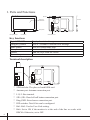
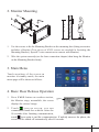
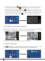
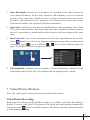
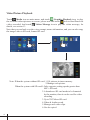
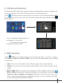
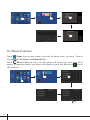
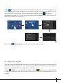
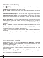
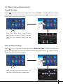
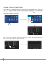
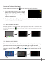
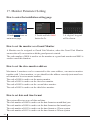
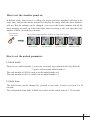
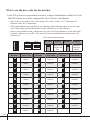
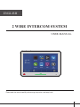
ENGLISH 2 WIRE INTERCOM SYSTEM USER MANUAL Please read this manual carefully before using the product, and keep it well. -1- 1. Parts and Functions Speaker Digital TFT LCD Screen DIP ON 123456 L1 L2 Antenna GND RING SWSW+ Microphone Emergency Button Connection Port Home Button Key functions Digital TFT LCD screen Emergency button Home button Microphone Speaker Connection port Display the visitors' image Press it 3 seconds to send the SOS message Press it to return home page Receive voice from the user Send out vioce from the visitor Bus terminal Terminal description SIM card slot DIP 123456 GND RING SWSW+ ON 123456 ON DIP L1 L1 L2 L2 Antenna port GND RING SWSW+ ** SIM card slot: The place to Install SIM card. ** Antenna port: Antenna connection port. ** L1,L2: Bus terminal. ** SW+,SW-: Door bell call button connection port. ** Ring,GND: Extra buzzer connection port. ** DIP switches: Total 6 bits can be configured. ** Bit1~Bit5: Used to User Code setting. -2- ** Bit6: Set to ON if the monitor is at the end of the line or works with DBC4A. Otherwise, set to OFF. 145~160 cm 2. Monitor Mounting 1. Use the screws to fix the Mounting Bracket on the mounting box.(fitting accesories includes a Bracket (Two pieces of 4X25 screws are needed for fastening the Mounting Bracket), Special 2 wire connectors to connect with Monitor) 2. Wire the system correctly(see the later connection chapter) then hang the Monitor on the Mounting Bracket firmly. 3. Main Menu Touch anywhere of the screen on monitor in standby mode, the main menu page will be shown as follows: 4. Basic Door Release Operation 1. Press CALL button on outdoor station, the Monitor rings, meanwhile, the screen displays the visitors' image. It will display the call source string 00:30 Front Door 2. To u c h icon on screen, you can communicate hands free with the visitor for 90 seconds.After finishing communication, touch icon again to end the communication. If nobody answers the phone, the screen will be turned off automatically after 40 seconds. -3- 3. 1. During talking state, touch icon to open the door for the visitor.(if two locks are connected to door camera, touch unlock 2nd icon to release the second lock ) 4. 2. When the monitor is in standby mode, touch Monitor icon on main menu to get into the door camera switching mode, if multi door stations are installed, you can select the door station or CCTV camera you want to monitor, and then the screen can display the view of outside. Press icon to exit and enter main menu page. Monitor Select DS-1 DS-2 DS-3 DS-4 CAM-1 CAM-2 5. Pan Tilt & Zoom In/Out Function During talking or monitoring state, you can zoom in or zoom out the range of monitoring to identify everyone at the entrance. Pan tilt to see individuals up close. Note that this function requires FishEye of door station support. 6. Intercom Function Touch Intercom icon on main menu to get into the intercom mode , you have 4 item to select:Inner Broadcast, Inner Call, Name List Call and Call Guard Unit. Inner Broadcast -4- Inner Call Name List Call Call Guard Unit 1. Inner Broadcast: If multi slave monitors are installed in the same apartment, select Inner Broadcast, all the other monitors will mandatory receive broadcast content at the same time, whichever slave monitors doesn't need to answer the broadcast, and whichever slave monitors also doesn't need to open the scrccn. Note that this mode is not supported call between monitors. 2. Inner Call: If multi slave monitors are installed in the same apartment, select Inner Call, all the other Monitors will ring at the same time, whichever Monitor answers the call, conversation is started.and the other monitors will stop ringing at the same time. 3. Name List Call: User in one apartment can call other apartments in the system. Touch Name List Call icon on intercom mode menu page, Select a name on the screen then touch icon to call.Press / icon to enter last/next name list page. (Touch Dial Number icon again to redial) Name List Inner Broadcast Inner Call Name List Call Call Guard Unit [01] [02] [03] [04] [05] [06] Abel Baron Ben Carl Dylan Charles 1. 4. Call Guard Unit: A Monitor can be assigned as Guard Unit Monitor; when the Guard Unit Monitor answers the call, conversation with the guard person is started.. 7. Video/Picture Memory Note: The video/picture memory function is built into the monitor. Video/Picture Recording Both Auto-Recording and Manual-Recording are available. And Auto-Recording is default. If receive a call after 3s, the monitor will record one video/picture automatically. Or you can touch icon to record the visitor's video/image manually when the monitor is in monitoring or calling. -5- Video/Picture Playback Touch Media icon on main menu, and touch Graphics Playback icon to play the recorded videos/pictures on screen, please note that touch icon to Start/Pause the videos recorded. And touch Visitor Message icon to play the visitor message, for details, see section 13. Note that you can look over the voice prompt, memo information, and you can also copy the image/video to SD card, format SD card. Graphics Playback Voice Prompt Copy To SD Format SD Card 00:03 Video:008/020 Visitor Message Memo Information 00:09 2015/06/23 14:36:55 Note: When the system without SD card: 1.118 pictures in inner memory 2.Manage each picture. When the system with SD card:1.Only supports writing speeds greater than 4M / s SD card. 2.A brand new SD card needs to be formated by the monitor, then it can be used for video recording. 3.Up to 32G Micro SD card. 4.Video & Audio record. 5.Manage each video clips. 6.Can be copied. -6- 8. Call Record Function Call Record:All the calls concerning the montior, including Door-station-to-monitor call, monitor-to-monitor call, will be recored and can be reviewed afterwards. Touch Call Record icon on main menu to get into the call record mode.When there are unread call records, arrow color red. Press the unread call record, and then touch icon to play it. Call Record Note: 1.Automatic limited number of records(max. 100 records). 2.System will automatically deleted exceed the records. 01/05 06-23 15:22 Calo.Liu 06-18 20:54 Smith 06-12 11:06 Vincent.Yang 05-29 08:39 Allen.Chen 05-27 21:43 Hebe.Zhang 04-20 13:16 Ben.Wu Call Record 01/05 06-23 15:22 Calo.Liu 06-18 20:54 Smith 06-12 11:06 Vincent.Yang 05-29 08:39 Allen.Chen 05-27 21:43 Hebe.Zhang 04-20 13:16 Ben.Wu 9. SMS Function Touch SMS icon on main menu to get into the sms mode , you have 3 item to select:Inbox, Outbox and Write a SMS. You can select the appropriate item according to your needs. 1. Inbox: You can view the inbox received the messages sent by other monitors. 2. Outbox: You can view the messages by this monitor sent to other monitors in the outbox. 3. Write a SMS: When you want to sent messages to other monitors, please touch Write a SMS icon enter the select receiver page, you can choose a item including Name List, Divert Numbers and Keypad at the page. After select the receiver you want, it will enter the editor page, input the messages you want, and then touch 'OK' to send. The steps will be shown as follows: -7- Select Receiver Inbox Outbox Name List Write a SMS Divert Numbers Keypad [ 00 ] abc _ Select Receiver [00] [01] [02] [03] [04] [05] 10. Phone Function Touch Phone icon on main menu to get into the phone mode, you have 3 item to select:Phone Call, Divert and Phone Device. Select Phone Call icon to get into the phone call mode page, select the divert number or input the number you want on the digital keypad, and then touch icon to call the phone. Divert Numbers Phone Call Divert Phone Device Tel 1:020-38629088 Tel 2:158xxxxxxxx Tel 3:137xxxxxxxx Divert Numbers -8- 020-38629088 Calling Divert Numbers Tel 1:020-38629088 Tel 1:020-38629088 Tel 2:158xxxxxxxx Tel 2:158xxxxxxxx Tel 3:137xxxxxxxx Tel 3:137xxxxxxxx 020-38629088 Select Divert icon to get into the divert numbers mode page, touch the empty item, it will enter the editor page,and input the telephone number by pressing the digital keypad, then touch 'OK' return divert numbers mode page, and then touch icon to save. Note that the system has 2 types of divert modes:Divert-Simutaneously and Divert-If No Answer, for details, see section 12. Divert Numbers Phone Call Divert Tel 1: Phone Device Tel 2: Tel 3: Inform Divert Phone Divert Numbers TEL NUMBER 1 123 3825XXXX_ Tel 1:3825XXXX Tel 2: Tel 3: Inform Divert Phone Note: Touch Phone Device icon to detect the divert device info. 11. Staircase Light Note: the staircase light function will be activated only when the system connect light via SC6V/RLC module, otherwise, this function is unvalid in normal. For more information, please refer to SC6V/RLC user instruction in detail. Touch Light icon on main menu page(or touch icon in monitoring/talking) to open the staircase light, the staircase light will be turned off automatically after 60 seconds. -9- 12. Call Scenario Setting Touch Call Scenario icon on main menu to get into the call scenario mode, you have 6 item to select: Normal: If you select this mode, the monitor as usual. Do Not Disturb: If you select this mode, outdoor station and other monitors can not call the monitor. Leave a Message, Immediately: If you select this mode, when the calls from outdoor station, The system will prompt visitors to leave a voice message, Immediately. Leave a Message, If No Answer: If you select this mode, Outdoor station calls indoor monitor firstly, if nobody answer the call within 30 seconds, the system will prompt visitors to leave a voice message. Divert, Simultaneously: Calls from outdoor station will be diverted to your telephone immediately.At this mode,the monitor won't shut off when TPC/GSM/TPS divert sucessfully, but if the monitor answers the call at this time,TPC/GSM/TPS will quit absolutely. Divert, If No Answer: Calls form outdoor station without respond in 30 seconds will be transfer to the number you set. Even though the monitor will shut off when transfer via TPC/GSM/TPS, you still available to operate it (such as monitor, talk, and unlock). * Note: The call scenarios setting are the response mode of monitor when outdoor station call. Some of the advanced features if not inserted SD card does not fully used, such as voice message function. 13. Auto Message Function When you leave home, you can select Leave a Message, Immediately or Leave a Message, If No Answer in the call scenario page, if receive a call, the monitor can leave a voice message automatically. If you selecte Leave a Message, Immediately: Press CALL button on outdoor station, you can hear the message prompt immediately, and then leave a message you want within 10 seconds. If you selecte Leave a Message, If No Answer: Press CALL button on outdoor station, if nobody answer the call within 30 seconds, you can hear the message prompt, and then leave a message you want within 10 seconds. -10- 14. Basic Setup Instructions Sounds Settings Touch icon on main menu page, then select "Sounds" item to enter the sounds settings page.You can set a variety of ring tones on this page.(touch icon to exit the setting and return main menu page. Note: Door Ring have 2 mode:United and Separate. If select "United",it means Door1/2/3/4 as a unity to adjust the ring tones. 01 Popular Ring Tone Door1 Door2 Door3 Door4 Intercom Bell Alert 01 03 04 01 01 01 Volume 02 Door Ring Mode Day 06 United Night 03 Separate Date & Time Settings Touch icon on main menu page, then select "Date & Time" item to enter the date & time settings page.You can set the date & time on this page.(touch icon to exit the setting and return main menu page. Note: You can set your own time, you can also synchronize the system time. Date&Time 2015 08 01 02 35 30 Sync Sync From System Clock -11- Rename & Monitor Time Settings Touch icon on main menu page(or on door camera switching mode page), then select "More..." item to enter the Rename & monitor time settings page. You can rename door station and camera, change monitor time on this page.(touch icon to exit the setting and return main menu page) Door Station Rename Camera Rename DS-1 CM-1 DS-2 CM-2 DS-3 CM-3 DS-4 CM-4 Monitor Time Set 30 sec Note: If you want to rename, please touch the place of name, then it will turn keypad page ,you can input your new name in this page. Door Station Rename CM-1 DS-2 CM-2 DS-3 CM-3 DS-4 CM-4 Monitor Time Set 30 sec -12- Camera Rename DS-1 DOOR3 RENAME DS-3_ abc Screen and Volume Adjustment During monitoring or talking, touch icon, the Adjust icon will be displayed. 1. The Scene mode selection: Total 4 screen modes can be selected in sequence: Normal, Brightly, Soft and User. Whenever you modify Brightness or colour, Scene item will be set to User mode automatically. 2. Note that all the adjust will be performed immediately after the operation. Touch the window of image to exit the adjust page. 15. SOS SMS Function When the monitor is in standby mode, press Emergency button for 3 seconds to enter the SOS SMS page, touch icon, it will sent "Help" to the divert number you set(see section 10). Send SOS SMS ? SMS Sent Out ! 16. Restore to Default The restore to default function allows the user to recover the settings to factory setting. Note that the restore to default operation will not change the all setting and datas. Enter main menu page, touch icon, then select "About" item (or touch logo position) to enter the about settings page, touch icon, the default settings will be loaded. About Local Address 00.00 Video Standard AUTO System Verson 00.01.00 Display Driver 1.0 Font 1.0 UI 1.0 Restore To Default ? -13- 17. Monitor Parameter Setting How to enter the installation setting page INSTALLER SETUP About 1.Touch icon on main menu page. 123 _ Local Address 00.00 Video Standard AUTO System Verson 00.01.00 Display Driver 1.0 Front 1.0 UI 1.0 2.Touch and hold 'SOS' button for 2s. 3.A digital keypad will be shown. How to set the monitor as a Guard Monitor A Monitor can be assigned as Guard Unit Monitor; when the Guard Unit Monitor answers the call, conversation with the guard person is started.. The code number of 8004 is used to set the monitor as a guard unit monitor and 8005 is used to cancel this function. How to set the slave monitor address Maximum 4 monitors can be connected in the same address, one master monitor together with 3 slave monitors, so you should set the address correctly.(note:must have one monitor to be set as master monitor) The code of 8000 is used to set the master monitor. The code of 8001 is used to set the first slave monitor . The code of 8002 is used to set the second slave monitor . The code of 8003 is used to set the third slave monitor . How to set date and time format The system offers two ways of date and time. The code number of 8008 is used to set the date format as month/date/year The code number of 8009 is used to set the date format as date/month/year The code number of 8012 is used to set the time format as 12 hour system The code number of 8013 is used to set the time format as 24 hour system -14- How to set the monitor panel on In default mode, when receive a calling, the master and slave monitors will ring at the same time, and just the master monitor can display the image while the slave monitors will not. But the settings can be changed, you can set the master monitor and all the slave monitors to panel on at the same time when receiving a call, just input the code number of 8006 on each slave monitor. How to set the unlock parameter Unlock mode: There are two unlock modes: 1.power-on- to-unlock type:unlock mode=0(by default) 2.power-off-to-unlock:unlock mode=1. The code number of 8010 is used to set the unlock mode to 0 The code number of 8011 is used to set the unlock mode to 1 Unlock time: The unlock time can be changed by yourself at any time. it can be set from 1 to 99 seconds. The code number from 8401 to 8499 are used to set the unlock time to 1~ 99 seconds. -15- How to set the user code for the monitor In the DT system,every apartment must have a unique identification called User Code. The DIP swiches are used to configure the User Code for each Monitor. Bit-6 is line terminal switch, which have to be set to ON if the Monitor is in the end of the line(bus), otherwise set to OFF. The end of the line is terminal that no other section will start from it. Bit-6 line terminal setting: DIP ON 123456 ON DIP ON DIP 123456 ON DIP 123456 ON DIP Code=25 Code=26 123456 ON DIP Code=24 Code=27 123456 ON DIP User Code Code=28 123456 ON Code=22 Monitor at the end of the line. Code=23 Code=29 123456 DIP ON Code=21 DIP ON Code=20 DIP ON Code=19 Setting 123456 Bit state 123456 Code=18 DIP Monitor not at the end of the line. 123456 Bit state 123456 DIP DIP 123456 ON DIP ON DIP 123456 ON DIP 123456 ON DIP 123456 ON DIP 123456 ON DIP 123456 ON Code=15 Code=17 123456 DIP DIP Code=14 Code=16 123456 ON Code=11 DIP ON Code=10 DIP ON Code=9 Code=13 123456 Code=8 Code=12 123456 Code=7 Setting User Code 123456 Bit state 123456 Bit state OFF(0) ON DIP 123456 ON DIP ON DIP 123456 ON DIP 123456 ON DIP 123456 ON DIP 123456 ON DIP 123456 ON DIP Code=4 Code=6 123456 ON DIP Code=3 Code=5 123456 ON DIP Code=2 123456 ON DIP Code=1 123456 ON User Code 123456 Bit state -16- ON(1) ON ON 123456 DIP • ON • Bit-1 to Bit-5 are used to User Code setting. The value is from 1 to 32, which have 32 different codes for 32 apartments. When multi Monitors are installed in one apartment, these Monitors have to use the same User Code setting, and the Master/Slave mode should be set on the Monitor. ON • Code=30 Code=31 Code=32 18. Specification ●● Power supply: DC 20~28V ●● Power consumption: Standby 20.9mA; Working 350mA ●● Monitor screen: 10 Inch digital color TFT ●● Display Resolutions: 800*3(R, G, B) x 480 pixels ●● Video signal: 1Vp-p, 75Ω, CCIR standard ●● Wiring: 2 wires, non-polarity ●● Dimension: 178(H)×268(W)×24(D)mm DT-ENG-31M/GSM/TD10-V1 The design and specifications can be changed without notice to the user. Right to interpret and copyright of this manual are preserved.