1
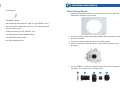
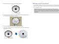
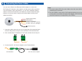
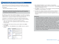
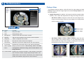
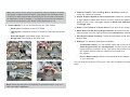
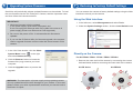
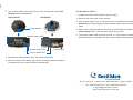
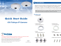
1
Introduction
Welcome to the GV-Fisheye IP Camera Quick Start Guide. In the following
sections, you will learn the basic installations and configurations of
GV-Fisheye IP Camera. For the detailed user manual, see the GV-Fisheye
IP Camera User Manual on the GV-Fisheye IP Camera Software DVD.
Note: GV-FE110 / FE111 / FE420 / FE421 / FE520 / FE521 are for indoor
use, while GV-FER521 is designed for outdoor environment.
Packing List
• Camera Body
Quick Start Guide
GV-Fisheye IP Camera
Note:
1. GV-FE110 / FE420 / FE520 are excluded from Japan, EU and German market.
2. No memory card slot or local storage function for Argentina.
Thank you for purchasing GV-Fisheye IP Camera. This guide is designed to
assist the new user in getting immediate results from the GV-Fisheye IP
Camera. For advanced information on how to use the GV-Fisheye IP Camera,
please refer to GV-Fisheye IP Camera User's Manual on Software DVD.
© 2012 GeoVision Inc. All rights reserved.
2012/08
English
FE111421521-QG-F
• Camera Cover
(Hard-Ceiling Mount)
• Camera Cover
(In-Ceiling Mount)
• Screw
(Hard Ceiling Mount) x 3
• Screw
(In-Ceiling Mount) x 3
• Support Bracket x 3
• Plastic Screw Anchor x 3
2
• Torx Wrench
Hardware Installation
Hard Ceiling Mount
1. Place the installation sticker on the ceiling board. The 3 red dots
indicate the location of the screws.
• Installation Sticker
• Silica Gel Bag and Adhesive Tape x 2 (GV-FER521 only)
• DC 12V Power Adaptor and 3-Pin or 2-Pin Terminal Block
(GV-FE series only)
• Cable Connector (for GV-FER521 only)
• GV-Fisheye IP Camera Software DVD
• GV-NVR Quick Start Guide
2. At the 3 red dots, drill a hole slightly smaller than the plastic screw
anchors provided.
• GV-NVR Software DVD
3. Insert the 3 plastic screw anchors in the drilled holes.
4. Secure the fisheye camera with the 3 hard ceiling mount screws
provided.
5. For GV-FER521, install the supplied cable connector to waterproof
the cable. You should have 5 components:
1
2
3
4
5
a. Prepare an internet cable with the RJ-45 connector on one end
only.
In-Ceiling Mount
In-Ceiling Mount allows the GV-Fisheye IP Camera to be mounted into
b. Connect the internet cable to the camera cable.
the ceiling, revealing a small portion of the camera. In-Ceiling Mount
c. Paste the sticker to the camera cable and slide in all the
requires the ceiling board to be between 0.5 – 3.0 cm (0.2 – 1.18 in).
components as shown below.
1. Place the installation sticker on the ceiling board, and cut the circle
part out of the ceiling.
d. Move all the components toward the RJ-45 connector, fit item 4 to
item 2, secure item 3 to the camera cable and finally secure item
5 to item 2 tightly.
2. Align the 3 support brackets with the holes on the back of the camera
and secure using the in-ceiling mount screws provided.
IMPORTANT: Item 5 must be secured tightly to waterproof the cable.
6. Place the camera cover for hard ceiling mount on top of the camera
and tighten the screws with the torx wrench provided.
3. For GV-FER521, install the supplied cable connector to waterproof
the cable. Refer to step 5 in Hard Ceiling Mount for details.
4. Place the fisheye camera into the ceiling opening.
Wall Mount and Ground Mount
To mount the camera on a wall, follow the instructions in Hard Ceiling
Mount. For ground mount, simply place the camera on a flat surface such
as a conference table.
Hint: Mount the fisheye camera in the middle of the wall to have an
excellent overview. Or ensure the camera is focused on the most important
areas of the room as directly as possible to have the desired detailed
recognition.
5. On the back side, make sure the black plastic clips are slightly above
the ceiling board and pointing outward.
6. From the front side of the camera, tighten the screws.
7. Place the camera cover for in-ceiling mount on top of the camera and
tighten the 3 screws.
3
Connecting the Power Cables
You can use a Power over Ethernet (PoE) adaptor to connect the
GV-Fisheye IP Camera on the network, and the power will be provided
over the network cable. Alternatively, you can use a standard network
cable to connect the camera to your network, and then follow the steps
below to connect to power using the 5-pin data cable and the power
adaptor provided.
Digital Output (Red)
GND (Black)
Digital Input (Brown)
AC 24V+ / DC 12V+ (Yellow)
AC 24V- / DC 12V- (Orange)
Ethernet (PoE)
1. Insert the yellow wire to the pin on the right-side of the terminal block
and the orange wire to the pin on the left-side of the terminal block.
2. Use a small flat-tip screwdriver to secure the screws above the pins.
3. Connect the DC 12V Power Adaptor to the Terminal Block.
Terminal Block
DC 12V Power Adaptor
Note:
1. The power status LED will not be visible unless the outer shell of the
camera body is removed.
2. The GV-FER521 comes with a PoE cable that allows you to connect
to the power and network through a PoE adaptor. Note that digital
input and output are not supported in GV-FER521.
4
Accessing the GV-Fisheye IP Camera
Once installed, your GV-Fisheye IP Camera is accessible on a network.
Make sure your PC has good network connection, and meet this system
requirement:
4. Select Static IP address. Type IP Address, Subnet Mask,
Router/Gateway, Primary DNS and Secondary DNS in the Configure
connection parameters section.
• Microsoft Internet Explorer 7.x or later
5. Click Apply. The camera is now accessible by entering the assigned
IP address on Internet Explorer 7.x or later.
Note: If you are using Microsoft Internet Explorer 8.0, additional settings
are required. Please refer to Settings for Internet Explorer 8, Appendix A,
GV-Fisheye IP Camera User Manual.
By default, the camera has a default IP address of 192.168.0.10. However,
when GV-FE420 / 421 / 520 / 521 or GV-FER521 connects to the LAN with
a DHCP server, a dynamic IP address will be assigned instead of
192.168.0.10. If no DHCP server exists, the default IP address will be
applied and you can follow the steps below to assign a static IP address.
6. To enable the updating of images in Microsoft Internet Explorer, you
must set your browser to allow ActiveX Controls and perform a
one-time installation of GeoVision’s ActiveX component onto your
computer.
IMPORTANT:
•
If Dynamic IP Address or PPPoE is enabled, you need to know which
IP address the camera will get from the DHCP server or ISP to log in. If
your camera in installed in a LAN, use the GV-IP Device Utility to look
up its current dynamic IP address. See Checking the Dynamic IP
Address, Chapter 2, GV-Fisheye IP Camera User's Manual.
If your camera uses a public dynamic IP address via PPPoE, use the
Dynamic DNS service to obtain a domain name linked to the camera’s
changing IP address first. For dynamic DNS server settings, see
Advanced TCP/IP, Chapter 4, GV-Fisheye IP Camera User's Manual.
•
If Dynamic IP Address or PPPoE is enabled and you cannot access
the camera, you may have to reset it to the factory default settings and
then perform the network settings again. Refer to section 7 to see how
to restore to factory default settings.
1. Open your web browser, and type the default IP address:
http://192.168.0.10. The computer must be under the same network
as the camera.
2. In both Login and Password fields, type the default value admin.
Click Apply.
3. In the left menu, select Network and then LAN to begin the network
settings.
Continued on the reverse
5
The Web Interface
Fisheye View
10
9
8
To enable the fisheye options, right-click the live view image and select Geo
Fisheye. Right-click the image again and select Fisheye Option to see the
following options.
● Image Alignment: By default, the image should be properly aligned
already. If not, follow the steps below to align the image for each model:
•
1 2 3 4
GV-FE110 / FE111: Align the circle with the outer edge of the camera
image, and then align it with the inner edge of the image frame to
achieve optimal results.
5 6 7
No. Name
Function
1
Play
Plays live video.
2
Stop
Stops playing video.
3
Microphone
Listens to the audio around the camera.
4
Speaker
Talks to the surveillance area from the local computer.
5
Snapshot
Takes a snapshot of live video.
6
File Save
Records live video to the local computer.
7
Full Screen
Switches to full screen. Right-click to see more options.
8.
I/O Control
Enables the I/O Control Panel or the Visual Automation.
9.
Show System
Brings up these functions: Alarm Notify, Video and Audio
Menu
Configuration, Remote Config, Show Camera Name and
Outer edge
Inner edge
•
GV-FE420 / FE421 / FE520 / FE521 / FER521: Align the red circle
with the edge of the camera image. You can eliminate the darker
areas toward the edge of the image by making the red circle smaller,
but the field of view will be slightly reduced.
Image Enhance.
10. Control Panel
Displays the camera information, video settings, audio data
rate, I/O device status, images captured upon alarm, and
GPS location of the camera. Also allows you to adjust image
quality and install the program from the hard drive.
GV-FE420 / FE421
GV-FE520 / FE521 / GV-FER521
Note: The circular source image of GV-FE420 / FE421 should be centered
and slightly cropped on all four edges. If the image is not centered, please
contact your sales representative and send your device back to GeoVision
for adjustment. Refer to Chapter 3, GV-Fisheye IP Camera User's Manual
to see how to determine if your device needs adjustment or not.
● Camera Modes: You can choose among four view modes.
•
Quad view: Composed of four PTZ views.
•
360 degree: Composed of two PTZ views and one 360º panoramic
view.
•
Dual 180 degree: Composed of two 180º views.
•
Single view: Composed of one PTZ view.
● Camera Position: Select Ceiling, Wall or Ground according to
where the camera is mounted.
● Adjust AutoPan Speed At Top-Left Channel: Select low, medium,
or high speed to enable Auto Pan for one PTZ view at the rotation
speed of your choice. This option applies to Quad view, 360 degree
and Single view.
● Zoom: Select Zoom In or Zoom Out and then click on the image.
● Show Source Video At Top-Right Channel: Shows the circular
source image in the top-right quadrant when Quad view is selected.
● 360 degrees Object Tracking: Tracks moving objects under 360
degree view.
● Settings: The following settings are available.
Quad view: 4 PTZ views
360 degree: 2 PTZ & 1 360º views
•
Frame Rate Control: You can set the frame rate of the live view.
•
Show Original Video in Low Resolution: Shows circular source
image when the resolution is low. This option only works on the
GV-System when the fisheye camera is connected to a
GV-System.
•
Screen Ratio Setting: Select a ratio that best fits the display ratio
of your computer.
You can drag and drop the PTZ view or 180º view to adjust the viewing
angle.
Dual 180 degree: 2 180º views
Single view: 1 PTZ view
Note: When the wall mount is selected for Camera Position, only one
180º view will be displayed.
6
Upgrading System Firmware
GeoVision will periodically release updated firmware on the website. To load
the new firmware into the GV-Fisheye IP Camera, read the important notes
and then follow the instructions below.
7
Restoring to Factory Default Settings
You can restore the camera to factory default settings using the Web
interface or directly on the camera.
Using the Web Interface:
IMPORTANT:
1 While the firmware is being updated,
A. the power supply must not be interrupted, and
B. do not unplug the Ethernet cable if the cable is the source of
power supply (Power over Ethernet or PoE supported).
1. In the left menu, select Management and select Tools.
2. Under the System Settings section, click the Load Default button.
2. Do not turn the power off for 10 minutes after the firmware is
updated.
3. If you use the IP Device Utility for firmware upgrade, the computer
used to upgrade firmware must be under the same network of the
camera.
1. In the Live View window, click the Show
System Menu button
on the right
and select Remote Config.
2. Click the Browser button to locate the
firmware file (.img) saved at your local
computer.
3. Click the Upgrade button to process the
upgrade.
WARNING: The interruption of power supply during updating causes
not only update failures but also damages to your camera. In this case,
please contact your sales representative and send your device back to
GeoVision for repair.
Directly on the Camera:
For GV-FE420 / FE421 / FE520 / FE521 / FER521:
1. Remove the outer shell of the camera by unscrewing the screws
indicated below and then removing the outer shell of the camera.
GV-FE Series
GV-FER521
2. Use a pointy object such as the tip of a pen to hold down the Load
default button labeled below.
GV-FE Series
GV-FER521
1. Unplug the power cable and the network cable.
2. Remove the outer shell of the camera.
3. Use a pointy object such as the tip of a pen to hold down the Load
default button while plugging back the power cable and the network
cable.
Load default
4. Wait until the network status LED turns off momentarily to release the
Load default button. This may take about 40 seconds.
5. The system status LED should turn back on. The process of loading
default settings is completed and the camera reboots automatically.
Network status LED
System status LED
For GV-FE110 / FE111:
Load default
Power status LED
3. Release the default button when the status LED blinks.
4. When the status LED fades, the process of loading default settings is
completed and the camera reboots automatically.
9F, No. 246, Sec. 1, Neihu Rd., Neihu District, Taipei, Taiwan
Tel: +886-2-8797-8376 Fax: +886-2-8797-8335
[email protected]
http://www.geovision.com.tw