1
2004-2-4
LX-5000 series 02 type
LX-5600 2-sheet dot matrix printer
LX-5700 2-sheet thermal printer
LX-5750 1-sheet thermal printer
Interfaces & /
Peripherals /
Manual
/"
CAUTION!
When the control key position is LOCK, the display is
off and keyboard is disabled but the ECR's power is still
ON. So that before you connect the cable of
peripherals, make sure that the AC cord is disconnected
otherwise the ECR will be damaged.
CONTENTS
I. INTERFACE INFORMATION ......................................................................................... 1
II. IRC SYSTEM ..................................................................................................................... 4
III. PERIPHERALS................................................................................................................. 6
1. TERMINAL PRINTERS........................................................................................................... 6
1)
2)
3)
4)
TP-822/832 (Kitchen Printer, connected to ch-A)....................................................................... 6
TP-620 (Slip Printer, connected to ch-A).................................................................................... 7
CBM-1000 (Thermal Kitchen Printer, connected to ch-A via NA-710/730) .............................. 8
TM-T88III (Thermal Slip Printer, connected to ch-B)................................................................ 9
2. SCANNER ................................................................................................................................ 10
3. SCALE ...................................................................................................................................... 12
1) Scale Information of ICL Protocol [SF-25.a=0].......................................................................... 13
2) Scale Information of W Protocol [SF-25.a=1] ............................................................................ 15
4. EFT TERMINALS................................................................................................................... 16
IV. PC COMMUNICATION ............................................................................................... 17
1. BATCH COMMUNICATION................................................................................................ 17
2. PROGRAM LOADER (PLM 2000) ....................................................................................... 17
3. ESF DATA TRANSFER (Electronic Store & Forward)...................................................... 18
V. ECR TO ECR RAM DATA TRANSFER ...................................................................... 20
VI. JOURNAL DATA TRANSFER .................................................................................... 21
VII. CABLE CONNECTION............................................................................................... 22
1. CHANNEL A --- IRC LINE.................................................................................................... 22
2. CHANNELS B, D & E ............................................................................................................. 24
1) ECR (ch-B) to Thermal Slip Printer TM-T88III ......................................................................... 24
2) ECR (ch-B, ch-D/E) to Scale....................................................................................................... 24
3) ECR (ch-B, ch-D/E) to PC .......................................................................................................... 24
4) ECR (ch-B, ch-D/E) to Handy Scanner ....................................................................................... 25
5) ECR (ch-B, ch-D/E) to Flat Bed Scanner .................................................................................... 25
6) ECR (ch-B, ch-D/E) to Peripheral for Journal Data Transfer...................................................... 26
7) ECR (ch-B) to ECR (ch-B) for RAM Data Transfer ................................................................... 26
8) ECR (ch-B) to EFT Terminal ....................................................................................................... 27
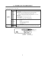
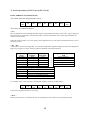
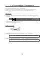
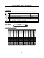
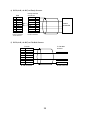
I. INTERFACE INFORMATION
The following interfaces are provided:
Channel
A RS485
Standard
Interface
B RS232C
(62100)
LX IF7-1 K-UNIT
(option)
D
RS232C
E
RS232C
Used for
IRC : up to 8 units including an ECR master or PC as IRC master (Tensai2000) via
NA-720
4 kitchen printer -- one of kitchen printer can be used as a slip printer
TP-822 : Citizen DP-416 impact dot matrix printer with auto cutter
TP-832 : Citizen LT-1320 thermal printer with auto cutter
CBM-1000 : thermal printer with auto cutter (connected via NA-710/730)
4 slip printers
TP-620 : Epson M290 impact dot matrix printer
Network Adapters
NA-710/730 for 1 or 3 thermal kitchen printer(s)
NA-720 for PC as IRC master or for Modem to PC
One of : - PC batch communication, Programming Loader Module PLM 2000
- Scanner
- Scale
- Thermal slip printer TM-T88III
- ECR to ECR RAM data transfer
- Journal data transfer
- EFT terminal
Same as channel B
(except Thermal slip printer TM-T88III, ECR to ECR RAM data transfer and EFT
terminal)
Channel C is not used.
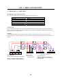
CH-E
CH-D
CH-B RS232C
9-pin D-sub
1
CH-D, E (option)
RS232C
9-pin D-sub x 2
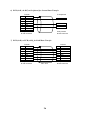
CH-A RS485
RJ-45 modular type
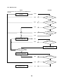
System Configuration
Maximum 8 units can be connected via IRC line including the master, max. 4 kitchen printers and
max. 4 slip printers. However, an ECR can use one slip printer.
PC as IRC master
(Tensai2000)
Slip printer, max. 4
TP-620
RS232C
MODEM
MODEM
NA-720
Kitchen printer, max. 4
TP-822/832
(direct connection to PC available)
NA-710
ECR as master
Thermal kitchen printer, max. 1
CBM-1000
RS232C
Thermal kitchen printer, max. 3
CBM-1000
NA-730
RS232C
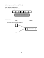
Standard Interface
Channel A : RS485
Channel B : RS232C
#62100 LX IF7-1 K-UNIT
(option)
Channel D : RS232C
Channel E : RS232C
Thermal slip printer TM-T88III
or
PC batch communication
PLM 2000
or
ECR to ECR RAM data transfer
or
EFT terminal
or
Handy scanner or
Flat-bed scanner
or
or
Scale
or
Journal data transfer (monitor, printer, etc.)
Same as channel B except:
- Thermal slip printer TM-T88III
- ECR to ECR RAM data transfer
- EFT terminal
2
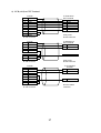
Pin Assignment & Character Structures
CHANNEL A
(RS485, RJ-45 modular type connector)
Baud rate :
19200 bps or 38400 bps [SF-89.a]
Character structure :
(fixed)
PIN #
1
2
3
4
5
6
7
8
start bit = 1 bit
data bit = 8 bits
stop bit = 2 bits
parity = even
CHANNEL B
(RS232C, 9-pin D-sub female connector)
Block size :
1024 characters for PC batch communication
Baud rate :
600 ~ 38400 bps [SF-94.f~h]
9600 ~ 38400 bps [SF-89.d,e] for ECR to
ECR RAM data transfer
Character structure :
start bit = 1 bit
data bit = 7 bits or 8 bits [SF-94.b]
stop bit = 1 bit or 2 bits [SF-94.d]
parity = odd, even or null [SF-94.a,c]
I/O
SIGNAL
DATA+
DATACTL+
N.C.
N.C.
CTLN.C.
N.C.
FUNCTION
Comm. data signal (+)
Comm. data signal (-)
Comm. line control (+)
FUNCTION
Protection ground
Transmitted data
Received data
Request to send
Clear to send
Power supply for handy
scanner (max. 200 mA)
Signal ground
Data carrier detect
Data terminal ready
PIN #
1
2
3
4
5
6
OUT
IN
OUT
IN
OUT
SIGNAL
P.GND
TXD
RXD
RTS
CTS
+5V
7
8
9
IN
OUT
GND
DCD
DTR
Comm. line control (-)
Optional interface board LX IF7-1 K-UNIT : Channels D and E (channel C is not used)
CHANNEL D
CHANNEL E
Same specification as channel B above.
System function [SF-98] for channel D and [SF-100] for channel E are used for the setting of baud rate and character
structure.
3
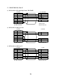
II. IRC SYSTEM
The master PC or ECR can transmit programming data to the slave ECRs and collect the sales data
from the slave ECRs via channel A.
!
!
PC as Master using PC-IRC communication module Tensai2000
ECR as Master : Any ECR can be a master ECR.
Preparation
Before using the IRC system, the following presetting must be performed:
a) For new machines being added to the system, perform RAM test SP-9901 to erase all RAM
contents. Do not perform this operation on the machines already used as it will erase all
preset data.
b) Confirm the following three points on each ECR:
1. Each ECR is connected by the IRC line. Refer to VII. Cable Connection (page 22).
2. ECR machine number (PGM-171)
The last two digits of the machine number used for ECR ID #, must be 01 ~ 08 and different for
each ECR.
3. Baud rate of all ECRs [SF-89.a] (PGM-100)
SF-89
1/0
bit
a
1
Baud rate: IRC line (ch-A) is 38400 bps
4
0
19200 bps
c) IRC status check operation
Either a PC as master or ECR as master, perform SP/X-8800 IRC STATUS CHECK on ECR as
follows:
< SP >--(8800)--[X2/ENTER]--[ • /ENTER] or select IRC PROGRAM and 8800 IRC STATUS CHECK from the list
< X >--(8800)--[X2/ENTER]--[ • /ENTER] or select IRC STATUS CHECK from the list
During SP/X-8800 IRC STATUS CHECK, the following message is displayed:
Master
Slave
BUSY
--- IRC COMM ---
ACCEPT-[ENT / .]
CANCEL - [ CL]
P
ECR#-01
P
The master ECR will check ECR sequential number up to 8, even when there are fewer ECRs than 8
ECRs on the IRC line.
After IRC status check is completed, all ECR's connected can communicate via IRC line, and the IRC
system configuration table is printed as follows:
S-8800
01 #101 OK
02 #102 OK
03 #103 OK
#101-000006
ECR sequential #, machine #, IRC status
19:07P
If there is a communication error, 'NG' will be printed instead of 'OK'. Retry SP/X-8800 operation.
For the "Program data transfer from master to slaves", "IRC report" and "IRC messages", please refer
to programming manual.
5
III. PERIPHERALS
1. TERMINAL PRINTERS
Refer to VII. Cable Connection (page 22).
Following printers are available.
Model
TP-822/832
CBM-1000
TP-620
TM-T88III
Used for
kitchen printer (dot/thermal)
kitchen printer (thermal)
slip printer
slip printer (thermal)
Connected to
channel A
channel A via NA-710/730
channel A
channel B
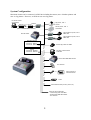
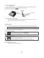
1) TP-822/832 (Kitchen Printer, connected to ch-A)
paper outlet
power switch
power LED
ECR SETTINGS
FEED switch
a) Program the following:
[SF-107.e~h]
kitchen printer to be used
[SF-108,109]
back-up kitchen printer
[SF-89.a]
baud rate for IRC line [1] 38400 bps, [0] 19200 bps
The character structure for IRC line has already been fixed on ECR.
(1 start bit, 8 data bits, 2 stop bits, even parity)
[PF-4.e~h]
PLU data to be transmitted to which kitchen printer
b) Program the ECR name and the kitchen printer name by the character programming (PGM-152). These
names are printed on the kitchen printer every time, like "ECR name --> KP name".
c) When the kitchen printer is used as a bill printer, select the following flags:
[SF-83.h]
[1] with slip printer
[SF-86.a,b]
[0,1] printer selection for bill : TP-822/832
[SF-87.a,b]
select one of the kitchen printers
If required, the upper logo and lower logo can be printed on the bill.
[SF-83.d]
upper logo printed on slip
[SF-85.a~d]
number of blank lines between the upper logo and the items
[SF-86.d]
lower logo printed on slip
[SF-86.e~h]
number of blank lines between the lower logo and the last item
TERMINAL PRINTER SETTINGS
Refer to TERMINAL PRINTER PROGRAMMER'S MANUAL.
6
2) TP-620 (Slip Printer, connected to ch-A)
form stopper release switch
Cancels the form stopper.
two-digit LED
RELEASE switch
Releases paper or starts / stops test printing.
PRINT switch
Feeds paper if buffer is empty or prints data which is in buffer.
FUNCTION switch
power switch
Back feeds paper.
ECR SETTINGS
a) Select following:
[SF-83.h]
[SF-89.a]
(PGM-179)
[1] with slip printer
baud rate for IRC line: [1] 38400 bps, [0] 19200 bps
The character structure for IRC line has already been fixed on ECR.
(1 start bit, 8 data bits, 2 stop bits, even parity)
Slip printer ID # (should match DIP SW 2 setting of TP-620)
b) See [SF-82 ~ 86] for other selections:
slip validation with logo, bill issue format, time print, slip logo, slip print compulsory condition,
automatic slip print, maximum item lines on slip, pre-feed lines on slip, etc.
TP-620 SETTINGS
Refer to the separate document "TERMINAL PRINTER TP-620 USER'S MANUAL".
7
3) CBM-1000 (Thermal Kitchen Printer, connected to ch-A via NA-710/730)
Before using, ECR original character must be installed by using CBM-1000-UW ROM.
ECR SETTINGS --- same settings as TP-822/832 (page 6)
NETWORK ADAPTER SETTINGS
NA-710 : 1 printer can be connected
NA-730 : up to 3 printers can be connected
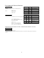
Unplug the cord and set the dip switches as shown below:
Plug the cord to fix the setting.
DIP SW
SW1 - 1, 2
SW1 - 3
SW2 - 1
SW2 - 2 ~ 4
SW3 - 1
SW3 - 2
SW3 - 3, 4
SW4 - 1, 2
SW4 - 3, 4
NA-710/730
[OFF,ON] 19200 bps for RS232C
Baud rate for RS485 (set the same baud rate as ECR [SF-89.a])
[ON] 38400 bps [OFF] 19200 bps
[OFF] printer ID # 1 ~ 4 (also set SW3, SW4)
[OFF,OFF,OFF] printer selection CBM-1000
[OFF] auto cut at text end
[ON] full cut [OFF] partial cut
NA-710 / CH-1 of NA-730
[SW2-1=OFF] → [OFF,OFF] ID# 1 [ON,OFF] ID# 2 [OFF,ON] ID# 3 [ON,ON] ID# 4
CH-2 of NA-730
[SW2-1=OFF] → [OFF,OFF] ID# 1 [ON,OFF] ID# 2 [OFF,ON] ID# 3 [ON,ON] ID# 4
CH-3 of NA-730
[SW2-1=OFF] → [OFF,OFF] ID# 1 [ON,OFF] ID# 2 [OFF,ON] ID# 3 [ON,ON] ID# 4
CBM-1000 SETTING
Turn off the printer power button and set the dip switches as shown below:
Turn on the power button to fix the setting.
DIP SW
DS 1 - 1
DS 1 - 2 ~ 4
DS 1 - 5
DS 1 - 6
DS 1 - 7, 8
DS 2 - 1 ~ 4
DS 2 - 5 ~ 8
DS 3 - 1 ~ 4
DS 4 - 1 ~ 4
ON
OFF,OFF,OFF,OFF
ON
OFF
ON,OFF
all OFF
all OFF
OFF,ON,ON,OFF
ON,ON,OFF,OFF
CBM-1000
with auto cutter
print mode: high-speed, paper width: 80 mm, print columns: 48
CR mode: LF operation
input buffer: 4K bytes
print density : standard
ECR original character set
JIS, condition for busy to occur: off-line and reception buffer full
8-bit data, even parity, DTR/DSR control
19200 bps (RS232C)
8
4) TM-T88III (Thermal Slip Printer, connected to ch-B)
Before using, ECR original character must be installed standard by using TM-T88III-UW(s) ROM.
Communication setting of ECR for TM-T88III has been fixed to: 19200 bps, even parity, 8-bit data, 2
stop bits.
ECR SETTINGS
a) Select following:
[SF-83.h]
[1] with slip printer
[SF-86.a,b]
[1,0] printer selection for bill TM-T88III via ch-B
(PGM-179)
Slip printer ID #
b) See [SF-82 ~ 86] for other selections:
slip validation with logo, slip upper/lower logo, slip print compulsory condition, automatic slip print,
pre-feed lines on slip, etc.
TM-T88III SETTING
Turn off the printer power button and set the dip switches as shown below:
Turn on the power button to fix the setting.
DSW 1
CONTENTS
DSW 2
1
ON
ignores data reception errors
1
OFF
2
3
4
5
6
7
8
OFF
ON
OFF
ON
ON
OFF
OFF
data buffer : 4K bytes
XON/XOFF control
8-bit data
parity enabled
even parity
2
3
4
5
6
7
8
OFF
OFF
OFF
OFF
OFF
OFF
OFF
19200 bps
9
CONTENTS
busy condition :
off line or data buffer full
printing density level 2 (standard)
(fixed)
(fixed)
(fixed)
(fixed)
#6 pin reset signal not used
#25 pin reset signal not used
2. SCANNER
The handy scanner models HC66R (BHS-6060/R) and BCH5442-STA which are supplied by your
destributor can be used immediately after the scanner cable is connected to channel B, D or E. Refer
to VII. Cable Connection (page 25).
If they are supplied from third party or a scanner of other manufacturers, some settings are required.
Refer to the next page.
HC66R and BCH5442-STA’s factory settings: 9600 bps, 7-bit data, even parity, 1 stop bit
ECR SETTINGS
SP-100 System Function Flag
SF-90
SF-92
SF-93
SF-94
ch-B
SF-98
ch-D
SF-100
ch-E
SF-5
1/0
bit
1
0
b With scanner
without
([SF-90] ch-B, [SF-92] ch-D, [SF-93] ch-E)
a Character structure: Odd parity
Even parity
b Character structure: 8-bit data
7-bit data
c Character structure: Parity permitted
prohibited
d Character structure: 2 stop bits
1 stop bit
e
f Baud Rate [f,g,h]
[000] 38400 bps; [001] 19200 bps; [010] 9600 bps; [011] 4800 bps;
g
[100] 2400 bps; [101] 1200 bps; [110] 600 bps
h
c Expanded UPC-E code
normal UPC-E code
without check digit
h Source Marking Code :
(7, 12-digit PLU code are
8, 13-digit PLU codes including check digit are programmed.
programmed)
(ECR treats the last one digit as check digit.)
without check digit
In-Store Marking Code (only for non-embedded code [SF10-digit article code only
74,76.e,f=00]):
10-digit article code with check digit is programmed as PLU code. (also (also see [SF-74,76.d])
see [SF-74,76.d])
SCANNER SETTING
Set the followings by a preset bar code menu or a dip switch of the scanner:
- Communication condition (baud rate, data length, stop bit, parity) to match ECR's setting.
- RTS/CTS handshake (fixed)
- Message RTS/CTS (fixed) --- not character RTS/CTS
If the scanner's data format is as below it can be used.
trailer
data: 00H~0FH, normally CR (0DH) is used
data (numeric: 30H~39H)
code mark (any data can be used except 30H~39H, no data is also available)
header (any data can be used except 30H~39H, normally STX 02H is used)
Note: Depending on scanner, the timing which deactivates RTS is fast. In this case, please set scanner to send 2byte trailer data (post-amble). For example, CR & LF.
10
Settings for scanner from third party
When you are using BHS-6060 and BCH-5442-STA supplied from third party or a scanner of other
manufacturers, some settings are required. Perform the following steps:
1. Connect the scanner to the correct ECR's interface port. RTS signal need to be wired.
Refer to VII. Cable Connection (page 25).
2. Set the system function flags of ECR. Refer to the previous page.
3. Set the followings on the scanner by a preset bar code menu or a dip switch of the scanner.
a. Message (not text) RTS/CTS handshake must be set. Some scanner has this fixed.
b. If there is a selection either "scanner ready" or "data ready", choose "data ready".
c. "Baud rate, data length, stop bit, parity" should be matched to the ECR's settings.
d. Set the data transmission format of the scanner. Refer to the previous page.
4. Check the scanner works with ECR.
5. If the scanner does not work, the timing of the scanner which deactivates RTS may be fast.
In order to delay the deactivating timing, increase the trailer (post-amble, terminator) to 2 byte data
from 1 byte data. Set "CR, LF" for example. Then the scanner will work with ECR.
11
3. SCALE
A scale which has RS232C interface can be connected through either one of channel B, D or E.
Refer to VII. Cable Connection (page 24).
Recommended models:
DIGI DS-640, NCI 6720, BARKEL CX-9/CX-10, AVERY A702
Select the scale which matches the scale information described in the following pages.
ECR SETTING
a) Set the following flags:
SP-100 System Function Flag
1/0
SF-25
bit
1
0
a Scale interface : W protocol
ICL protocol
b Scale type selection [b,c,d]
[000] standard;
[001] Australia;
[010] EC;
[100] USA;
[110] France
c
[SF-90, 92 93.c=1 --- with scale]
d
Weight unit is "lb"
e Weight unit is "kg" ("Kg" for France [b,c,d=110])
up to 9.999 of the manual quantity entry is permitted for standard and EC (99.99)
up to 99.999 is permitted for USA, Australia and France
f Scale print format: USA scale type [b,c,d=100] must be set.
[00/11] Currency symbol is not printed (USA)
g
[01]
Currency symbol is printed before PLU unit price (Canada)
[10]
Currency symbol is printed behind PLU unit price (Quebec)
h
SF-90
SF-92
SF-93
c
a
b
c
d
e
f
g
h
SF-94
ch-B
SF-98
ch-D
SF-100
ch-E
With scale
([SF-90] ch-B, [SF-92] ch-D, [SF-93] ch-E)
without
Character structure:
Character structure:
Character structure:
Character structure:
Even parity
7-bit data
prohibited
1 stop bit
Baud Rate [f,g,h]:
[000] 38400 bps;
[100] 2400 bps;
Odd parity
8-bit data
Parity permitted
2 stop bits
[001] 19200 bps;
[101] 1200 bps;
[010] 9600 bps;
[110] 600 bps
[011] 4800 bps;
SP-200 PLU Function Flag
PF-6
1/0
bit
a
b
c
d
e
f
g
h
Scalable item
1
0
non-scalable item
Multiple pound price used for USA scale [a=1] [SF-25.b,c,d=100]
Tare weight entry compulsory [a=1]
Manual tare weight entry permitted [a=1]
not used
not compulsory
prohibited
b) Assign SCALE key (#251) and TARE key (#252) by PGM-101.
SCALE SETTING
Set the communication setting (baud rate, data length, stop bit, parity) to match ECR setting.
12
1) Scale Information of ICL Protocol [SF-25.a=0]
DATA FORMAT (ICL PROTOCOL)
The format of the data string from the scale is:
STX
02H
ID
W5
W4
W3
W2
W1
BCC
ETX
03H
These bytes are defined as follows:
< ID >
ID is an identification byte defining maximum capacity and minimum increments of the scale. Typical capacities
and increments are listed below with allocated codes. Further combinations of the codes may be added at the
request of scale vendors.
When the weight is under or over the capacity, the weight data of zero (30H) will be transmitted with bit 4 (X) of
the ID byte set to 1.
< W5 ~ W1 >
ASCII code is used for the weight data. In cases where MSD (Most Significant Digit) or LSD (Least Significant
Digit) are not required, a 'NUL' character will be transmitted in the unused position.
ID
(byte)
11X1000
11X1001
11X1010
11X1011
11X1100
W5 (MSD)
W4
W3
W2
W1 (LSD)
Maximum
Capacity
25 lb
15 kg
30 lb
6 kg
50 lb
Minimum
Increment
1/8 oz
0.005 kg
0.01 lb
0.002 kg
0.01 lb
→
→
→
→
→
Weight data recognized by
ECR
XX lb XXX/8 oz
XX.XXX kg
XX.XX lb (W1 = NUL)
X.XXX kg (W5 = NUL)
XX.XX lb (W4 = NUL)
Weight Data (byte)
tens of lbs or kgs
units of lbs or kgs
tens of ozs or tenths of kg/lbs
unit of ozs or hundredths of kg/lbs
eighths of ozs or thousandths of kg
For example, when "15kg" capacity is used and the weight is 2.345 kg, the data will be:
STX
02H
ID
NUL
00H
2
32H
3
33H
4
34H
5
35H
BCC
ETX
03H
Then, ECR recognizes the data as "2.345" kg.
< BCC >
Block Check Character is calculated as the even column parity of all characters except STX and ETX.
13
ICL PROTOCOL
ECR
SCALE
Communication starts immediately after SCALE key is
pressed.
inquires about scale
condition
ENQ
NAK
Y
receive data error
N
NULL
N
weight data valid
Y
ACK
Y
ready to send
N
CAN
N
Y
ACK
requests weight data
weight has
been changed
DC1
NAK
Y
receive data error
N
transmits weight data
Y
receive data error
N
re-transmits weight data
NAK
Y
receive data error
N
ACK
N
data match
Y
transaction end
CR
14
2) Scale Information of W Protocol [SF-25.a=1]
DATA FORMAT (W PROTOCOL)
The format of the data string from the scale is:
STX
02H
W5
W4
W3
W2
W1
CR
0DH
Weight data recognized by ECR
kg [SF-25.e=1]
XX.XXX kg
lb [SF-25.e=0]
XX.XX lb (W5 = NUL)
W PROTOCOL
ECR
SCALE
Communication starts immediately after SCALE key is
pressed.
W
STX
END
15
W5 W4 W3 W2 W1
CR
4. EFT TERMINALS
One of EFT terminals "G&D, Celectronic, Krone and C-ZAM" can be connected to channel B.
C-ZAM EFT terminal only for Chip Card has been corresponded.
Refer to VII. Cable Connection (page 27).
ch-B
(RS232C)
Credit Card
EFT Card
Chip Card
to Host Terminal
telephone line
EFT Terminal
Notice ! About Power-On Procedure
It is recommended to turn on the power switch of the EFT terminal first, then turn on the
ECR. Log-In from the ECR will be done smoothly.
ECR SETTINGS
a) Check the EFT terminal's password and perform the EFT Terminal Password program SP-191.
< SP >--{(191)--[X2/ENTER] or select from the list}--(password: always 6 digits)--[X2/ENTER]
b) Set the following media and system function flags.
SP-110 Media Function Flag
MF-3
0
1/0
0
1
e Usage of media [e,f,g,h]
[0000] local currency; [0010] local cheque; [0001] local EFT;
f
[0100] Euro currency; [0110] Euro cheque; [0101] Euro EFT;
g
[1000] Foreign currency (exchanged directly);
[1001] Foreign currency (exchanged via Euro)
h
SP-100 System Function Flag
SF-66
f EFT terminal selection [f,g,h]
[001] G & D, Celectronic; [010] Krone; [011] C-ZAM; [others] EFT terminal not used
g
h Set SF-94 (channel B communication setting) to:
[SF-94=0101 0010] (8 bits, non parity, 2 stops, 9600 bps) for G & D, Celectronic
[SF-94=0100 0010] (8 bits, non parity, 1 stop, 9600 bps) for Krone, C-ZAM terminal
EFT TERMINAL SETTINGS
Refer to the manual of the EFT terminals.
16
IV. PC COMMUNICATION
The following functions can be done with a PC through either one of channel B, D or E.
Refer to VII. Cable Connection (page 24).
1. BATCH COMMUNICATION
Set terminal address (PGM-172) to communicate with ECR. Refer to the programming manual for
the sequence. For details about PC batch communication, refer to PROTOCOL MANUAL UCP-101
and a separate appendix.
REMOTE MEMORY CHANGE
By remote memory change, the PC can modify the memory contents of the ECR. This function
consists of the following three types:
a) Memory Change
Alters the ECR's memory contents, by designating the memory address.
b) Memory Management
Alters the contents of the PLU, group and clerk memories.
c) Date/Time Change
Sets the date and time from the PC.
REMOTE MEMORY DUMP
By remote memory dump, the PC can read the memory contents of the ECR.
a) X/Z Report Dump
The X/Z report dump is similar to the X/Z report of the ECR. Using this function, the PC can collect or reset
an individual ECR's data.
b) Complete Memory Dump
Collects the ECR's complete memory data from the PC. This is used mainly for making a back-up file of the
ECR memory on the PC.
2. PROGRAM LOADER (PLM 2000)
Using the software PLM 2000, the ECR's data can be uploaded/edited on the PC and restored to the
ECR. Please follow the steps on the PLM 2000 to setup.
17
3. ESF DATA TRANSFER (Electronic Store & Forward)
All registrations performed in the R position only are recorded in ESF memory on the optional RAM
board. Select "ESF function available" [SF-78.a=1] to use ESF memory.
Attention! When the RAM board to be used for ESF is first installed, the Z-79 report must be
taken to clear in the Z1/P position on ECR.
PC ESF REMOTE MEMORY DUMP (ESF data transmitted to the PC)
Using PC batch communication (RS232C)
A PC can take all the ESF data and ESF status in ECR by using a command (X79/Z79). When
the Z79 is taken by PC, all the ESF data and status will be cleared. X79 does not clear the data.
Using PC-IRC function (RS485)
A PC as the IRC master can take all the ESF data and ESF status in one ECR by using a
command (X79/Z79). The consolidation function is not available. When Z79 is taken by PC,
all the ESF data and status will be cleared.
ECR ESF STATUS CHECK REPORT (ESF data not transmitted to the PC)
One of two reports can be printed by the system function flag [SF-78.c].
1. only the ESF status (# of used records, remaining records and total # of records)
2. all the ESF data printing with status
When Z79 report is issued, all the ESF data and status will be cleared for both reports.
CATEGORY CODE AND DATA FORMAT
CATEGORY
CODE
6001
No Sale
PLU
6020
6021
6022
6023
6024
6025
6026
6027
6028
6029
602A
602B
602C
602D
602E
602F
CONTENTS
Non-Taxable
Taxable 1
Taxable 2
Taxable 3
Taxable 4
Taxable 1 & 2
Taxable 1 & 3
Taxable 1 & 4
Taxable 2 & 3
Taxable 2 & 4
Taxable 3 & 4
Taxable 1, 2 & 3
Taxable 1, 2 & 4
Taxable 1, 3 & 4
Taxable 2, 3 & 4
Taxable 1, 2, 3 & 4
DATA FORMAT
no sale amount (fixed as zero)
PLU code / unit price / quantity / lot quantity / amount /
link supplementary message
18
MEDIA
6030
6031
6032
6033
6034
6036
6037
6038
TOTAL
6060
Direct Closing Media
Tendering Amount Entered Media
P/O Media
R/A Media
Tip Media
Change Media
Cheque-Cashing/Currency Exchange
Media & Tip Total
Subtotal
media number (*) / amount
media number (*) / tendering amount / cashing rate / amount
tip media number (*) / amount
amount
amount [SF-54.e=0]
media number (*) / local amount / Euro amount [SF-54.e=1]
6061
Due Amount
6062
6063
Previous Balance +
Previous Balance -
amount
6064
New Balance
amount [SF-54.e=0] or [SF-54.e=1, SF-64.f=1]
local amount / Euro amount [SF-54.e=1, SF-64.f=0]
6065
6069
606A
606B
606C
607D
607E
6091
6092
%
60A0
60A1
60A8
60A9
TAX
60B1
60B2
60C0
60C1
60C2
60C3
60C4
OTHERS
60D1
60D2
60D8
60D9
60E2
60E3
60E8
60F1
60F4
60F5
60FF
E11
E12
E13
E21
E31
E51
Current Charge
Net Subtotal
Tray Subtotal
Transaction Void
Short Amount
P/O Total
R/A Total
Amount Discount (-)
Amount Plus (+)
% on Subtotal
% on Item
Adjustment 1
Adjustment 2
amount
media number (*) / local amount / Euro amount [SF-54.e=1]
amount
% key number / amount / rate
subtotal amount / adjustment rate / amount
Taxable Subtotal
Euro Taxable Subtotal
Tax Total
Tax Amount
Tax Exemption
Euro Tax Total
Euro Tax Amount
tax number / amount
tax number / amount [SF-54.e=1]
amount
tax number / amount
tax number / amount
amount [SF-54.e=1]
tax number / amount [SF-54.e=1]
Number of People
Sales Quantity
Track Number
Table Number
Message
Cooking Message
Media & Tip Total Message
Last Line Data
Time-in
Time-out
ESF Status Data
Z1 Report Count
Z2 Report Count
X Report Count
Consecutive #
Machine #
Date/Time
number of people
number of quantity
track number / charge amount
table number
message (max. 20 characters)
cooking message (max. 20 characters)
key/symbol # 76 programmed characters
machine # / clerk # / consecutive # / date / time
clerk code / job code / time-in date / time
clerk code / job code / time-out date / time
number of used records / total records
count
number
date / time
Note (*): Media Number 10~25 corresponds to A~P.
19
V. ECR TO ECR RAM DATA TRANSFER
ECR to ECR RAM data transfer is done by using channel B.
This transfer will send the programming data and sales data. If only the programming data is
required, reset the sales data by issuing all Z-reports, then follow the sequence below.
PREPARATION
1) Set the baud rate by the system function flags for both ECRs. Other communication setting have
been fixed.
SF-89
1/0
bit
1
d Baud rate for ECR to ECR RAM data transfer (ch-B) [d,e]:
e
[00] 38400 bps; [01] 19200 bps; [10/11] 9600 bps
0
2) Connect the ECR to another ECR using channel B.
Refer to VII. Cable Connection (page 26).
RAM DATA TRANSFER
A
B
From ECR A to ECR B
1) On ECR B, perform the sequence below. Check that "-- Pc-in --" is displayed.
< SP >--{(1002)--[X2/ENTER] or select 1002 COMM LOAD from the list}--[X2/ENTER]
2) On ECR A, perform the sequence below. "-- Pc-out --" is displayed during the communication.
< SP >--{(1001)--[X2/ENTER] or select 1001 COMM DUMP from the list}--[X2/ENTER]
20
VI. JOURNAL DATA TRANSFER
The journal data is transmitted to a peripheral device through either one of channel B, D or E.
Refer to VII. Cable Connection (page 26).
PREPARATION
Set the following flags on ECR and the peripheral device to match ECR's communication condition below:
SF-90
SF-92
SF-93
SF-94
ch-B
SF-98
ch-D
SF-100
ch-E
SF-105
1/0
bit
1
0
d With journal data transfer
without
([SF-90] ch-B, [SF-92] ch-D, [SF-93] ch-E)
a Character structure: Odd parity
Even parity
b Character structure: 8-bit data
7-bit data
c Character structure: Parity permitted
prohibited
d Character structure: 2 stop bits
1 stop bit
e
f Baud Rate [f,g,h]
[000] 38400 bps; [001] 19200 bps; [010] 9600 bps; [011] 4800 bps;
g
[100] 2400 bps; [101] 1200 bps; [110] 600 bps
h
not compulsory
a Journal data transfer compulsory [SF-90/92/93.d=1]
DATA FORMAT
journal data
C L
R F
(24 digits)
TRANSMITTED CHARACTER
CODE
0
1
2
3
4
5
6
7
8
9
A
B
C
D
E
F
0
LF
CR
1
2
3
4
5
6
7
Space
0
1
2
3
4
5
6
7
8
9
:
φ
<
Σ
>
?
@
A
B
C
D
E
F
G
H
I
J
K
L
M
N
O
P
Q
R
S
T
U
V
W
X
Y
Z
Ä
Ö
Ü
Æ
Space
a
b
c
d
e
f
g
h
i
j
k
l
m
n
o
p
q
r
s
t
u
v
w
x
y
z
#
$
%
&
'
£
Ñ
*
Å
.
/
8
9
!
◊
ä
§
β
=
↑
DW
_
(
)
Double-width characters (7F) are converted to one character code and one space code.
21
VII. CABLE CONNECTION
1. CHANNEL A --- IRC LINE
RJ-45 Modular Type Cable Information
Please use the straight LAN cable (shielded type) which is generally sold.
RS422/485 Shielded Twisted Pair
Conductor:
AGW24
Characteristic impedance:
< 100 ohms
Capacitance per meter:
40 - 100 pF
Attenuation at 1Mhz / 100m:
2 - 6 db
Cable length:
max. 1200 m
Connectors and Connector Shells:
Ideally use: EMI / RFI Shielding RJ45 type
About Ground
Each ECR must be grounded at the same level and the termination resistors must be fitted on the first and last
devices on the line. Please refer to the document "IRC & TERMINAL PRINTER CABLING INSTRUCTION
(RS-485)" for how to connect cables.
Joint Box
JOINT BOX 485 (REF.# 62092) makes the cable connection simple, quick, and easy between ECRs and
Terminal Printers on an IRC line (RS-485). Refer to the option instruction manual for details and connection
samples.
1K
1
2
3
DATA+ DATA- CTL+
220
6
CTL-
ECR channel A
RJ45 modular type connector with shield
1K
1
2
3
6
RJ45 with shiled
To ECR (ch-A)
To kitchen printer
TP-822/832 (RJ45)
1K ohm termination resistor (1Kohm)
220 ohms termination resistor (220ohms)
22
1
2
3
4
5
1
2
220
3
4
1 P.GND 2 DATA+ 3 DATA- 4 CTL+ 5 CTL9-way male D-sub connector
To slip printer TP-620
To Network Adapter NA-720 (MASTER)
To Network Adapter NA-710/730 for kitchen
printer CBM-1000
5
Cable connection between NA-720 (CH1) and PC
To PC
To NA-720 CH 1
(RS232C)
1
P.GND
2
TXD
3
RXD
4
RTS
5
CTS
6
+5V
7
GND
8
DCD
9
DTR
9-way male
D-sub connector
* Connect ground to D-sub shell
2
3
1
4
RXD
TXD
DCD
DTR
5
GND
7
RTS
8
CTS
9-way female
D-sub connector
Cable connection between NA-710/730 and thermal printer(s) CBM-1000
To NA-710 CH 1
To NA-730 CH 1~3
(RS232C)
1
P.GND
2
TXD
3
RXD
4
RTS
5
CTS
6
+5V
7
GND
8
DCD
9
DTR
9-way male
D-sub connector
To CBM-1000
1
3
2
6
20
P.GND
RXD
TXD
DSR
DTR
7
GND
25-way male
D-sub connector
23
2. CHANNELS B, D & E
1) ECR (ch-B) to Thermal Slip Printer TM-T88III
To ECR
1
P.GND
2
TXD
3
RXD
4
RTS
5
CTS
6
+5V
7
GND
8
DCD
9
DTR
9-way male
D-sub connector
To TM-T88III
1
F.G.
3
RXD
2
TXD
6
DSR
20 DTR
7
GND
25-way male
D-sub connector
2) ECR (ch-B, ch-D/E) to Scale
To ECR
(ch-B, ch-D/E)
1
P.GND
2
TXD
3
RXD
4
RTS
5
CTS
6
+5V
7
GND
8
DCD
9
DTR
9-way male
D-sub connector
To Scale
3
2
RXD
TXD
7
GND
20 DTR
6
DSR
25-way male
D-sub connector
3) ECR (ch-B, ch-D/E) to PC
To ECR
1
P.GND
2
TXD
3
RXD
4
RTS
5
CTS
6
+5V
7
GND
8
DCD
9
DTR
9-way male
D-sub connector
To PC
2
3
1
4
RXD
TXD
DCD
DTR
5
GND
7
RTS
8
CTS
9-way female
D-sub connector
24
4) ECR (ch-B, ch-D/E) to Handy Scanner
1
2
3
4
5
6
7
8
9
ECR
P.GND
TXD
RXD
RTS
CTS
+5V *
GND
DCD
DTR
9-way female
D-sub connector
*max. 200 mA
Handy Scanner
Connector
P.GND
1
2
TXD
3
4
5
+5V
6
GND
7
8
CTS
9
HANDY
SCANNER
9-way male
D-sub connector
5) ECR (ch-B, ch-D/E) to Flat Bed Scanner
To Flat Bed
Scanner
To ECR
1
P.GND
2
TXD
3
RXD
4
RTS
5
CTS
6
+5V
7
GND
8
DCD
9
DTR
9-way male
D-sub connector
TXD
GND
CTS
9-way female
D-sub connector
25
6) ECR (ch-B, ch-D/E) to Peripheral for Journal Data Transfer
To Peripheral
To ECR
1
P.GND
2
TXD
3
RXD
4
RTS
5
CTS
6
+5V
7
GND
8
DCD
9
DTR
9-way male
D-sub connector
RXD
RTS or DTR
GND
9-way female
D-sub connector
7) ECR (ch-B) to ECR (ch-B) for RAM Data Transfer
To ECR
1
P.GND
2
TXD
3
RXD
4
RTS
5
CTS
6
+5V
7
GND
8
DCD
9
DTR
9-way male
D-sub connector
max. 20 m
26
To ECR
1
P.GND
3
RXD
2
TXD
8
DCD
9
DTR
6
+5V
7
GND
4
RTS
5
CTS
9-way male
D-sub connector
8) ECR (ch-B) to EFT Terminal
1
2
3
4
5
To Celectronic
EFT Terminal
3
RXD
2
TXD
7
RTS
8
CTS
To ECR
P.GND
TXD
RXD
RTS
CTS
7
GND
8
DCD
9
DTR
9-way male
D-sub connector
1
2
3
To ECR
P.GND
TXD
RXD
5
CTS
5
GND
9-way male
D-sub connector
To G&D/Krone
EFT Terminal
3
RXD
2
TXD
7
GND
8
DCD
9
DTR
9-way male
D-sub connector
5
GND
9-way male
D-sub connector
To C-ZAM EFT
terminal
5
RXD
6
TXD
To ECR
1
P.GND
2
TXD
3
RXD
4
RTS
5
CTS
6
+5V
7
GND
8
DCD
9
DTR
9-way male
D-sub connector
7
GND
RJ-45 modular
connector
27