1
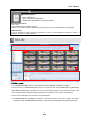
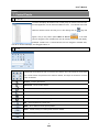
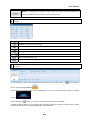
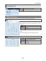
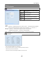
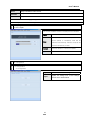
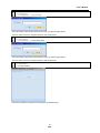
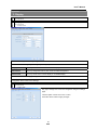
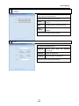
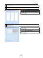
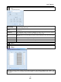
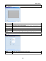
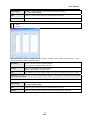
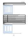
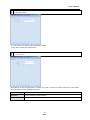
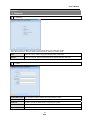
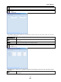
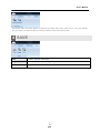
User’s Manual
Ver 1.00
1
User’s Manual
Table of Contents
1 Main.....................................................4
3 .Buzzer................................................... 17
4.Remote Update......................................... 18
1. Control Panels.............................................5
5.Configuration............................................ 18
1.Site List....................................................5
- 1 .Configuration...........................................18
2.PTZ ........................................................5
_1.Export Popup.......................................19
3.Color .......................................................6
_2.Import Setup Data..................................19
4.Search.................................................... 6
3. Display............................................................ 20
-1. Search Control...........................................7
1.Date/Time................................................20
-2. Goto Popup..............................................7
- 1 .Date/Time..............................................20
-3. Positions…...............................................8
- 2 .DST Time..............................................20
5. Thumbnail Search.......................................8
-3.NTP.....................................................21
6 . Log ......................................................10
2.OSD......................................................21
7.Event Log................................................10
3 . Event Display...........................................22
8.Event Search............................................................10
- 1 .Popup.................................................22
9.Favorite....................................................................11
- 2 .Monitor B Schedule...................................22
- 1 .Favorite (Rename Label)..............................11
4.Interval.................................................. 23
10.Bookmark................................................................11
4. Camera........................................................... 23
-1.Bookmark Public Popup................................12
1.Setup.....................................................23
11.Camera...................................................................12
-1.Copy Setting Popup...................................24
12.Audio.......................................................................12
2.Alarm In..................................................24
13.Popup Menu...........................................................12
- 1 .Setting................................................24
2 System Toolbar.........................13
- 2 .Action.................................................25
3.Alarm Out................................................26
1. Main................................................................13
- 1 .Setting................................................26
2. Layout.....................................................13
- 2 .Schedule.............................................
26
3. View....................................................... 14
4.Alarm Copy Setting Popup............................27
4. Popup Menu............................................. 14
5 . Video Loss..............................................28
3 Remote...........................................15
6 . PTZ......................................................28
7.Motion...................................................29
1. Setup Public Popup.......................................... 15
- 1 .Time Setting..........................................29
1.Copy Setting.............................................15
- 2 .Day, Night Setting.....................................30
2.Channel Select..........................................15
- 3 .Action.................................................30
2. Setup System................................................... 16
5. Record........................................................... 31
1.User Authority............................................16
1.Setup.....................................................31
- 1 .Authority................................................16
- 1 .Normal................................................31
2.Audio..................................................... 17
- 2 .Event.................................................
2
32
User’s Manual
- 3 .Pre-Event.............................................
33
- 4 .Panic.................................................
33
2.Schedule.................................................34
- 1 .Schedule Popup Page.................................35
3.Holiday...................................................35
- 1 .Holiday Popup.........................................36
6. Device............................................................. 36
1.RS-232C.................................................36
2.Keyboard Control.......................................37
3.Remote Control.........................................38
4.Smart Backup...........................................38
7. Network........................................................... 39
1.Notification...............................................39
2 .E-Mail....................................................39
3.Event.....................................................40
4.Stream...................................................41
- 1 .Total Setting...........................................41
- 2 .Detail Setting..........................................41
8. Backup........................................................... 42
1.Backup Status..........................................42
4 Save.................................................43
5 Public Menu................................44
1. CMS................................................................44
1.Setup System............................................44
2.Setup Remote...........................................45
- 1 .Add Site...............................................45
- 2 .Setup Port.............................................46
2. Customize Quick Access Toolbar......................46
1.Popup....................................................46
- 1 .More Commands.......................................46
- 2 .Customize..................................................47
3. Style............................................................... 48
6 Web Viewer.................................49
1. Remote Viewer................................................. 49
2. Remote Search................................................ 50
3
User’s Manual
PC Requirement
(Recommendation)
- Ram: 2 GB Above
- CPU: Core 2 Duo 2180E Above
- Graphic Card: ATI Radeon HD 2400 Pro Above
(Minimum Requirement)
- Ram: 1 GB
- CPU: Pentium4 Series or AMD Equivalent
- Graphic Card: Radeon, GeForce Series (which supports DirectX 9.0 and 720x480 texture mip-mapping)
(CMS Safemode)
If your PC specification doesn’t meet the requirement, you may try CMS Safemode. Please go to “Start” Æ
“Programs” Æ “CMS” Æ “CMS Safemode".
1 MAIN
1
2
3
<CMS Main screen>
1. The CMS Main Tool Bar has three (3) selectable tabs named "System", "Remote" and "Save".
2. There are seven (7) Control Panel options that you may select to view. They are Sites, PTZ, Log, Event Log,
Color, Search and Favorite. Upon selection, these Control Panels will appear on left and bottom section of the
GUI. They have a feature called Docking that fixes these control panels on its location without hiding it.
3. This is the area where live view and search view are displayed.
4. The Search Panel and Log Panel will appear on the bottom section of the GUI by default, and will be
separated in tabs. The Search Panel will display a calendar with red highlighted dates indicating recorded.
4
User’s Manual
[1] Main
1. Control Panels
1
1. Control Panels
1. Site List
The Site List displays all DVRs that are currently setup for remote connection with
the CMS application, and its cameras available for view. From the Site List Panel
) logo will
select the desired camera and drag it on to the viewing area. A (
appear, and you may select options Watch or Search (
).
If the DVR
name is dragged on the viewable area then all cameras for the DVR will display.
(Example: if DVR-172 is a 16 channel DVR, and it is dragged to viewable area,
then all 16 cameras will display from dragged location on.
1
1. Control Panels
2. PTZ
8 directional arrows allow the user to move the PTZ camera. The PTZ Camera is moved when
one of these arrows are pressed to the direction desired, and stops the movement if mouse
button is released.
Zoom In – Zoom In the camera
Zoom Out – Zoom Out the camera
Focus Near – Focus to near object.
Focus Far – Focus to far object.
Iris Close – Iris is closed to let in less light.
Iris Open – Iris is open to let in more light.
Set – Set PTZ presets on current view.
Goto – Go to selected camera preset position.
Clear – Preset memory for current preset chosen is deleted.
Name – Change name of selected preset.
PTZ – Save name and location of preset.
5
User’s Manual
Mouse – is used for PTZ control by a mouse. Move your mouse over to the selected PTZ
channel. Then left click and move the mouse to control the PTZ.
1
1. Control Panels
3. Color
Brightness – Controls brightness. (0~100)
Contrast – Controls contrast. (0~100)
Saturation – Controls saturation. (0~100)
HUE – Controls Hue. (0~100)
Sharp – Controls sharpness of picture. (0~100)
Up arrow is to increase the number, down arrow to decrease number.
Goes to Default settings. (50)
Saves settings.
1
1. Control Panels
4. Search
1) From the Site List Panel, select desired camera and drag it on to the viewing area. A (
and you may select option Search (
) logo will appear
).
2) Click the selected channel again to search individually. Then, you can see a red outline around the selected
channel.
3) Click the Refresh (
) button. You can then see recorded dates in red on the calendar.
4) Select the date by clicking on one of dates in red, and select the time by moving the vertical red bar to search
the recorded data. It will now automatically playback the recorded data.
6
User’s Manual
1
1. Control Panels
4. Search
-1. Search Control
GoTo – Define the date and time of desired view. (Refer to section 1.1.4.2)
Refresh – Request for the recorded data.
Zoom In Time Bar – Upon selection, the zoom in time bar will display the recorded time in shorter
increments
Zoom Out Time Bar – Time bar is shown back to hourly increments.
Search First – Moves to the first playable image.
Search Rewind – fast rewind.
Search Backward – play backward.
Search Backward Step – reverse to image before by picture increments.
Search Pause - Pause.
Search Forward Step – forward to image after by picture increments.
Search Forward – regular play.
Search Fast Forward – fast forward.
Search Last – moves to the last playable image.
Panoramic Search – displays every second of video in screen shots.
Continuous recording available.
Motion recording available.
Sensor recording available.
Alarm recording available.
Pre alarm recording available.
1
1. Control Panels
4. Search
-2. Goto Popup
Upon clicking on to the button you will launch the Go to Popup menu. This popup menu us used to select
a specific time and date.
7
User’s Manual
1
1. Control Panels
4. Search
-3. Positions
When you click the time table shown on Search Panel, recording data list will be shown. If you click the list, the
selected recording data will be shown on the screen.
1. Control Panels
1 5. Thumbnail Search
Thumbnail Search provides a faster and more efficient method to analyze recorded video data by
specifying user defined criteria. Image place holders, “Thumbnails”, will be displayed in sequence
according to the date, interval, and time range specified.
1) Select the desired channel by left clicking it with your mouse as shown below.
2) Left click the “Thumbnail Search” tab with your mouse located at the bottom section of the CMS
program. You will then see the “Thumbnail Search” window as shown below.
3) Select the Date (Figure 1), Time Range (Figure 2), Time Interval (Figure 3), and the Image Size (Figure 4)
of the Thumbnail screenshot.
2
1
3
4
8
User’s Manual
1. Use the Calendar to select a desired date.
2. Select the Time range (start time and end time) by using the slide bar.
3. Select the Interval (time interval) which displays still shots by a specified time. You may
choose 1min, 3min, 5min, 10min, 30min, and 1hour (ex. 1min. means 1 still shot per 1
minute of recorded video data.)
4. Adjust the Thumbnail Image size by using the slide bar. Moving the slide bar to the right
will increase the image size, and moving it to the left will decrease image size.
4) Click the Loading button to start loading recorded data from the DVR.
The blank image boxes will now display still screenshots as shown below.
5) Click a screen shot to retrieve the targeted data on the screen.
Click
9
User’s Manual
1
1. Control Panels
6. Log
In the Log control panel you may see logs generated while operating CMS application. There are check boxes
available to filter the desired types of logs to be shown on the window.
moves to the previous log page.
moves to the next log page.
moves to the first log page.
moves to the last log page available.
Searches all of log including the letters in the text bar.
log information will clear.
Saves log information in text file.
Shows frame per second of the selected channel.
1
1. Control Panels
7. Event Log
By clicking the Event Log tab, events captured by the connected DVR will be displayed.
1
1. Control Panels
8. Event Search
Start
Shows the start time.
End
Shows the end time.
Search
shows even list between start time and end time.
* A channel should be selected prior to Event Search.
10
User’s Manual
1
1. Control Panels
9. Favorite
Favorite option enables sites (off site DVR) to be added, deleted and edited.
Add
Adds currently connected site.
Edit
Rename current site information.
Remove
Deletes currently saved site information.
Load
Loads currently selected site on the list.
Save
Saves the information on current list.
1
1. Control Panels
9. Favorite
-1. Favorite (Rename Label)
You will see the window above upon adding or editing the site.
1
1. Control Panels
10. Bookmark
This function is similar to Favorite function.
You can add, edit or remove the list of search data.
Add : Adds the time of current search data.
Edit : Change the name of title.
Remove : Delete selected bookmark on the list.
Goto : Search the selected bookmark.
Update : During playback, the time of current search data will be updated on the list.
That is to day, it changes the time of bookmark search data.
11
User’s Manual
1
1. Control Panels
10. Bookmark
- 1.Bookmark Public Popup
This popup window will be seen, when you click Add or Edit button on the bookmark window.
1
1. Control Panels
11. Camera
Previous: shows previous channel display on the screen.
Next: shows next channel display on the screen.
Sequence: shows next channel display automatically.
1
1. Control Panels
12. Audio
Audio: click the checkbox to enable Audio function.
Two way Audio: click the checkbox to enable two way Audio.
1
1. Control Panels
13. Popup Menu
Right click the mouse on the control panel to display this pop up menu. Panels
then may be fixed in view location by selecting Docking option.
Floating
You may have the control panel float to move to desired location on the viewable window.
Docking
After moving the control panel into a certain location, and engaging the Docking option, your control
panel will be fixed to that viewable location.
Tabbed
Document
If the “Tabbed Document” option is not selectable, than the selected control panel cannot be tabbed
Auto Hide
Control panel will auto hide and will appear only when mouse is moved over the location.
Hide
Control panel will be hidden. The hidden panel will be visible again in "View" on "System Toolbar"
section. Upon selecting "View" select which panels to appear again.
12
User’s Manual
2 SYSTEM TOOLBAR
Default view of the system toolbar upon starting CMS application.
[2] System Toolbar
1. Main
Setup – Connection setting may be viewed and changed.
Connect – Connect site selected on control panel.
Disconnect – Disconnect site selected on control panel.
Search/Watch is used to choose type of viewable video type.
[2] System Toolbar
2. Layout
Video channel views are arranged in 1, 4, 6, 9, 10, 13, 16, 25, 32, 36, 49, 64, 128, Full, and Dual screen option
configurations.
The display formats are shown below
1 view
4 view
16 view
25 view
6 view
9 view
10 view
13 view
32 view
36 view
49 view
64 view
128 view
Full mode is shown in single channel view.
Dual mode stretches the video channels to the second monitor if connected.
13
User’s Manual
[2] System Toolbar
3. View
Each Control Panel is displayed by clicking on the corresponding check boxes.
Only the checked items may appear as a control panel on main view.
You may use the hide option or deselect the check box to hide the control panel.
If you check ‘All’, you can select all items at the same time.
[2] System Toolbar
4. Popup Menu
This is a popup menu will be shown by right-clicking on the Main toolbar.
- Add to Quick Access Toolbar – Enables to add a control bar to Quick Access Toolbar.
- Customize Quick Access Toolbar – Enables to customize Quick Access Toolbar.
- Show Quick Access Toolbar Above the Ribbon – Moves the Quick Access Toolbar below the System Toolbar.
- Minimize the Ribbon – Minimizes the control toolbar.
14
User’s Manual
3 REMOTE
Setup
Changes settings of DVR remotely.
Backup
Backup the data of a DVR remotely to a PC.
[3] Remote
1. Setup Public Popup
When accessing the remote “Setup” option, you will also be able to use copy features.
3
1. Setup Public Popup
1.Copy Setting
The copy settings feature allows you to copy the settings
from a single source channel, and apply them to other
channel(s).
From
The channel you wish to copy the settings from.
Properties
The attributes you wish to copy from the source
channel
To
The channel(s) you wish to copy the settings to.
(Note)
Selecting “Select All” will check all available channels.
3
1. Setup Public Popup
2. Channel Select
Select All
Selects all available channels
Ch. 1 ~ 16
The attributes you wish to copy from the source
channel
Set
Applies the changes to the selected
channel(s)
15
User’s Manual
[3] Remote
2. Setup System
3
2. Setup System
1. User Authority
User
Types of available users are Admin, Manager1 ~
3, and User 1 ~ 7.
Current
Password
input current password.
New
Password
input new password.
Confirm
Password
input new password again for confirmation.
Password
Check
checks the previous password and changes it to
the new password given.
( Note )
Admin : 1) Authority – Full rights are given to the “Admin” account. These rights cannot be disabled.
2) Admin may assign passwords or enable authority for Manager 1, 2, 3, and User 1 ~ 7.
Manager : 1) Authority – only the authority assigned by Admin will be permitted.
2) Manager may give User 1 ~ 7 authority or change password.
User : 1) Authority – only the authority assigned by Admin or manager will be permitted
3
2. Setup System
1. User Authority
-1. Authority
- Types of authorities available for the selected user.
- You may select the check box to give the corresponding authority to that user.
- “Select All” may be used to check all items.
- “Set” button is used to save the settings and apply it to the user account.
16
User’s Manual
3
2. Setup System
2. Audio
MIC Volume
Speaker
Selecting“On” enables the microphone, selecting “Off” disables the microphone, and you may use
the slider bar to increase or decrease the microphone volume.
Selecting“On” enables the speaker, selecting “Off” disables the speaker, and you may use the
slider bar to increase or decrease the speaker volume by channel.
The Slider bar will only be enabled when the radial button is set to "on".
Press the "Save" button to apply changes.
“Default" may be chosen to set all configurations to default values.
3
2. Setup System
3. Buzzer
This option enables an audible Beep noise for the selected events listed.
Select All
Select all events
Key Beep
Beep is enabled when key is pressed
Video Loss
Beep is enabled for video loss.
17
User’s Manual
Alarm
Beep is enabled for alarm events.
Motion
Detection
Beep is enabled for motion events.
Disk Full
Beep is enabled when HDD is full.
Press on the "Save" button to apply changes.
“Default" may be chosen to set all configurations to default values.
3
2. Setup System
4. Remot Updte
The current software version is displayed in this window
Open
click this button to select update file
click this button to initiate the update.
Start
*Once update is completed, DVR will be
rebooted automatically. Remote setup will be
closed automatically as well.
Cancel
Click this button to cancel the update.
Opens the file browser window
3
2. Setup System
5. Configuration
3
2. Setup System
5. Configuration
-1. Configuration
Export
Saves the current DVR settings to a data file.
Applies the settings from a DVR settings
Import
data file to the selected DVR
18
User’s Manual
3
2. Setup System
5. Configuration
-1. Configuration _1. Export Popup
The Export Setup popup window will be shown when you click the Export button.
You then create a file name and path where the data will be saved.
3
2. Setup System
5. Configuration
-1. Configuration _2. Import Setup Data
The Import Setup popup window will be shown when you click the Import button.
You then create a file name and path where the data will be saved.
3
2. Setup System
5. Configuration
-2. Factory Default
Click Factory Default to change a current setting to the default setting.
19
User’s Manual
[3] Remote
3. Display
3
3. Display
1. Date/Time
3
3. Display
1. Date/Time
-1. Date/Time
This menu allows you to remotely change the date and time of the DVR
The‘TIME ZONE’ setting may be changed by utilizing drop down list.
Display Format
you may choose how the date and time will displayed for remote DVR.
Date Format
you may change the order of year, month and date arrangement.
Time Format
you may choose 24 hour clock display or an AM/PM display.
Press the "Save" button to apply changes.
On the top right section there is drop down list where NTP and DST could be selected when selecting the
configuration tab for NTP or DST settings.
3
3. Display
1. Date/Time
-2. DST Time
Day light savings time could be configured using this settings
page.
The DST option can be set to “ON” or “OFF”
Press the "Save" button to apply changes.
20
User’s Manual
3
3. Display
1. Date/Time
-3. NTP
This settings menu is used to configure the Network Time
Server option for the remote DVR.
You set the NTP mode to “ON” or “OFF”
Server
Time server's TCP/IP information may be
inputted.
Port
Configure TCP port for the NTP server.
Sync.
Interval
Define the interval time for synchronization
attempts.
Press the "Save" button to apply changes.
3
3. Display
2. OSD
This settings menu is used to configure the OSD display in
Live mode and Playback mode.
If there is no operation by user during the
Time Out
selected
time,
OSD
will
disappear
automatically.
Select All
Selects all check boxes.
Language
Selects language to be displayed
Press the "Save" button to apply changes.
21
User’s Manual
3
3. Display
3. Event Display
3
3. Display
3. Event Display
-1. Popup
3
Monitor A
Set up Alarm, Motion popup for Video output.
Monitor B
Set up Alarm, Motion popup for Digital Spot.
Spot
Set up Alarm, Motion popup for Analog Spot.
3. Display
3. Event Display
-2. Monitor B Schedule
Split
Selects Full screen or 2x2 split.
Channel
Selects channels to be shown.
+, -
Add or delete setup page.
<< , >>
Goes to previous page or next page.
22
User’s Manual
3
3. Display
4. Interval
Sequence
The sequencing time between channels
(seconds)
PIP
The sequencing time for PIP mode (seconds)
Spot
Monitor
The sequencing time between channel for
the SPOT monitor (seconds)
Time Out
The specified time for the menu to exit to live
view when there is no activity
Press the "Save" button to apply changes.
“Default" may be chosen to set all configurations to default
values.
[3] Remote
4. Camera
3
4. Camera
1. Setup
Camera Setup
Covert
To specify a camera title (name), enter it into the “Camera Setup” column and press “Enter”
on your keyboard to apply. The “No.” section corresponds to the channel number for each
camera.
The “Covert” option is used to disable or enable a specified channel from being displayed
on the live view screen. The display will show as if there is Video Loss (Blue Screen). To
enable “Covert” for a specified channel(s), select the check box next to the corresponding
channel number. To disable “Covert”, uncheck the box next to the corresponding channel
number. Each channel(s) set to “Covert” will still be recorded.
Audio
The “Audio” section is used to specify an audio channel with a camera channel.
Save
Press the “Save” button to apply the changes made to this menu.
Default
Press the “Default” button to restore the factory default settings to this menu.
Copy Setting
Please refer to section 3.3.1.1 for detailed information.
23
User’s Manual
3
4. Camera
1. Setup
-1. Copy Setting Popup
Copy Setting
The “Copy Setting” option allows you to copy the settings from a specified channel, to the
other channel(s) of the DVR.
From
The “From” drop down menu is used to select the source channel you wish to copy the
settings from.
Properties
The “Properties” section contains the attributes you wish to copy from the source channel.
Please select the check box next to each attribute you wish to copy.
To
The “To” section is the channel(s) you wish to copy the settings to from the source (From)
channel.
OK
Press the “OK” button to apply the settings made to this menu.
Cancel
Press the “Cancel” button to discard the changes made to this menu.
3
4. Camera
2. Alarm In
3
4. Camera
2. Alarm In
-1. Setting
The Alarm In menu is used to specify how the DVR will respond to the sensor(s) installed on the system. You
may configure the Alarm In to correspond with the DVR speaker to initiate an audible beeping noise, or to a Relay
Out device.
24
User’s Manual
Type
You may specify each channel for the Alarm In port(s). There are three types you may
specify for each channel, N.O. (Normal Open), N.C. (Normal Closed), or Off.
Beep
The “Beep” option will allow the DVR to make an audible noise. To enable this feature,
check the box next to the corresponding channel number. Uncheck the box to the
corresponding channel number to disable it.
Alarm-Out
This option is to configure the Alarm-In sensor(s) with an Alarm-Out sensor(s). You may
select which Alarm-Out port will be triggered by clicking on the button next to the
corresponding channel. The options shown correlate to the Alarm-Out ports on the DVR.
Dwell Time
The “Dwell Time” section is used to set how long (in seconds 1~99) the Alarm Out sensor
will be activated for.
To access the “Action” menu, please use the drop down menu located on the upper right side.
Save
Press the “Save” button to apply the changes made to this menu.
Default
Press the “Default” button to restore the default factory settings.
Copy Setting
Please refer to section 3.3.1.1 for detailed information.
3
4. Camera
2. Alarm In
-2. Action
No
The “No.” specifies the Action channel number.
Record Channel
Is used to specify which channel(s) will be set to record on the event that the Alarm-In
channel is triggered.
Save
Press the “Save” button to apply the changes made to this menu.
Default
Press the “Default” button to restore the factory default settings to this menu.
25
User’s Manual
3
4. Camera
3. Alarm Out
3
4. Camera
3. Alarm Out
-1. Setting
The Alarm-Out menu is used to specify each channel that is set to an external sensor and its’ duration.
Type
You may specify each channel for the Alarm-Out port(s). There are three types you may
specify for each channel, N.O. (Normal Open), N.C. (Normal Closed), or Off.
Dwell Time
The “Dwell Time” section is used to set how long (in seconds 1~99) the Alarm-Out sensor
will be activated for.
To access the “Schedule” menu, use the drop down menu located on the lower left side.
Copy Setting
Please refer to section 3.3.1.1 for detailed information.
Save
Press the “Save” button to apply the changes made to this menu.
Default
Press the “Default” button to restore the factory default settings to this menu.
3
4. Camera
3. Alarm Out
-2. Schedule
26
User’s Manual
No.
Represents the schedule number.
Day
Is used to select the day of the week.
Start Time
Is used to specify when the schedule will begin.
End Time
Is used to specify when the schedule will stop.
Event
Is used to specify which type of event; Alarm, Motion, Video Loss, or All.
Alarm-Out
Is used to specify which Alarm-Out port will be triggered.
+ (plus) Key
Is used to add an additional schedule.
- (minus) Key
Is used to remove the selected schedule. Please check the box next to the corresponding
schedule number before choosing to remove it.
<< >>
Is used to jump to the previous or next page.
To access the Setting menu, please use the drop down menu located on the lower right side.
Save
3
Press the “Save” button to apply the changes made to this menu.
4. Camera
4. Alarm Copy Setting Popup
- This menu is used to configure the relay output channel
- After selecting the relay output channel, press “Set” to apply
27
User’s Manual
3
4. Camera
5. Video Loss
Ch.
Specifies the channel number.
Beep
The “Beep” option will allow the DVR to make an audible noise. To enable this feature,
check the box next to the corresponding channel number. Uncheck the box to the
corresponding channel number to disable it.
Alarm-Out
Is used to specify which Alarm-Out port will be triggered. (See Copy Setting Popup )
Copy Setting
Is used to copy the attributes from one channel, to the other channel(s).
Save
Press the “Save” button to apply the changes made to this menu.
Default
Press the “Default” button to apply the factory default settings to this menu.
3
4. Camera
6. PTZ
Channel
Is used to select the camera channel of the PTZ camera.
Protocol
Is used to select the protocol of the PTZ camera.
28
User’s Manual
Control ID
The “Control ID” is used to specify which PTZ camera to control. You use this option to
differentiate each PTZ camera. The control ID must match the ID set on the PTZ camera.
You may specify ID numbers 0 ~ 255.
Baudrate
The “Baud Rate” is the speed setting for data transfer from the PTZ to the
controlling device. The baud rate setting must match the PTZ camera. The
option you have are; 1200, 2400, 4800, 9600, 14400, 19200, 38400, 57600, and
115200.
Data Bits
The length of the data bits can be set from 5 ~ 8bits. This setting must match the PTZ
cameras setting for control.
Stop Bits
This represents the last bit. From this selection, you may choose 1 or 1.5 if the data bit is
5. If the data bit is 6 ~ 8, you may choose 1 or 2.
Parity
A parity bit is a bit that is added to ensure that the number of bits with value of one in a
given set of bits is always even or odd. Parity bits are used as the simplest error detecting
code.
3
4. Camera
7. Motion
3
4. Camera
7. Motion
-1. Time Setting
Day time
This section is used to specify the “Day Time” time range.
To access the “Day Setting” option, use the drop down menu located on the lower left side.
(See Copy Setting Popup )
Copy Setting
The “Copy Setting” option is used to copy the attributes from one channel to the other
channels of this menu.
Save
Press the “Save” button to apply the changes made to this menu.
Default
Press the “Default” menu to restore the factory default settings to this menu.
29
User’s Manual
3
4. Camera
7. Motion
-2. Day, Night Setting
Ch
Represents the channel number.
Min. Blocks
The “Min. Blocks” setting determines the minimum number of blocks from the motion mask
zone to be detected.
Sensitivity
There are 5 sensitivity level settings; Highest, High, Normal, Low, and Lowest.
Mask Zone
The “Mask Zone” refers to the area on a camera channel to enable or disable motion
detection.
Dwell Time
The “Dwell Time” option is used to specify how long (in seconds 1 ~ 99) the camera
channel will record for. (See Copy Setting Popup )
Copy Setting
Is used to copy the attributes of one channel to the other channel(s).
Save
Press the “Save” button to apply the changes made to this menu.
Default
Press the “Default” button to restore the factory default settings to this menu.
3
4. Camera
7. Motion
-3. Action
30
User’s Manual
No
Is the “Action” number.
Beep
The “Beep” option will allow the DVR to make an audible noise. To enable this feature,
check the box next to the corresponding channel number. Uncheck the box to the
corresponding channel number to disable it.
Alarm-Out
Is used to specify which Alarm-Out port will be triggered. (See Alarm Copy Setting Popup )
To access the “Day Setting” option, use the drop down menu located on the lower left side.
Copy Setting
Is used to copy the attributes of one channel to the other channel(s).
(See Copy Setting Popup)
Save
Press the “Save” button to apply the changes made to this menu.
Default
Press the “Default” button to restore the factory default settings to this menu.
[3] Remote
5. Record
3
5. Record
1. Setup
3
5. Record
1. Setup
-1. Normal
The Record menu is used to configure the record mode, resolution, video quality, and frame rate for each
individual channel.
Resolution
The resolution setting can be specified for each channel, the options are:
- NTSC: 704*480, 704*240, 352*480, 352*240
- PAL: 704*576, 704*288, 352*576, 352,288
Quality
There are 5 selectable video quality settings:
Highest, High, Normal, Low, and Lowest.
FPS
The “Frames Per Second” setting specifies how many frames will be recorded in 1 second.
CAUTION- Channels 1~4, 5~8, 9~12, and 13~16 are set in groups. The frame rate of the first and last channel
in a group must be equal.
Please use the drop down menu located on the upper left side to access the other record modes for configuration.
31
User’s Manual
Copy Setting
Is used to copy the attributes of one channel to the other channel(s).
(See Copy Setting Popup)
Save
Press the “Save” button to apply the changes made to this menu.
Default
Press the “Default” button to restore the factory default settings to this menu.
3
5. Record
1. Setup
-2. Event
The Event menu is used to configure the record mode, resolution, video quality, and frame rate for each
individual channel for Event triggered recording.
Resolution
The resolution setting can be specified for each channel, the options are:
- NTSC: 704*480, 704*240, 352*480, 352*240
- PAL: 704*576, 704*288, 352*576, 352,288
Quality
There are 5 selectable video quality settings:
Highest, High, Normal, Low, and Lowest.
FPS
The “Frames Per Second” setting specifies how many frames will be recorded in 1 second.
CAUTION- Channels 1~4, 5~8, 9~12, and 13~16 are set in groups. The frame rate of the first and last channel
in a group must be equal.
Please use the drop down menu located on the upper left side to access the other record modes for configuration.
Copy Setting
Is used to copy the attributes of one channel to the other channel(s).
(See Copy Setting Popup)
Save
Press the “Save” button to apply the changes made to this menu.
Default
Press the “Default” button to restore the factory default settings to this menu.
32
User’s Manual
3
5. Record
1. Setup
-3. Pre-Event
The “Pre-Event” menu is used to specify the pre-record settings when an event occurs.
Resolution
Specifies the image size in pixels
- NTSC: 720*480, 704*480, 704*240, 352*480, 352*240
- PAL: 720*576, 704*576, 704*288, 352*576, 352,288
Quality
Specifies the video quality. There are 5 options:
Highest, High, Normal, Low, and Lowest.
Type
Specifies they type of event; M(motion), A(alarm), M+A(motion+alarm).
Dwell Time
The “Dwell Time” option is used to specify how long (in seconds 1 ~ 30) the camera channel
will record for. (See Copy Setting Popup)
Copy Setting
Is used to copy the attributes of one channel to the other channel(s).
Save
Press the “Save” button to apply the changes made to this menu.
Default
Press the “Default” button to restore the factory default settings to this menu.
3
5. Record
1. Setup
-4. Panic
The “Panic” menu is used to specify the panic record settings when an panic record is engaged.
33
User’s Manual
Resolution
Specifies the image size in pixels
- NTSC: 720*480, 704*480, 704*240, 352*480, 352*240
- PAL: 720*576, 704*576, 704*288, 352*576, 352,288
Quality
Specifies the video quality. There are 5 options:
Highest, High, Normal, Low, and Lowest.
Type
Specifies they type of event; M(motion), A(alarm), M+A(motion+alarm).
Dwell Time
The “Dwell Time” option is used to specify how long (in seconds 1 ~ 30) the camera
channel will record for. (See Copy Setting Popup)
Copy Setting
Is used to copy the attributes of one channel to the other channel(s).
Save
Press the “Save” button to apply the changes made to this menu.
Default
Press the “Default” button to restore the factory default settings to this menu.
3
5. Record
2. Schedule
This menu is used to specify the time frame and record mode for the available channels.
Day
Is used to specify the day of the week.
Start Time
Is used to specify when the recording will begin.
End Time
Is used to specify when the recording will stop.
Mode
Is used to specify the type of recording.
Alarm, Motion, A+M (Alarm + Motion), Continue, M+C (Motion + Continue)
Channel
Is used to specify which channels.
+(Plus Key)
Is used to add an additional schedule.
-(Minus Key)
Is used to remove the selected schedule.
corresponding schedule before removing.
Update
Is used to apply the changes made to this menu.
34
Make sure to check the box next to the
User’s Manual
3
5. Record
2. Schedule
-1. Schedule Popup Page
Select All
This will select all available channels.
Ch 01 ~ Ch 16
You can individually select each channel.
Set
Will confirm the selections made to this menu.
3
5. Record
3. Holiday
This menu is used to specify any Holidays during the year.
Once a day is selected, a pop-up menu appears. (refer to section 5.3.1)
Select Day of Week
Is used to select the day of the week as a Holiday.
Save
Press the “Save” button to apply the changes made to this menu.
Default
Press the “Default” button to restore the factory default settings to this menu.
35
User’s Manual
3
5. Record
3. Holiday
-1. Holiday Popup
Cancel: Press “Cancel” to discard or close the menu.
- Ex) October / 1: April 1 Setting
- Ex) October / 1st/ Wed: April 1
- Confirm – Applies the setting.
Year: clears the entire year
Month: clears the entire month
[3] Remote
6. Device
3
6. Device
1. RS-232C
Parity
A parity bit is a bit that is added to ensure that the number of bits with value of one in a
given set of bits is always even or odd. Parity bits are used as the simplest error detecting
code.
36
User’s Manual
Stop Bits
This represents the last bit. From this selection, you may choose 1 or 1.5 if the data bit is
5. If the data bit is 6 ~ 8, you may choose 1 or 2.
Data Bits
The length of the data bits can be set from 5 ~ 8bits. This setting must match the RS-232
Device setting for control.
Baudrate
The “Baud Rate” is the speed setting for data transfer from the RS-232 Device to the
controlling device. The baud rate setting must match the RS-232 Device. The option you
have are; 1200, 2400, 4800, 9600, 14400, 19200, 38400, 57600, and 115200.
Save
Press the “Save” button to apply the changes made to this menu.
Default
Press the “Default” button to restore the factory default settings to this menu.
3
6. Device
2. Keyboard Control
Protocol
Is used to select the protocol of the keyboard controller.
Control ID
Is used to select the ID of the controller.
Parity
A parity bit is a bit that is added to ensure that the number of bits with value of one in a
given set of bits is always even or odd. Parity bits are used as the simplest error detecting
code.
Stop Bits
This represents the last bit. From this selection, you may choose 1 or 1.5 if the data bit is
5. If the data bit is 6 ~ 8, you may choose 1 or 2.
Data Bits
The length of the data bits can be set from 5 ~ 8bits. This setting must match the RS-232
Device setting for control.
Baudrate
The “Baud Rate” is the speed setting for data transfer from the RS-232 Device to the
controlling device. The baud rate setting must match the RS-232 Device. The option you
have are; 1200, 2400, 4800, 9600, 14400, 19200, 38400, 57600, and 115200.
Save
Press the “Save” button to apply the changes made to this menu.
Default
Press the “Default” button to restore the factory default settings to this menu.
37
User’s Manual
3
6. Device
3. Remote Control
- You can control up to 6 DVRs’ with your remote controller
- Press “Save” to apply the changes made
3
6. Device
4. Smart Backup
Smart Backup is used to specify back up settings if you wish to change the image quality of the video without
having to change the record settings of the DVR
Bitrate
Used to specify the video quality
Resolution
Used to specify the video resolution
Audio
You may select “ON” to include the audio capture with back up, or “OFF” to disable it
38
User’s Manual
[3] Remote
7. Network
3
7. Network
1. Notification
This menu is used to configure what type of events will be sent by the notification system.
Alarm, Motion Detection, Disk Full, Admin Password change, Video Loss, Power On/off
Save
Press the “Save” button to apply the changes made to this menu.
Default
Press the “Default” button to restore the factory default settings to this menu.
3
7. Network
2. E-Mail
Send E-Mail On/Off
You may either enable or disable the email notification option.
Send Server IP
Is used to specify the SMTP server.
Send Port
Is used to specify the SMTP server’s outgoing port number.
Send Server ID
Is used to specify the ID associated with the SMTP server.
Send Server PW
Is used to specify the associated password with the SMTP server.
39
User’s Manual
Sender
Recipient 1,
Recipient 2
Save
Default
3
Is used to specify who the notification was sent from.
You can have up to 2 email address for the recipient.
Press the “Save” button to apply the changes made to this menu.
Press the “Default” button to restore the factory default settings to this menu.
7. Network
3. Event
The Event menu is used to specify which IP address to send the DVRs’ event log to.
IP Address
Is the IP address to where the event log is sent to.
Mode
This setting is used to choose which events will be sent.
Alarm, Motion, Video Loss, or All
Port
Is used to specify the port number of the IP address to where the event log is sent to.
Channel
Is used to specify which channels the events will be logged from.
+ (plus key)
Is used to add additional schedules.
- (minus key)
Is used to remove the selected schedule.
be selected before removal.
Save
Press the “Save” button to apply the changes made to this menu.
40
The box next to the corresponding channel must
User’s Manual
3
7. Network
4. Stream
3
7. Network
4. Stream
-1. Total Setting
The Network Stream menu allows you to configure at which frame rate and video quality the DVR will
stream to the CMS client.
Total Setting Tab
Is a global setting for all channels.
FPS
Controls the frame rate for the network stream (frame rate may vary depending on
bandwidth)
Quality
Control the video quality for the network stream.
3
7. Network
4. Stream
-2. Detail Setting
Detail Setting Tab – Allows you to configure the network stream settings for the DVRs’ video channels in groups
of four (4).
FPS
Controls the frame rate for the network stream (frame rate may vary depending on
bandwidth)
41
User’s Manual
GOP
GOP (Group Of Pictures) determines the order in which the I, B, and P frames are
arranged. This will ultimately control which frames are streamed over the network
stream. The higher the GOP setting, the more frames are streamed.
Quality
Controls the video quality for the network stream.
[3] Remote
8. Backup
IP Address
Is the IP address to where the event log is sent to.
Network Port
Is the port number set on the DVRs’ network settings
User ID
Is the user ID stored on the DVR for remote access
User Password
Is the password stored on the DVR for remote access
DVR Information
Displays the total recording time available for back on the DVR, press “Update” to refresh
Back Up Setting
Is used to specify the back up start and end time, the path for where the video back up will
be saved on the client PC, the file name for the back up, and the maximum storage capacity
the back up file will use on the client PC’s hard drive.
3
8. Backup
1. Backup Status
Backup process can be stopped by clicking Backup Stop.
42
User’s Manual
The Remote Back Up option allows you back up the video data on the DVR to a PC over your network.
You can specify the date and time you wish to capture on the CMS client system.
4 SAVE
Print
Is used to Print the video image.
Image
Is used to convert the video image into BMP file format.
AVI
Is used to convert the video image into AVI file format.
43
User’s Manual
5 PUBLIC MENU
[5] Public Menu
1. CMS
This window will be invoked upon pressing the circular CMS icon. This is used to
hold frequent used options, shortcut keys, and other user configurable items and
keys.
(See Section System, Remote)
5
1. CMS
1. Setup System
You may select CMS's default language and font type.
If you have a checkmark for “Password Use”, when you log in next time, you may see “Login” popup window as
shown below. Please type you own password to log in.
If you want to change your password, please click “Change” button, then you may see “Change Password” popup
window as shown below. Then, you can change your password
44
User’s Manual
5
1. CMS
2. Setup Remote
You may configure, Add, Delete DVR systems connection properties here.
5
1. CMS
2. Setup Remote
-1. Add Site
In the Setup window if Add or Edit is selected then this popup will be invoked to configure connection
properties of the DVR.
Site Name
Define site name (nick name or site information)
DVR Type
Define type of DVR
Channels
Define number of cameras
IP Address
Define TCP/IP address for the DVR system.
45
User’s Manual
5
1. CMS
2. Setup Remote
-2. Setup Port
From the Add Site window and for Watch, Search, Setup Login buttons is selected then this "Setup Port"
window appears to configure Port, ID, and Password.
[5] Public Menu
2. Customize Quick Access Toolbar
is located besides circular CMS button. [see 5.2.1]
5
2. Customize Quick Access Toolbar
1. Popup
(Please see the next pages for details)
5
2. Customize Quick Access Toolbar
1. Popup
-1. More Commands...
46
User’s Manual
In this window you may define quick access items to appear on CMS button.
Selected quick access items are shown on the right section.
Commands
Add
Add quick access item.
Remove
Remove quick access item.
Reset
Select default quick access items.
Up and Down arrow key
Define the list order.
5
2. Customize Quick Access Toolbar
1. Popup
-2. Customize
Short cut key may be defined from Option then Customize button from tool bar.
From the command list selected functions that you want to customize.
Categories
Commands
Select the command that you want to change.
Current Keys
Displays the current short cut keys assigned for certain commands.
Press new Shortcut
Shows assigned short cut keys just pressed.
Set Accelerator for
Description
Shows the command's function and description.
Reset All
Reset all short cut key to the default values.
47
User’s Manual
[5] Public Menu
3. Style
You are able to select the color theme for the CMS’s User Interface
Blue Theme
Black Theme
Silver Theme
Aqua Theme
48
User’s Manual
6 WEB VIEWER
Web Viewer supports for Remote Viewer and Search.
Remote Viewer allows user to watch live display by internet connection.
Search allows user to watch recorded image by internet connection.
[6] Web Viewer
1. Remote Viewer
Remote Viewer allows user to watch live display by internet connection. User may input IP address of DVR on
the address section of web browser. When it runs properly, user may input Port, ID and Password on the Login
section. Then click ‘Connect’ allows connecting with DVR.
No
Function
Details
Description
Input DVR address into web browser then Web Viewer will
Input
1
DVR
IP
be started. (If it is first time to connect Web Viewer, it may
DVR connecting
address
need to install the program)
Viewer
Choose Remote
Remote Viewer shows Live display of DVR
selection
Viewer or Search
Search supports searching recorded date of DVR
Display
Video output
It shows Remote Viewer or Search.
2
3
User may connect with ‘Connect button’ after input Port,
Input
4
ID and P/W. And it may be disconnect with ‘Disconnect
Log In
IP,PORT,ID,PW
button’
5
Mode
Layout is arranged 1, 4, 8, 16 view.
Channel
User may choose specific channel
Channel Mode
49
User’s Manual
Change
the
It allows user to move the PTZ camera
direction
6
7
PTZ
Zoom, Focus, Iris
It allows user to adjust Zoom, Focus, Iris
Preset
It allows user to set and save Preset function.
Speaker On/Off
It allows selecting Audio on/off and Audio channel.
Audio
It allows communicating by Two-Way Audio when Mic
Mic
function is on.
[6] Web Viewer
2. Remote Search
When Web Viewer runs, user may find Search mode on upside menu bar. User may input IP address of your
DVR, Port, ID and Password then click ‘Connect button’ for connecting with DVR.
No
Function
Details
Input
1
DVR connection
Description
DVR
address
Input DVR address into web browser then Web Viewer will
be started. (If it is first time to connect Web Viewer, it may
need to install the program)
2
3
4
Choose Viewer or
Remote Viewer shows Live display of DVR
Search
Search supports searching recording date of DVR
Video output
It shows Remote Viewer or Search.
Input
User may connect with ‘Connect button’ after input Port,
IP,PORT,ID,PW
ID and P/W. And it may be disconnect with ‘Disconnect
Viewer select
Display
Log In
button’
50
User’s Manual
5
Mode
Layout is arranged 1, 4, 8, 16 view.
Channel
User may choose specific channel
Play panels
It allows operating all the playback function. (Forward,
Channel Mode
Backward, fast, pause, etc)
6
7
Playback
Audio
Go To Search
User may search detail time and date.
Search Bar
Define the date and time of desired recorded data.
Speaker On/Off
It allows selecting Audio on/off and Audio channel.
Mic
It allows communicating by Two-Way Audio when Mic
function is on.
Save
JPEG
Save current selected image by JPEG.
Save and print
image
the image
Save ASF video
Save the video of selected channel by ASF
Print image
Print current selected image
8
* Save and print function : Save and print enables when images are paused
ASF Video recording is started when click the play button after video saving button
selected.
ASF Video Recording stop to record when click the video saving button.
51
User’s Manual
52