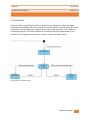
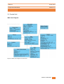
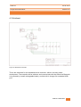
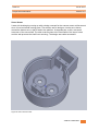
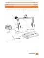
1
Sensur av hovedoppgaver Høgskolen i Buskerud og Vestfold Fakultet for teknologi og maritime fag Prosjektnummer: 2014-01 For studieåret: 2013/2014 Emnekode: SFHO3201 Prosjektnavn Video Coacher – An Automated Video Training System Utført i samarbeid med: Bjerknes Tanke og Teknikk Ekstern veileder: Jan Dyre Bjerknes Sammendrag: Video Coacher is an open-source training enhancement system for performing artists. It can track user movements and provide continuous video feedback for self review. The system can also assist artists while presenting, or teaching their skills to others. Visit us at www.videocoacher.com Stikkord: Automated Video Training Tilgjengelig: Ja Prosjekt deltagere og karakter: Navn Brian Opedal Jacob N. Berntsen Even Hørtvedt Christian Thue Eyvind S. Nistad Øystein V. Årsnes Karakter Dato: 12. Juni 2014 ________________ José M. M. Ferreira Intern Veileder _______________ Karoline Moholth Intern Sensor _______________ Jan Dyre Bjerknes Ekstern Sensor Catch 21 22.05.2014 Project Documentation Version 3.0 Project Documentation Version 3.0 Version: Date: Changes in document: Responsible: 1.0 05.02.14 Created document Brian & Jacob 2.0 01.04.14 Updated the document for second delivery Brian & Jacob 3.0 20.05.14 Changed document name and structure Brian & Jacob Formatted Jacob & Brian Name Signature Brian A. Opedal Jacob N. Berntsen Even Hørtvedt Christian Thue Eyvind Nistad Øystein Årsnes VIDEO COACHER 1 Catch 21 22.05.2014 Project Documentation Version 3.0 Executive Summary This is a collection of documents written for the Catch 21 Project. This collection of project documentation covers the documentation that is considered most important for the project execution and development. We start by giving an introduction to our project and what it is about. Next we include an overview of all the documents included in the Project Documentation. This overview informs you of how the project documents are organized, and offers a very brief description of each. Complete single documents are always found in the annex. We have done it this way to make it easy for anyone to use each individual document independently. It was felt that the organization we used would make a tidy and easy to read document collection. The full collection of documents include: Project Documentation 1. Product Backlog/Requirements Specification 2. Test Plan & Specification 3. Project Plan 4. Risk Analysis 5. Construction Document 6. Standards for Document and Code 7. Distribution of Assignment and Responsibilities 8. Scrumwise Sprints & Burndown Charts Overview 9. Sales Information Document 10. User Manual 11. Service and Development Manual 12. Technical Documents 13. After Analysis Document VIDEO COACHER 2 Catch 21 22.05.2014 Project Documentation Version 3.0 Table of Contents Glossary and Acronyms .......................................................................................................................4 Project Description .............................................................................................................................5 Project Documentation Overview: ......................................................................................................7 1. Requirements Specification .........................................................................................................7 2. Test Plan & Specification .............................................................................................................7 3. Project Plan .................................................................................................................................7 4. Risk Analysis ................................................................................................................................8 5. Construction Document ..............................................................................................................8 6. Standards for Document and Code ..............................................................................................8 7. Distribution of Assignment and Responsibilities ..........................................................................8 8. Sprints and Burndown Charts Overview ......................................................................................9 9. Sales Information Document .......................................................................................................9 10. User Manual..............................................................................................................................9 11. Service and Development Manual .............................................................................................9 12. Technical Documents .............................................................................................................. 10 13. After Analysis Document ......................................................................................................... 10 Annex ............................................................................................................................................... 11 A - Product Backlog/Requirement Specification............................................................................. 12 B - Test Plan & Specification .......................................................................................................... 37 C – Project Plan ............................................................................................................................. 78 D – Risk Analysis.......................................................................................................................... 102 E – Construction Document......................................................................................................... 118 F – Standards for Document and Code ........................................................................................ 167 G – Distribution of Assignment and Responsibilities .................................................................... 182 H – Scrumwise Sprint and Burndown Overview ........................................................................... 192 I – Sales Information Document .................................................................................................. 215 J – User Manual .......................................................................................................................... 227 K – Service and Development Manual ......................................................................................... 244 L – Technical Documents ............................................................................................................. 258 M – After Analysis Document ...................................................................................................... 327 VIDEO COACHER 3 Catch 21 22.05.2014 Project Documentation Version 3.0 Glossary and Acronyms Name Scrum Scrumwise Sprint Agile Description Framework for projects based on Agile development philosophies Scrum software tool - used to manage the project. Scrum - Fixed period of time, where work is broken down into distinct tasks. A set of iterative adaptive and collaborative software development oriented methods. PBI Product Backlog Item Siteswap Mathematical system for describing juggling VIDEO COACHER 4 Catch 21 22.05.2014 Project Documentation Version 3.0 Project Description This project is the last part of our bachelor degree and is intended to be a part of the transition from college education over to an actual work situation. For this reason the project work is intended to be as close as possible to a real engineering project. We will still have support from the HBV college and advisors throughout the project. But as a project group we are responsible for driving the project to completion, as well as deadlines, budget, communication with the client, and all other project responsibilities. The college has collaborated with the company Tanke og Teknikk so as to give us a real client and increase the project approximation to an actual work situation. The client Jan Dyre Bjerknes, at Bjerknes Tanke og Teknikk required a system to help with self review when practicing juggling technique. The client also wanted the system to assist him during lectures. He uses juggling as a means to inspire students to take an interest in scientific subjects. The system that we developed is called the “Video Coacher”, this system uses video feedback and processing to achieve the requirements we have been given by our client. To avoid any confusion while reading the documentation, we think it is important to explicitly describe the difference between the project we are doing and the product we are developing. Our project name is: “The Catch 21 Project”, this covers our project group and the work that we do. The product name, i.e. the actual physical system we are developing, is: “The Video Coacher”. Our group used Scrum as a framework. Scrum is generally light on documentation. However, in our project the documentation and engineering practices matter more to the college than the actual product. Some modification in how we implemented Scrum was required to fulfill the documentation requirements from the college. At the same time, we did not want to modify away the parts of Scrum that make it useful. We decided to modify the Scrum framework after the requirements of our bachelor project. VIDEO COACHER 5 Catch 21 22.05.2014 Project Documentation Version 3.0 Modify in the way that we have specific document requirements/PBI’s to fulfill. Scrum has the advantage that you do short but complete iterations and you get results at the end of every sprint (a Scrum period). This leads to fast feedback, which again means that we had the opportunity to fail fast, and hence improve fast. In Scrum we reiterate the development cycle every sprint. Daily Scrum meetings are time boxed and last maximum 15 minutes. The goal is to spend less time in meetings with everyone, and rather meet with specific group members as needed. Using a software tool called www.scrumwise.com helped us to implement the framework. To reiterate, the project’s purpose was to develop a system we call “The Video Coacher”. This system is intended to provide an adequate solution for our client Tanke og Teknikk. The project is done as a collaboration between our college HBV and Tanke og Teknikk. VIDEO COACHER 6 Catch 21 22.05.2014 Project Documentation Version 3.0 Project Documentation Overview: This section lists all the documents that are a part of the Project Documentation. It gives a brief description of each document and information about their placement in the annex. 1. Requirements Specification In our project we are using Scrum as a framework. In Scrum it is normal to use something called a product backlog. In Scrum the backlog document is equivalent to the requirements specification in a classic project management plan. The backlog contains all features that are of value to the product, including but not limited to the items you are likely to be able to implement during the project. All features, bug fixes and non-functional requirements can be added to the backlog. This document is found in annex A. 2. Test Plan & Specification The test plan plan document contains explanations of different kinds of tests. It also explains a variety of test strategies. The test document also holds all project test cases and their results. This document is found in annex B. 3. Project Plan The Project plan covers the objectives of the project, project variables, deliverables, resources, quality assurance, project framework, activities and milestones. Basically this document discusses all affairs in relation to planning and execution of the project. This document is found in annex C VIDEO COACHER 7 Catch 21 22.05.2014 Project Documentation Version 3.0 4. Risk Analysis The Risk Analysis document covers the general risks we might expect to encounter during our project. It also discusses possible ways to mitigate or avoid such risks. The document mentions the main challenges and solutions throughout the different sprint periods. This document is found in annex D. 5. Construction Document The construction document offers a description of the whole system as a general overview, but also as a more detailed design view. It uses various diagrams and explains the most important pieces of code. It covers the requirements demands and explains why some of these were not met. This document is found in annex E. 6. Standards for Document and Code The Standards document, lays the guidelines on how to write documents and code during the project. So as to get a more defined and coherent documentation, even though it originates from several group members. Integration of the data becomes more efficient as well. This document is found in annex F. 7. Distribution of Assignment and Responsibilities This document covers the different roles we have assigned to the project group members. It explains the tasks and responsibilities belonging to the different roles. The document was created so that it would be clear to the group members what was expected of the responsibilities they took on. This document is found in annex G. VIDEO COACHER 8 Catch 21 22.05.2014 Project Documentation Version 3.0 8. Scrumwise Sprints and Burndown Charts Overview The Sprints and Burndown Charts Overview, is a collection of burndown charts, and product backlog items for each individual sprint. This document is found in annex H. 9. Sales Information Document The Sales Information Document is a document that shows the main features and sales points of the Video Coacher product. The document makes a case for why the Video Coacher is the tool of choice when aiming to improve the quality of practice sessions. It covers the main impediments to quality practice sessions and some of the current solutions. This document is found in annex I. 10. User Manual The User Manual shows the user how to get started using the Video Coacher. It presents the user with the two different modes of operation, instructions and an overview of the controls with the help of vivid drawings. This document is found in annex J. 11. Service and Development Manual The Service and Development Manual contains instructions on how to service, maintain and develop the product. It is a document to be used as a resource if something goes wrong with the system. It also contains a parts list for use if any of the system parts needs to be replaced. This document is found in annex K. VIDEO COACHER 9 Catch 21 22.05.2014 Project Documentation Version 3.0 12. Technical Documents The Technical Documents is a collection of short documents looking at and comparing different parts used for the system. These documents lays the foundation for making informed choices when deciding on parts and describe the benefits of the various parts and the reasoning behind our choices. The documentation contains technical details of the parts used in the system which can then be used if the system needs to be updated or modified. Technical Document List Motor Tech Document Odroid Tech Document Camera Tech Document Camera Rig Tech Document Foot Controller Tech Document Wristband Tech Document Study of Motorized system Circuit Schematic Figures This document is found in annex L. 13. After Analysis Document The After Analysis is intended as a reflection over the project and process. It contains an evaluation of the different aspects of the project as well. And results compared against our initial goals for the project This document is found in annex M. VIDEO COACHER 10 Catch 21 22.05.2014 Project Documentation Version 3.0 Annex VIDEO COACHER 11 Catch 21 22.05.2014 Project Documentation Version 3.0 A - Product Backlog/Requirement Specification VIDEO COACHER 12 Catch 21 22.05.2014 Project Documentation Version 3.0 Product Backlog/Requirement Specification Version 3.0 Version: Date: Changes in document: Responsible: 1.0 10.02.14 Created document Christian 2.0 28.03.14 Updated the PBI table Christian 3.0 21.05.14 Color coding and PBI table Christian Formatting Jacob, Christian & Brian Name Signature Brian A. Opedal Jacob N. Berntsen Even Hørtvedt Christian Thue Eyvind Nistad Øystein Årsnes VIDEO COACHER 13 Catch 21 22.05.2014 Project Documentation Version 3.0 The requirements specification document is a document which describes what requirements are to be met, in accordance to the test specifications listed. As our project group is using Scrum all requirements which are made will be present in some shape or form in our product backlog. Thus our requirements specification document is essentially the product backlog. The product backlog is a prioritized list of requirements where each requirement has: An ID A user story An acceptance criteria Story points (SP) Comments The ID is being used to identify the requirement, so when talking about requirements in different documents only the ID will be used, and you need to find the ID in the product backlog to see the actual requirement. The user story is a way to justify the need for the requirement. One example: As a: user I want: to be able to adjust brightness settings. So I: can see my picture even though it’s dark. The acceptance criterion specifies what requirement must be met, before a user story is considered to be completed. If I build on the example above: Acceptance Criteria: Brightness can be adjusted by the user through a settings menu. Story points say something about the complexity of achieving the requirement. It’s all relative to other requirements, so a requirement with 4 points is twice as difficult as one with 2 points, even if the amount of work that needs to be done is the same. Comments are there in case you need to provide additional information to the user story, or things to take note of. Explanation of ID gaps and colors in the backlog VIDEO COACHER 14 Catch 21 22.05.2014 Project Documentation Version 3.0 Each PBI has its own ID number, and as you probably will notice there are gaps between listed ID's. The reason for this is that if you create a PBI on Scrumwise (the program we're using to organize the backlog) and delete it for any reason, the ID will still be taken. So if one item has the ID 40, and the next is 45, there might not even exist any items for 41-44. We've also chosen to not include every PBI from our backlog on Scrumwise due to some of them acting more like notes instead of normal PBI's. For instance we might have a PBI that says "Sprint goals for sprint 2", or "Ask Richard if he can print on Wednesday" . We feel including these in the official backlog wouldn't make much sense. There will also be a color scheme on the text of each PBI title, they will mean the following: PBI was scrapped and will not be included in the final build. PBI is not yet finished, but intended for final build. PBI has been successfully implemented in the final build. PBI doesn't relate to the product, but is still included due to its importance for the project. The PBI's not yet finished, but intended for final build will have a comment describing their status as of writing the final version of this document, they will usually be PBI's that we have begun, but might not be able to finish in time to include them in our final presentation. VIDEO COACHER 15 Catch 21 22.05.2014 Project Documentation Version 3.0 Product Backlog List of Tables Table 1: ID# 5 .......................................................................................................................18 Table 2: ID# 6 .......................................................................................................................18 Table 3: ID# 17 .....................................................................................................................19 Table 4: ID# 7 .......................................................................................................................19 Table 5: ID# 8 .......................................................................................................................20 Table 6: ID# 10 .....................................................................................................................20 Table 7: ID# 11 .....................................................................................................................21 Table 8: ID# 20 .....................................................................................................................21 Table 9: ID# 12 .....................................................................................................................22 Table 10: ID# 18 ...................................................................................................................22 Table 11: ID# 13 ...................................................................................................................23 Table 12: ID# 15 ...................................................................................................................23 Table 13: ID# 14 ...................................................................................................................24 Table 14: ID# 16 ...................................................................................................................24 Table 15: ID# 31 ...................................................................................................................25 Table 16: ID# 32 ...................................................................................................................25 Table 17: ID# 38 ...................................................................................................................25 Table 18: ID# 41 ...................................................................................................................26 Table 19: ID# 42 ...................................................................................................................26 Table 20: ID# 43 ...................................................................................................................26 Table 21: ID# 44 ...................................................................................................................27 Table 22: ID# 46 ...................................................................................................................27 Table 23: ID# 47 ...................................................................................................................27 Table 24: ID# 48 ...................................................................................................................28 Table 25: ID# 49 ...................................................................................................................28 Table 26: ID# 50 ...................................................................................................................29 Table 27: ID# 52 ...................................................................................................................29 Table 28: ID# 54 ...................................................................................................................30 Table 29: ID# 60 ...................................................................................................................30 Table 30: ID# 61 ...................................................................................................................30 Table 31: ID# 62 ...................................................................................................................31 Table 32: ID# 63 ...................................................................................................................31 Table 33: ID# 66 ...................................................................................................................31 Table 34: ID# 68 ...................................................................................................................32 Table 35: ID# 70 ...................................................................................................................32 Table 36: ID# 73 ...................................................................................................................32 Table 37: ID# 76 ...................................................................................................................33 Table 38: ID# 79 ...................................................................................................................33 VIDEO COACHER 16 Catch 21 22.05.2014 Project Documentation Version 3.0 Table 39: ID# 82 ...................................................................................................................33 Table 40: ID# 92 ...................................................................................................................34 Table 41: ID# 100 .................................................................................................................34 Table 42: ID# 103 .................................................................................................................34 Table 43: ID# 104 .................................................................................................................35 Table 44: ID# 106 .................................................................................................................35 Table 45: ID# 110 .................................................................................................................36 VIDEO COACHER 17 Catch 21 22.05.2014 Project Documentation Version 3.0 ID# 5 Control Camera Acceptance criteria: As a: developer. I want: to be able to use the ODROID X-2 to control the module camera. So I: can develop a system which uses specific functions on the camera. Story Points: 4 - Camera can be turned on/off, video stream can be started/stopped, and other relevant camera features can be controlled through the ODROID X-2. Comments: Table 1: ID# 5 ID# 6 Live Stream Acceptance criteria: As a: user. I want: to be able to use HDMI as output source to display devices. So I: can use any HDMI compatible display device to display the video. - Plugging any display device using HDMI into the ODROID X-2 when streaming should then display the streamed video. Story Points: 4 Comments: Table 2: ID# 6 VIDEO COACHER 18 Catch 21 22.05.2014 Project Documentation Version 3.0 ID# 17 Assemble & Test rig As a: developer. I want: to ensure all parts of the product are functioning properly and fit together. So I: can order new parts if some are missing/broken/unfit or alter other requirements if some parts limit the capability of the whole system. Acceptance criteria: - The rig can be (dis)assembled. - Moving parts should be able to do so without impediments. - Electronic components perform as expected. Comments: Should any component turn out to be malfunctioning or should there be missing parts new ones need to be ordered ASAP. Story Points: 2 Table 3: ID# 17 ID# 7 Save Recording Acceptance criteria: As a: user. I want: to be able to save recordings that I liked to a storage device. So I: can watch the recording at a later time. - Selecting some form of “save” option stores a recorded clip to the attached storage device. Story Points 4 Comments: Table 4: ID# 7 VIDEO COACHER 19 Catch 21 22.05.2014 Project Documentation Version 3.0 ID# 8 Transportable Storage As a: user. I want: to be able to bring with me recorded clips elsewhere. So I: can show other people my clips, even if they’re somewhere else. Acceptance criteria: - The storage device can easily be detached from the camera module and plugged into other compatible platforms and accessed there. Story Points 1 Comments: Table 5: ID# 8 ID# 10 Motion Detection As a: developer. I want: the camera to be able to detect specific objects. So I: can create software that makes the module follow the detected objects. Acceptance criteria: - Software can detect certain objects on video, either by colour or by shape. Comments: NOTE, THIS PBI HAS BEEN REPLACED BY ID#41 Story Points 16 Table 6: ID# 10 VIDEO COACHER 20 Catch 21 22.05.2014 Project Documentation Version 3.0 ID# 11 Camera module movement Acceptance criteria: Comments: As a: user. I want: to be able to move around without going off camera. So I: can move while practicing. - The camera follows the moving object and will not let it leave its POV unless physically impossible to follow further. Story Points 10 The should be a filter to stop the camera module from moving excessively when the detected object moves only short distances. Table 7: ID# 11 ID# 20 Website Acceptance criteria: As a: developer. I want: to have a website. So I: can share the current progress of the group with the world. - Members of the group can publish text and pictures on the website for the world to see. Story Points 8 Comments: Table 8: ID# 20 VIDEO COACHER 21 Catch 21 22.05.2014 Project Documentation Version 3.0 ID# 12 Automated Camera Module Acceptance criteria: As a: user. I want: to be able to practice without interacting with the camera module at all. So I: can just start my practice and keep on until I no longer feel like practicing, without breaks. - You can specify a delay prior to start, which will be kept throughout the practice session. - There’s a signal which tells when the current delay iteration ends. Story Points 12 Comments: Table 9: ID# 12 ID# 18 Easy Transport Acceptance criteria: Comments: As a: user. I want: to be able to fit the rig with the camera module into my car. So I: can take it with me wherever I go. - Rig and camera module can be disassembled (relatively quick) and fit into any normally sized car. Story Points 4 This PBI is one of the last prioritized ones of those to be included in the final build, so we haven't worked on it yet, but still intend to include it. Table 10: ID# 18 VIDEO COACHER 22 Catch 21 22.05.2014 Project Documentation Version 3.0 ID# 13 Slow Motion As a: user. I want: to be able to watch myself in slow motion. So I: can better see the small details when practicing. Acceptance criteria: - You can tag a setting to stream in slow motion. - Using slow motion does not make displayed video and recorded video go out of synch. Story Points 8 Comments: Table 11: ID# 13 ID# 15 Metronome As a: user. I want: to get some help keeping the beat/rhythm. So I: can tighten up my practice routines. Acceptance criteria: - You can choose to have a metronome where you specify its BPM. Comments: If a metronome is integrated it could be useful to include several extra beats as well, such as off beats, triplets etc. Story Points 8 Table 12: ID# 15 VIDEO COACHER 23 Catch 21 22.05.2014 Project Documentation Version 3.0 ID# 14 Pause, forward, rewind As a: user. I want: to be able to navigate through the video stream. So I: can watch exactly what I want whenever I want. Acceptance criteria: - You can pause, rewind and forward the stream. - Camera can continue recording even though the feed is paused/forwarding/backwarding. - Reaching either the end or beginning of the session/time limit pauses the video. Story Points 12 Comments: Table 13: ID# 14 ID# 16 Multiple Angles As a: user. I want: to be able to see my practice from multiple angles, including first person. So I: can see myself from different angles without doing several recordings. Acceptance criteria: - The user can specify which camera he/she wants to see at any given moment. - The user can choose to see all video streams simultaneously on a single screen. Story Points 12 Comments: Table 14: ID# 16 VIDEO COACHER 24 Catch 21 22.05.2014 Project Documentation Version 3.0 ID# 31 Stream Delay As a: user. I want: to be able to set a delay on the stream. So I: can practice, and then just stop and watch myself without interacting with the module. Acceptance criteria: - The user can set a delay, and the stream will be delayed by that much before being displayed. Story Points 8 Comments: Table 15: ID# 31 ID# 32 Camera Zoom As a: user. I want: to be able to zoom in on the video. So I: can see more details. Acceptance criteria: - You can zoom in on the picture. Story Points 16 Comments: Table 16: ID# 32 ID# 38 Juggling Beat Histogram As a: user. I want: to see my average juggling beat. So I: can tighten up my practice routines. Acceptance criteria: - The user can see a visual representation of his beat pattern on the screen. - There should also be a visual representation of what should be the current beat, based on the average beat. Story Points 20 Comments: Table 17: ID# 38 VIDEO COACHER 25 Catch 21 22.05.2014 Project Documentation Version 3.0 ID# 41 Color Recognition Acceptance criteria: As a: user. I want: system to be able to detect certain colors so it can track them. So I: can wear a certain item and the system will be able to know where I am in the frame. - When the camera is filming the system should be able to detect a given color and where in the frame it is located. Story Points 16 Comments: Table 18: ID# 41 ID# 42 Video Stream Interface As a: developer. I want: the system to be able to handle data coming from the webcamera. So I: can access and manipulate the video stream. Acceptance criteria: - Using the interface one can output the incoming data stream, as well as save it to file. Story Points 16 Comments: Table 19: ID# 42 ID# 43 Tilt & Pan Servo Interface As a: developer. I want: to be able to operate the servo’s through software code. So I: can create an automated system using servos. Acceptance criteria: - One can enter parameters to the interface and it will move the servo’s in the correct manner. Story Points 12 Comments: Table 20: ID# 43 VIDEO COACHER 26 Catch 21 22.05.2014 Project Documentation Version 3.0 ID# 44 Camera Platform Motor Interface As a: developer. I want: to be able to operate the motor through software code. So I: can create an automated system using a motor. Acceptance criteria: - One can enter parameters to the interface and it will move the motor in the correct manner. Story Points 16 Comments: Table 21: ID# 44 ID# 46 Remote Control Rig As a: developer. I want: to be able to test the motor and servo interfaces properly. So I: can demonstrate their capabilities through demonstrations. Acceptance criteria: - One can remote control the servo’s and motor with a PlayStation 2 controller. Story Points 12 Comments: Table 22: ID# 46 ID# 47 GitHub As a: developer. I want: to have version control and backup for my code. So I: will not lose any working code to mishaps. Acceptance criteria: - All programmers can push and pull successfully to GitHub. Story Points 6 Comments: Table 23: ID# 47 VIDEO COACHER 27 Catch 21 22.05.2014 Project Documentation Version 3.0 ID# 48 Cable Routing As a: developer. I want: to ensure cables experience as little stress as possible. So I: can deliver a sturdy product that does not eat itself when running. Acceptance criteria: - Cables attached to moving parts never tangles or get bent in sharp angles. This is going to be one of the last things we do, as it depends on the rest of the physical product to be more ore less finished. Comments: Story Points 8 Table 24: ID# 48 ID# 49 Create Parts & Datasheets Document Acceptance criteria: Comments: As a: user. I want: to be able to see what parts my product consists of, and how they operate. So I: can order new parts and properly operate them if something breaks down. - Document is accepted by product owner as representable. Story Points 4 Table 25: ID# 49 VIDEO COACHER 28 Catch 21 22.05.2014 Project Documentation Version 3.0 ID# 50 Create User Manual As a: user. I want: a manual for the product. So I: can learn about the functions and uses it offers. Acceptance criteria: - Manual is accepted by product owner as representable. Story Points 4 Comments: Table 26: ID# 50 ID# 52 Design Software Structure Acceptance criteria: As a: developer I want: a clear overview of the design of the software. So I: can implement software in a good way. - UML diagram is easily understood and a teacher with software background accepts the design as a good one. Story Points 6 Comments: Table 27: ID# 52 VIDEO COACHER 29 Catch 21 22.05.2014 Project Documentation Version 3.0 ID# 54 Create System Use Case Diagram Acceptance criteria: As a: developer. I want: to be able to present the use of the product to other people. So I:Can easily explain what the product does. - UML diagram is easily understood and a teacher with software background accepts the design as a good one. Story Points 6 Comments: Table 28: ID# 54 ID# 60 Create Camera Mount casing Acceptance criteria: As a: user. I want: the camera to be steady when moving. So I: can move and still see myself clearly. - Image is stable when the platform moves and changes speed/direction Story Points 12 Comments: Table 29: ID# 60 ID# 61 Create Odroid Casing Acceptance criteria: Comments: As a: user. I want: critical parts of the system to be protected. So I: don’t have to worry about accidentally coming into contact with critical parts. - Odroid operates normally without overheating or being susceptible to exterior trauma (within reason, of course). We have begun designing the casing, but haven't finished the design & printed it out yet. We will do this if time allows it, it's not highly prioritized as of now. Story Points 8 Table 30: ID# 61 VIDEO COACHER 30 Catch 21 22.05.2014 Project Documentation Version 3.0 ID# 62 Create Circuit Boards Acceptance criteria: Comments: As a: developer. I want: circuit boards. So I: don’t have to use breadboards and loose wires to operate the system. - Circuit boards successfully run the system. After talking with our external advisor we were told having physical circuit boards weren't very important, so we're going to design them, but not buy them for the final product. Story Points 12 Table 31: ID# 62 ID# 63 Create Cable Interfaces Acceptance criteria: Comments: As a: user. I want: easily identify where cables are supposed to be plugged in. So I: don’t accidentally insert a cable into the wrong plug and break something. - Manual is accepted by product owner as representable. This PBI corresponds with the PBI#61Odroid Casing, so we've not included this yet. It will happen whenever Odroid Casing happens. Story Points 6 Table 32: ID# 63 ID# 66 Improve Stepper Motor Performance As a: developer. I want: to make sure the stepper motor works optimally. So I: can use most of the potential in the hardware. Acceptance criteria: - Both external and internal advisor agrees that the stepper motor is operating as well as we can hope for. Story Points 16 Comments: Table 33: ID# 66 VIDEO COACHER 31 Catch 21 22.05.2014 Project Documentation Version 3.0 ID# 68 User Study Acceptance criteria: As a: developer. I want: to see what the potential marked desires from a product such as ours. So I: can create a product that meets customer’s desires. - Complete a survey online as well as through connections known to be interested in the product. Story Points 4 Comments: Table 34: ID# 68 ID# 70 Make Current Software Multithreaded As a: developer. I want: to be able to fully utilize the power of the ODROID X-2 So I: can perform more advanced operations with the system. Acceptance criteria: Comments: - System runs on as many threads as specified in the design. Story Points 16 Table 35: ID# 70 ID# 73 Create Interface for Arduino & Android Acceptance criteria: Comments: As a: developer. I want: the ODROID X-2 and the Arduino Nano to be able to communicate. So I: can run software on both platforms at the same time. - System runs on both platforms at the same time. Story Points 12 Table 36: ID# 73 VIDEO COACHER 32 Catch 21 22.05.2014 Project Documentation Version 3.0 ID# 76 Put Everything Together Acceptance criteria: Comments: As a: developer. I want: to run all software and hardware together, in one bundle. So I: can run the system as a whole - System runs all modules at once, without problems. Story Points 16 Table 37: ID# 76 ID# 79 Create New Motor Library As a: developer. I want: to optimize the motor So I: have a motor that performs smoothly and reliably. Acceptance criteria: Comments: - Motor runs with interrupt driven code. Story Points 10 Table 38: ID# 79 ID# 82 Wristband Acceptance criteria: Comments: As a: user. I want: to be able to control the system from a distance. So I: don't have to access the computer every time I'm using the system. - The system can be controlled from a distance by using a wristband. We've started designing the wristband, but we will not finish the physical parts as there's no time. Story Points 12 Table 39: ID# 82 VIDEO COACHER 33 Catch 21 22.05.2014 Project Documentation Version 3.0 ID# 92 Foot pedal Acceptance criteria: Comments: As a: user. I want: to be able to control the system from a distance. So I: don't have to access the computer every time I'm using the system. - The system can be controlled from a distance by using a foot pedal board. We've printed, assembled and finished the hardware aspect of the foot pedal and we will implement the necessary software between the delivery of this document and the final presentation. Story Points 10 Table 40: ID# 92 ID# 100 Implement PID Controller Acceptance criteria: As a: developer. I want: make the motion tracking as smooth as possible. So I: don't have to deliver a system with sub-par motion tracking. - The camera tracks the user in a smooth manner using a PID controller. Story Points 20 Comments: Table 41: ID# 100 ID# 103 Battery Solution for Odroid As a: user. I want: don't want the Odroid to reset every time it's unplugged. So I: can save files with the correct time format. Acceptance criteria: Comments: - Clock doesn't reset when the Odroid is unplugged. This is also one of the lowest prioritized PBI's that we still want to include, but don't have the time to implement before final delivery. Story Points 12 Table 42: ID# 103 VIDEO COACHER 34 Catch 21 22.05.2014 Project Documentation Version 3.0 ID# 104 Define User Environment Requirements Acceptance criteria: As a: user. I want: to know what conditions is required for the system to work optimally. So I: don't set up the system in the wrong environment and experience technical difficulties as a result. - The user manual includes the requirements set for proper use of the system. Story Points 4 Comments: Table 43: ID# 104 ID# 106 Camera Position Routine Acceptance criteria: Comments: As a: developer. I want: the software to be able to calibrate the position of the motor/camera. So that: the system at any given time knows where the camera is located. - It is possible to print out the exact location of the motor during runtime. We've finished the hardware part, we've got switches at the end of each side of the slider and we will implement the necessary software between the delivery of this document and the final presentation. Story Points 14 Table 44: ID# 106 VIDEO COACHER 35 Catch 21 22.05.2014 Project Documentation Version 3.0 ID# 110 Manuals Acceptance criteria: As a: user. I want: manuals covering the different aspects of the system. So I: or other parties can read up on how to use system. - There are manuals covering the following aspects: User manual, Service and Development and a Sales Information Story Points 4 Comments: Table 45: ID# 110 VIDEO COACHER 36 Catch 21 22.05.2014 Project Documentation Version 3.0 B - Test Plan & Specification VIDEO COACHER 37 Catch 21 22.05.2014 Project Documentation Version 3.0 Test Plan & Specification Version 3.0 Version: Date: Changes in document: Responsible: 1.0 05.02.14 Created document 2.0 01.04.14 Refurbished the document Øystein, Christian & Even Brian & Jacob 3.0 20.05.14 Added test cases and updated text Formatting Name Øystein Jacob & Brian Signature Brian A. Opedal Jacob N. Berntsen Even Hørtvedt Christian Thue Eyvind Nistad Øystein Årsnes VIDEO COACHER 38 Catch 21 22.05.2014 Project Documentation Version 3.0 Table of Contents List of Tables ..................................................................................................................................... 39 List of Test Reports ........................................................................................................................... 40 Glossary and Acronyms ..................................................................................................................... 41 1. Importance of Testing ................................................................................................................... 42 2. Test Methods and Artifacts ........................................................................................................... 43 2.1 Levels of Testing ...................................................................................................................... 44 2.2 Static and Dynamic Testing ...................................................................................................... 45 2.3 The Box Approaches ................................................................................................................ 45 2.4 Functional Tests ...................................................................................................................... 46 2.5 Usability Test........................................................................................................................... 46 2.6 Code Swapping........................................................................................................................ 46 2.8 Ad-hoc .................................................................................................................................... 47 2.9 Bug Reporting ......................................................................................................................... 47 3. Test Specifications ........................................................................................................................ 48 3.1 Cross Reference Table ............................................................................................................. 49 3.2 Test Reports ............................................................................................................................ 51 List of Tables Table 1: Cross Reference Table ......................................................................................................... 50 Table 2: Form Template .................................................................................................................... 51 VIDEO COACHER 39 Catch 21 22.05.2014 Project Documentation Version 3.0 List of Test Reports Test Report 1: Camera Controls Test ................................................................................................. 52 Test Report 2: Live Stream Test ......................................................................................................... 53 Test Report 3: Rig: Build Quality Test V1 - 3....................................................................................... 55 Test Report 4: Rig: Operation V1 - 3 .................................................................................................. 57 Test Report 5: Low Repetition Mode ................................................................................................. 58 Test Report 6: Camera Tracking ........................................................................................................ 59 Test Report 7: Servo Control Test ...................................................................................................... 60 Test Report 8: Motor Control Test..................................................................................................... 61 Test Report 9: PS2 Controller Test ..................................................................................................... 62 Test Report 10: Servo house Test ...................................................................................................... 63 Test Report 11: Make Current Software Multithreaded V1- 7 ............................................................ 66 Test Report 12: Color Recognition V1 - 2 ........................................................................................... 67 Test Report 13: Odroid to Arduino Communication........................................................................... 68 Test Report 14: Interrupt based Motor Driver with Input .................................................................. 69 Test Report 15: Current Management V1 - 3 ..................................................................................... 71 Test Report 16: Test Adafruit Motor Shield ....................................................................................... 72 Test Report 17: Increased Max Speed ............................................................................................... 73 Test Report 18: PSU Replacement Test V1 - 4 .................................................................................... 75 Test Report 19: Stream Delay Implementation .................................................................................. 76 Test Report 20: Use of Foot Controller .............................................................................................. 77 VIDEO COACHER 40 Catch 21 22.05.2014 Project Documentation Version 3.0 Glossary and Acronyms Name Description BBT Black Box Testing CS Code Swapping IA Internal Advisor OEM Original Equipment Manufacturer PBI Product Backlog Item QA Quality Assurance SW Software Agile Refers to development methods based on iterative and incremental development. Originates in Software development. TBA To be announced Scrum An agile project development model WBT White Box Testing VIDEO COACHER 41 Catch 21 22.05.2014 Project Documentation Version 3.0 1. Importance of Testing When working on a large projects, individual parts and software units are often developed separately before being merged together into one integral system. Even with plans and specifications to guide the process along, it is easy for developers to lose sight of the goal and develop components that do different things from what was intended, or in worst case components that are not compatible with one another. Various tests are therefore required at any level of development, including upon completion, to verify that all components and functions meet the product specifications and design standards, as well as being fail-checked before unit integration and ultimately final product delivery. The tests to pass for this project, and the methods to test by, will be presented in this document. The purpose of testing can be summed up by two words: Verification and Validation. Verification involves confirming that the system complies with the specifications, whereas validation entails confirming that the system performs according to customer expectations. If validation fails, it is not necessarily because the system is broken, but rather that the specifications were not correctly defined to begin with. If however verification fails, it would result of a design error or mean that the system is broken, incomplete or otherwise unusable. VIDEO COACHER 42 Catch 21 22.05.2014 Project Documentation Version 3.0 2. Test Methods and Artifacts This section will go through the testing strategy we have laid, and the testing methods that go with it. We will briefly describe the methods we have included and explain why we have included them. This strategy is mainly based on a Wikipedia article about software testing [2], and follows that article’s structure quite closely. We have not included all the methods the article lists, as some methods are simply too large in scope for this project and others do not seem relevant to us. Even though these methods originated with the vibrant software communities of the early nineties, and have been developed specifically for the creation of software, we believe that some of these test approaches are universal. We use the Scrum development model, which is an Agile model, and we have strived to deliver a complete presentable product at the end each sprint. Because of this, we have been forced to adapt an Agile testing strategy. This means that we have try to go through all levels of testing within each sprint as an integral part of the development. The strategy has been a bottom-up approach, testing every new part or unit in isolation before combining it with other parts. When two independently tested parts have been combined it has been considered a new part and we have run an integration test to see whether the merger went well. VIDEO COACHER 43 Catch 21 22.05.2014 Project Documentation Version 3.0 2.1 Levels of Testing Unit Testing – This is the lowest level where we test the smallest components of our system in isolation. The smallest components of our system will largely consist of single units of code or classes with one specific function. Besides static inspection, unit tests will also be functional dynamic tests where we run various dummy inputs to see if we receive the expected outputs. By verifying that each unit behaves correctly it ideally makes the next test level less complex, as it reduces it to checking interaction between units. Integration Testing – Here we test how newly integrated units interact with other units of an existing system or subsystem, and we seek to verify that the interfacing and pathways between them are correct and behave the way they should. Integration tests are done iteratively, i.e. every time we add something new. This allows us to identify bugs immediately as well as being able to placing them in relation to a specific incident. Functional tests at the integration level may often be the same ones used at the unit level, except that real data inputs from other units is used instead of dummy ones. System Testing – This is the highest test level of the developmental stage, where we test the full system for all its current functionalities. This level is also where we verify that it works according to the requirements. Tests at this level will mostly be functional and performance oriented by running user scenarios, and we do not anticipate having to look at source codes at this level. Acceptance Testing – This is the highest level of testing, where we present the latest fully tested version of the product for our client, and where the product has at least one new or enhanced function. Until all high priority functions have been completed, the product is considered an alpha. We intended to conduct one acceptance level test at the end of each sprint, but have not been able to fulfill this goal. The acceptance tests were intended to help us verify that the product was being developed in accordance with the requirement specifications. Officially we haven’t held an acceptance test yet, but we have been in close dialog with the client throughout and invited him over for demonstrations, upon which he have given us valuable feedback. VIDEO COACHER 44 Catch 21 22.05.2014 Project Documentation Version 3.0 2.2 Static and Dynamic Testing Static tests are done without actually activating any parts or software, and it have as such been hard to make a formal strategy for how and when to conduct them. They were intended to expose mistakes and discrepancies of our designs early on, and the most frequent approach to avoid this has been sharing work and peer reviewing. Static tests have let us verify that what we have built does not diverge from the product requirements, as well as validating that the requirements themselves are in fact correct. Dynamic testing is when we run functioning parts or units of software that have been assembled, at any level, to see how it behaves. Errors have been reported in our test results and work logs. Dynamic testing have taken up an increasing portion of the allocated time for testing every sprint as the project have continued to expand in complexity. 2.3 The Box Approaches There are basically two points of view when considering test cases; one being looking at the system from the outside and the other looking at it from the inside. They are called Black Box Testing and White Box Testing respectively, and most of our test cases have fallen in under the former. Black Box Testing Black Box testing methods are any testing procedure that examines a system without any knowledge of its inner structure. It consists mainly of running functional tests on the system, but there exists non-functional and even static aspects as well. Typically when performing Black Box tests you work directly with the system’s user interface to provide inputs and examining outputs or responses. Lower level tests where there’s no actual system to run may also be conducted in safe software development environments or by simulation. Black Box test cases are usually generated directly from external descriptions of the system’s requirements, which in our case is the user stories related to our Product Backlog. No knowledge of how the system or source code operates internally is required; the tester needs only be aware of what the unit or system is supposed to do, but he does not need to know how it does it. Black Box tests make up most of our system and subsystem testing, and all functional testing. VIDEO COACHER 45 Catch 21 22.05.2014 Project Documentation Version 3.0 White Box Testing White Box testing is the complete opposite of Black Box, and consist of methods for detailed and structured investigation of inner structure and code, i.e. how a program/circuit does what it does. We have not spent much time on such in depth investigation. 2.4 Functional Tests Functional tests are the form of Black Box testing that we have conducted most frequently. They are the type of tests that have their test cases based directly on the system’s functional requirements. Functional tests describe what a system or function does, and by passing the test we verify that system complies with the requirements. 2.5 Usability Test Usability tests are a special kind of functional test, which does not concern itself with whether the product works or not, but rather how easy it is to operate. Since we intend to create a product that is easy and hassle free to use, we have certain usability criteria to pass at the acceptance level as well to consider. 2.6 Code Swapping Code swapping is a static form of code review where upon completion of a software unit. It is common knowledge that the quickest way to spot mistakes in any text format is to have someone else read it. The pair-reviewer’s task was to look for common mistakes and structural weaknesses that inhibit evolvability of the product, and otherwise lines that deviated from the code standard. VIDEO COACHER 46 Catch 21 22.05.2014 Project Documentation Version 3.0 2.8 Ad-hoc Since beginning of the project, before plans and strategies had formally crystallized, the team had early access to several parts and components, referred to as OEM. This meant that we were able to start familiarizing ourselves with these components’ capabilities by running improvised tests on them on our own initiative. These tests have been done without any test plan or test scenario to go by, and the main purpose behind them has been to learn more about these component’s specifications and how they operate etc, before making them part of our system. Ad-hoc testing have continued to be practiced through the project and their results have been reported in work logs. 2.9 Bug Reporting Bugs have been reported in test results and work logs. VIDEO COACHER 47 Catch 21 22.05.2014 Project Documentation Version 3.0 3. Test Specifications This section contains the test reports for all the tests that has been conducted during the course of this project. The reports include a short description of what has been tested, the test method and approach, as well as acceptance criteria. VIDEO COACHER 48 Catch 21 22.05.2014 Project Documentation Version 3.0 3.1 Cross Reference Table The following table cross references all the test reports listed in this document with the user stories they originate from. Gray rows are test cases that is either not yet conducted or outdated. Test ID User Story ID Test Name No.Tests Runs 01 05 Camera Control 1 02 06 Live Stream 1 03 17 Rig: Build Quality 3 04 -- Rig: Operation 3 05 07 Save Recording - 06 08 Low Repetition Mode 1 07 33 Remote Controller - 08 09 Remote Control - 09 10 Camera Tracking 1 10 11 Stalking Camera SW - 11 11 Stalking Camera - 12 20 Website - 13 12 Automatic Mode - 14 18 Rig Portability - 15 13 Slow Motion - 16 15 Metronome - 17 14 Stream Navigation Case - 18 16 Multiple Angle Case - 19 31 Stream Delay Case - VIDEO COACHER 49 Catch 21 22.05.2014 Project Documentation Version 3.0 20 32 Camera Zoom Case - 21 17 Servo Control 1 22 17 Motor Control 1 23 -- PS2 Controller 1 24 -- Servo House 1 25 -- Make Current SW Multithreaded 7 26 -- Color Recognition 2 27 -- Odroid to Arduino Communication 1 28 -- Interrupt based Motor Driver with Input 1 29 -- Current Managing 3 30 -- Test motor shield from Adafruit 1 31 -- -- - 32 Increased Max Speed 1 33 PSU Replacement Test 4 34 Stream Delay Implementation 1 35 Use of Foot Controller 1 Table 46: Cross Reference Table VIDEO COACHER 50 Catch 21 22.05.2014 Project Documentation Version 3.0 3.2 Test Reports All test reports have been done in direct co-relation with the Product Backlog Items we’ve been working on, and a successful test intends to prove that a PBI has been completed. Form Template Name Name of test Test ID Use the same ID as before if the test is run more than once Story ID If eligible, specify what user story the test intend to fulfill PBI# Task# Product Backlog Item Number Task Number in the PBI Test Level Unit, Integration, System, or Acceptance Test Type Usability is an acceptance level type (user experience) and require client acceptance Description Changes Acceptance Criteria Approach Results w/comments Tested By Date Result What is being tested List changes since last test run What must happen for the test to be successful If eligible summarize how you prepared the test/the solution that you test Any comments regarding the result of the test Name of the person responsible for the test dd/mm/yyyy Passed/Failed Table 47: Form Template VIDEO COACHER 51 Catch 21 22.05.2014 Project Documentation Version 3.0 Test Reports: Name Camera Controls Test Test ID 1 Story ID 1 PBI# 5 Task# 10,11,25,26,27,28 Test Level Unit Test Type BBT, Functional, Dynamic Description We want to override camera controls with ODROID X-2, including power on/off. Changes Camera responds appropriately to control command. All commands must pass for test session to pass. Acceptance Criteria Camera responds appropriately to control command. All commands must pass for test session to pass. Approach Interface camera with ODROID x-2. Run available control functions. List tested control commands in comment section along with results. Results w/comments Used v4l2-ctl. Able to power on off camera. --streamon / --streamoff Able to change resolution with Video4Linux driver. -set-fmtvideo=width=1920,height=1080 Able to change frame rate with Video4Linux driver. --set-parm=30 Able to change focus with Video4Linux driver. Only tested with gui (qv4l2) Able to zoom with Video4Linux driver. Only tested with gui (qv4l2) Tested By Even Hørtvedt Date 17/2/2014 Result Passed Test Report 1: Camera Controls Test VIDEO COACHER 52 Catch 21 22.05.2014 Project Documentation Version 3.0 Name Live Stream Test Test ID 2 Story ID 6 PBI# 6 Task# 30 Test Level Unit Test Type BBT, Functional, Dynamic Description We want ODROID X-2 to recognize any HDMI display as video output, and stream video in a format recognizable to that unit. Changes Acceptance Criteria ODROID X-2 detect HDMI device and forward stream to display. Approach Connected various HDMI display to ODROID X-2 while receiving video stream from camera Results w/comments Tested Odroid-X2 on: LG 32" lcd tv, HDMI - Works Benq 24" pc monitor, HDMI and DVI with converter - Works In Focus DPL projector, HDMI - Works Tested By Even Hørtvedt Date 17/2/2014 Result Passed Test Report 2: Live Stream Test VIDEO COACHER 53 Catch 21 22.05.2014 Project Documentation Version 3.0 Name Rig: Build Quality Test V1 - 3 Test ID 3 Story ID 17 PBI# 17, 60 Task# 31, 32, 167 Test Level System Test Type BBT, Static, Verification Description We want the rig to be stable and wobble free. It must be portable. It must be able to facilitate the camera with three degrees of freedom: lateral motion, pan and tilt. We want actuators, microprocessors and control chips to be an integral part (attached to) of the rig. Changes V2 Attached detachable tripods Attached camera mount to belt drive platform. V3 Added a combined servo support and fixture for camera mount Acceptance Criteria That the rig is robust, sturdy and can facilitate all the movements specified. That legs, rail, mount and camera form one coherent system Approach Assemble parts Inspect build quality Make sure no loose joints Make sure easy to Assemble/disassemble for portability Make sure belt drive is tight V3 Designed a new fixture and support for camera mount to stop camera wobbling. A couple of minor design errors before we could mount it: - Space for the servo cables had not been accounted for and screw holes were generally too small. -Exit hole for the cables were too small. -The cylindrical house that were intended to add support for the extended servo horn (disk) was a couple mm too low. Was able to find workarounds. Results w/comments Unable to fully assemble rig out of the box The rail and belt drive appear sturdy. Lack means of attaching camera mount to belt drive platform Lack means of attaching legs to the rail Failed because all parts can not be assembled V2: VIDEO COACHER 54 Catch 21 22.05.2014 Project Documentation Version 3.0 The rig is assembled and ready for control simulation and dynamic tests, but the makeshift attachment that joins rail platform and camera mount is not rigid enough. Control circuitry is still loose and not easily portable. V3 Failed: Rig quality improved. The fixture is sturdy and prevents camera from wobbling. But, control circuitry is still loose and in an experimental state. Tested By Øystein, Eyvind Date 18/2/2014, 21/03/2014, 26/3/2014 Result Failed Test Report 3: Rig: Build Quality Test V1 - 3 VIDEO COACHER 55 Catch 21 22.05.2014 Project Documentation Version 3.0 Name Rig: Operation V1 - 3 Test ID 4 Story ID -- PBI# 17,44,46,66, 80 Task# Test Level System Test Type BBT, Functional, Dynamic Description Test of rig maneuverability. Changes V2 Padded all contact surfaces. Stepper Motor: Changed from two phase control sequence to one phase reduce voltage drop with the hope it would improve performance. V3 Rig is now receiving commands from color tracking software. Camera mount is stabilized with a new fixture (servo casing). Added o-rings to center belt drive. Tightened belt-drive. Acceptance Criteria That camera platform moves where we want camera to go. Smooth, steady motion. gradual start and stop. Movement does not disturb camera recording. Minimal audible noise Approach We used the modified standard stepper library for running the motor. Used PS2 controller for giving commands. Streamed live video to screen to see how video quality was affected by rig operation. Results w/comments Failed: Rig is terribly noisy. Lots of vibration and sounds from metal against metal. Camera mount wobbly. Motor performance must be improved and camera mount better supported. Will have to pad joints and screws and all metal surfaces that meet to reduce noise. V2 Failed: Rig still noisy even after padding, belt drive is the culprit - too loose and is not centered. Motor performance still not good. Need to improve code. Camera mount wobbling still not solved. V3 Failed. Vibrations and noise from rig is now mostly alleviated and within acceptable levels. VIDEO COACHER 56 Catch 21 22.05.2014 Project Documentation Version 3.0 New camera fixture works well. Sideways motion is worse than before. It's slower and something jumps and pulls the belt at random intervals. Entire code has to examined. Tested By Team Date 28/2/2014, 3/14/2014, 3/21/2014 Result Failed Test Report 4: Rig: Operation V1 - 3 VIDEO COACHER 57 Catch 21 22.05.2014 Project Documentation Version 3.0 Name Low Repetition Mode Test ID 6 Story ID 7 PBI# 7 Task# 12, 11, 22 Test Level System Test Type Functional Description Test if our code can: store and replay video via keyboard input. Changes Acceptance Criteria The code must be able to store live event in a file and replay this. All this while showing our recording in a window. Approach Ran the code in editor, and on the Odroid via terminal. Results w/comments Only certain formats work for the video capturing. We were unable to change the resolution when run in editor, but not on the Odroid. Tested By Brian,Jacob Date 27/2/2014 Result Passed Test Report 5: Low Repetition Mode VIDEO COACHER 58 Catch 21 22.05.2014 Project Documentation Version 3.0 Name Camera Tracking Test ID 10 Story ID -- PBI# 11 Task# Test Level System Test Type Description Using color recognition, the camera module will be able to move & turn towards the tracked person/object. Changes Acceptance Criteria This is just a prototype test, so the test will be successful if the motor moves sideways when the tracked person reaches the edges of the screen. Approach We compiled all necessary code and ran it on the Odroid, we did not include code to tilt and swivel the servos. Results w/comments Success! The motor moved when it should, and nothing went wrong. But we did realize the motor was running a bit loud and not as smooth as we had hoped. Tested By Christian, Even Date 20/3/2014 Result Passed Test Report 6: Camera Tracking VIDEO COACHER 59 Catch 21 22.05.2014 Project Documentation Version 3.0 Name Servo Control Test Test ID 21 Story ID 17 PBI# 17 Task# 35 Test Level Unit Test Type BBT, Functional, Dynamic Description We need to be able to control dynamic servo positioning for camera tilt and pan Changes Acceptance Criteria Ability to reliably control servo angle and rotational speed Approach Connect servo with Arduino, Upload code, Test control Results w/comments Used the common Arduino servo library. Was able to control angular position and rotational speed with a pot.meter. Ready to assemble. Tested By Øystein Date 19/2/2014 Result Passed Test Report 7: Servo Control Test VIDEO COACHER 60 Catch 21 22.05.2014 Project Documentation Version 3.0 Name Motor Control Test Test ID 22 Story ID 17 PBI# 17 Task# 34 Test Level Unit Test Type BBT, Functional, Dynamic Description Want to learn how to control stepper motor before assembling it on rig. Changes Acceptance Criteria Ability to control speed and direction. Approach Interfaced Arduino, L291N motor driver and NEMA17 Stepper motor. Decided to control speed and direction with one pot.meter. Found it difficult to do this with the standard Arduino stepper library so created my own code. Used leds to verify that stepper sequence were correct. Results w/comments Able to control speed and direction with pot.meter. Unanticipated voltage drop due to current saturation, leading to poor performance and unpleasant noise. Lab PSU limits current so that motor and driver are not in danger of getting overloaded, but still is a problem that must be solved. Tested By Øystein Date 20/3/2014 Result Passed Test Report 8: Motor Control Test VIDEO COACHER 61 Catch 21 22.05.2014 Project Documentation Version 3.0 Name PS2 Controller Test Test ID 23 Story ID -- PBI# 46 Task# 125 Test Level Integration Test Type BBT, Functional, Dynamic Description Before rig can operate autonomously, we want the ability to manually control rig operations with a remote controller. This will be a temporary control solution for testing and demonstration purposes only. Changes Acceptance Criteria Ability to dynamically control rig operations without accessing console or programmed complex demo-runs. Approach We chose to use a PS2 controller because how to implement it is known to us. Added support for controller in control code. Results w/comments Passed Able to control both servos and motor with controller. Receiver induced a bit of noise in the control circuit, causing pan servo to flicker back and forth ever so slightly. PS2 controller is not part of the final system, so we ignore this. Tested By Even, Øystin, Eyvind Christian Date 24/2/2014 Result Passed Test Report 9: PS2 Controller Test VIDEO COACHER 62 Catch 21 22.05.2014 Project Documentation Version 3.0 Name Servo house Test Test ID 24 Story ID -- PBI# 60 Task# 167 Test Level Integration Test Type Functional, Dynamic Description Need casing to support camera mount and prevent it from wobbling. Changes Acceptance Criteria Must not restrict servo rotation. Must stop camera wobbling. Must replace pan servo attachment to rig. Approach Designed a servo house in Solidworks and ordered 3D-printout. Attached to rig and placed pan servo inside Results w/comments A few design errors, but found workarounds. Servo fits snugly. House stabilizes mount and prevents camera wobbling. Does not restrict servo rotation. Looks great. Tested By Øystein, Eyvind Date 21/3/2014 Result Passed Test Report 10: Servo house Test VIDEO COACHER 63 Catch 21 22.05.2014 Project Documentation Version 3.0 Name Make Current Software Multithreaded V1- 7 Test ID 25 Story ID -- PBI# 70, 76 Task# 142, 193 Test Level Integration Test Type Functional Description Test for multithreaded design. For efficiently making use of Odroid’s four cores, we need to make all software multithreaded. Changes V2: Implemented the threads in two different ways to see if the implementation of the threads were the problem V3: We broke down our version into separate blocks, so that no global variables and no communication between the different threads. V4: Switched from boost to QT library, simplified test code to have higher chance of success. V5: New thread handling. We use Qt threads with a controller that distributes work to 'worker threads'. Changed acceptance criteria V6: Lowered resolution from 800x600 to 640x480 V7: Moved away from the older C interface and started using the newer C++ API. Acceptance Criteria V1- 4: The code must run without issues, recording and storing as before. Then display the video to a window in in the main/GUI thread. While the other thread control video processing. V5 - 7: Software must be able to run on the Odroid with decent frame rate. This means 24 fps or more on the input stream and at least 10 on the processed stream. Approach V1-3: Testing if software could run several code pieces simultaneously. Sharing processing resources across several cores. We did several tests both in the editor, on the terminal in virtual box, and on the Odroid itself. VIDEO COACHER 64 Catch 21 22.05.2014 Project Documentation Version 3.0 V1: We ran extensive testing in the editor, on terminal and Odroid with terminal. V2: We made two versions of the code with two different thread implementations and ran the code on two computers. V3: In editor mode and on the Odroid via the terminal. V4: We read about QT and threading and tested available examples. V5 - 7: Added some lines to the code for checking average frame rate. Compiled and ran the code on the Odroid with everything connected for a testing in a real situation. Results w/comments V1: We have managed to create threads and get the working within different objects, with objects creating child threads several levels. Changing our current code with record and replay into threaded code have given us some issues with instability. It sometimes works, and sometimes does not work when running the code. Why the code doesn't work is not determined. V2: There was no change from the previous version of code. The program ran in the same manner and we had the same frozen images on replay and record. V3 There was no change from the previous version of code. The program ran in the same manner and we had the same frozen images on replay and record.The errors were: VIDIOC_QUERYMENU: Invalid argument QObject::moveToThread: Widgets cannot be moved to a new thread QPixmap: It is not safe to use pixmaps outside the GUI thread [xcb] Unknown request in queue while dequeuing [xcb] Most likely this is a multi-threaded client and XInitThreads has not been called [xcb] Aborting, sorry about that. Test V4: Threading has turned out to be larger challenge than anticipated, currently we have only gotten very basic code to run successfully with QT Threads. V5: At 800 x 600 I got an average frame rate of 19.5 fps on the input stream, and 9.8 fps on the processed stream. This is a bit low. When comparing with GUVCVideo at 800x600 the fps is 29.5-30. This indicates that our code is a bit slow, and it might be caused by the controller design of the multithreading. The frame rate of the ‘qt-opencv-multithreaded’ example is also 30 fps @ 800x600 VIDEO COACHER 65 Catch 21 22.05.2014 Project Documentation Version 3.0 V6: At 640 x 480 I got an average frame rate of 23 fps on the input stream, and 13 fps on the processed stream. The difference is lower than expected, and the rate is a bit low. V7: Tested at 640 x 480 resolution and got an average frame rate of 29.5 fps on the input stream, and ~13 fps on the processed stream. Tested By Jacob (V1 - 4), Brian (V1 - 4), Even (V5 - 7), Christian (V5) Date V1: 7/3/2014 V2: 21/3/2014 V3: 23/4/2014 V4: 2/5/2014 V5-6: 5/5/2014 V7: 7/5/2014 Result V1 - 6: Failed, V7: Passed Test Report 11: Make Current Software Multithreaded V1- 7 VIDEO COACHER 66 Catch 21 22.05.2014 Project Documentation Version 3.0 Name Color Recognition V1 - 2 Test ID 26 Story ID PBI# 41 Task# Test Level Unit Test Type Functional Description Software shall detect instances of a specific color represented in a picture and where in the picture it is located. Changes V2: Added filter which removes noise from the picture. Changed acceptance criteria Acceptance Criteria Software detects instances of a specific color represented in a picture and finds the location in the picture it is located. V2: Only large objects/the detected object is detected by the final detection algorithm. Approach Tried on different computers and different cameras. V2: Tried different backgrounds and different objects, also compared to older versions. Results w/comments V1: Success! The system will detect a color, calculate where the "average centre" is located, resulting in the centre of the tracked object if there's little noise and interference. Printed coordinates to terminal. V2: Success! There is no longer noise in the processed picture, and only large objects of similar color to the one tracked will make it through the filter. Tested By Christian Date 7/3/2014, 28/4/2014 Result V1 - 2: Passed Test Report 12: Color Recognition V1 - 2 VIDEO COACHER 67 Catch 21 22.05.2014 Project Documentation Version 3.0 Name Odroid to Arduino Communication Test ID 27 Story ID -- PBI# 73 Task# 163 Test Level Unit Test Type Functional Description Testing interface for sending data to Arduino over emulated serial connection. Sent data (string with ints) from Odroid to Arduino. Converted from char array to int and added the ints together. Sent result from Arduino to Odroid. Changes Acceptance Criteria Receive correct sum from Arduino Approach Wrote custom Arduino sketch to receive data from Odroid to the the interface Results w/comments Worked Tested By Even Hørtvedt Date 6/3/2014 Result Passed Test Report 13: Odroid to Arduino Communication VIDEO COACHER 68 Catch 21 22.05.2014 Project Documentation Version 3.0 Name Interrupt based Motor Driver with Input Test ID 28 Story ID -- PBI# 79 Task# 79(not able to get correct id from scrumwise) Test Level Integration Test Type Functional Description Interrupt driven code for motor driver that is controlled by Odroid over serial connection. Changes Acceptance Criteria Odroid must be able to control stepper motor over emulated serial connection Approach Sendt data from Odroid via terminal, and later via Catch21 color tracking software Results w/comments Works Tested By Even Hørtvedt Date 21/3/2014 Result Passed Test Report 14: Interrupt based Motor Driver with Input VIDEO COACHER 69 Catch 21 22.05.2014 Project Documentation Version 3.0 Name Current Management V1 - 3 Test ID 29 Story ID -- PBI# 66 Task# 178 Test Level Unit Test Type Functional, Dynamic Description In order to run motor safely with common DC-adapter, we must find a way to keep currents below specified limits (<1.68A per coil). Changes V2: not using pwm V3: Back to PWM: Increased the native pwm frequency from 1000Hz to 31250Hz Acceptance Criteria - Currents below specified limit - No performance loss - Less heating Approach V1: Testing if we are able to reduce currents w/ Pulse-width modulation of the enablers. Added PWM support to our stepper library. V2: Different approach: Testing if we can prevent current saturation by cutting power between steps. Tested both one and two phase config. Added power cut after a given delay in the isr, isrStepperVer2. Tested several delay times at 50 rpm and lower: - 0.5 ms - 0.75 ms - 1.0 ms - 2.0 ms V3: Testing again to see if we can regulate currents with Pulse-width modulation. Measured the frequency with scope before testing with the rig. Results w/comments V1: Measured V and A when running motor at different speeds. This worked!Pwm did produce an unacceptable levels of audio noise, and so the test fails. By increasing the pwm frequency to 20kHz or more we should be able to move this noise out of the audible range. V2: Unsuccessful. Motor control became unstable, wouldn't step predictably. VIDEO COACHER 70 Catch 21 22.05.2014 Project Documentation Version 3.0 V3: Everything worked as we hoped! We are able to prevent the current saturation with PWM regulation of the supply voltage. PWM induced noise is gone.. Tested By Even Hørtvedt, Øystein Årsnes Date V1: 6/3/2014 V2: 22/4/2014 V3: 25/4/2014 Result V1 - 2: Failed, V3: Passed Test Report 15: Current Management V1 - 3 VIDEO COACHER 71 Catch 21 22.05.2014 Project Documentation Version 3.0 Name Test Adafruit Motor Shield Test ID 30 Story ID PBI# 77 Task# 291 Test Level Unit Test Type Functional Description Testing the Adafruit motor shield to see if it works, and if we are able to use it in our project. This board has better documentation that our current driver. Changes Acceptance Criteria must be able to drive stepper motor Approach Test first with leds, then with stepper motor. Using lab PSU to limit current and voltage. Results w/comments Did not work! Both L293DNE's have cracks, we believe that they are damaged. Tested By Even Hørtvedt, Øystein Årsnes Date 11/4/2014 Result Failed Test Report 16: Test Adafruit Motor Shield VIDEO COACHER 72 Catch 21 22.05.2014 Project Documentation Version 3.0 Name Increased Max Speed Test ID 32 Story ID PBI# 98 Task# 314 Test Level Integration Test Type Functional Description We wanted to increase max rpm from 300 to at least 450. We intend to do this by modifying the timer 2 pre-scaler to allow for timed delays shorter than 1 ms. Acceptance Criteria Be able to reliably reach the speed of at least 450 rpm Approach Increased the resolution to 0.1ms by decreasing prescale to 32, and start the counter at 230. Code: TCCR2 |= ((1<<CS21) | (1<<CS20)); TCCR2 &= ~(1<<CS22); tcnt2 = 230; This gives us the possibility to run at these rpm’s from 300 and up: 300 315.79 333.33 352.94 375 400 428.57 461.54 500 545.45 600 If something in between these values are given, the faster one is chosen. Results w/comments GREAT Success! Reached 450 rpm with the current power configuration. Reached 600 rpm by giving motor more power. Going back to using both coils in the stepper motor did provide the torque we needed to run at 461,54 and up. It struggles a bit when trying to start from a standstill @ 600rpm, so some form of acceleration/deceleration is needed. The plan is to accelerate with pid controller. 600 rpms equals 0.628 m/s. Tested By Even, Øystein Date 23/4/2014 Result Passed Test Report 17: Increased Max Speed VIDEO COACHER 73 Catch 21 22.05.2014 Project Documentation Version 3.0 Name PSU Replacement Test V1 - 4 Test ID 33 Story ID PBI# 97 Task# 334, 365 Test Level unit Test Type functional Description We want to replace lab PSU with a normal laptop DC-adapter. PSU must reliably deliver approx. 20V (lower voltage is doable), and tolerate up to 3.2A for prolonged periods of time (We want current as low as possible to minimize heating). Precondition: Ability to manage drive current. Current control is considered solved (logic driven). Changes V2: Changes: Switched to slow fuse V3: Switched to two lead psu Acceptance Criteria Able to power system safely, without blowing the fuse. Secondary: Able to uphold previously achieved top speed (600 rpm). Approach 1. Hooked up PSU candidate 2. Attached fuse 3. Ran motor at low and high rpms V1: HP 19V 4.74A, 3 lead, 3A quick fuse V2: HP 19V 4.74A, 3 lead, 3.15A slow fuse V3: Toshiba Lite-On 15V 5A 75W - with two leads, (likely not able to run motor at 600 rpm), 3.15A slow fuse V4: Hp 18.5V 4.9A 90W - with two leads, 3.15A slow fuse. Results w/comments V1: Blew the fuse. Likely caused by a current spike as the motor starts. Will try with slow fuse instead. VIDEO COACHER 74 Catch 21 22.05.2014 Project Documentation Version 3.0 V2: Fuse didn't break, but power supply shuts off. Third lead possibly indicates internal logic break. PSU need proper communication/sensory input to operate. Will look for a two lead alternative. V3: It worked. Able to power and run system, but too weak to reach target speed. Passes, but will look for more powerful alternative with higher voltage. V4: Works, reach 600 rpm, if gradually accelerated. Passed. Tested By Eyvind, Even Date V1: 28/4/2014 V2: 29/4/2014 V3 - 4: 2/5/2014 Result V1 - 2: Failed, V3 - 4: Passed Test Report 18: PSU Replacement Test V1 - 4 VIDEO COACHER 75 Catch 21 22.05.2014 Project Documentation Version 3.0 Name Stream Delay Implementation Test ID 34 Story ID 12 PBI# 31 Task# 322 Test Level Unit Test Type Functional Description A part of the program that implements Video Stream delay. Changes Acceptance Criteria Video must continuously display what happened a certain time ago, until the program is stopped. Approach Ran the source code in Qt Creator for a longer period of time. Results w/comments Program seemed to be able to run as long as we wanted, although the delay seem somewhat inaccurate on the Odroid and the frame rate seemed slower than it should be. Tested By Brian & Jacob Date 5/5/2014 Result Passed Test Report 19: Stream Delay Implementation VIDEO COACHER 76 Catch 21 22.05.2014 Project Documentation Version 3.0 Name Use of Foot Controller Test ID 35 Story ID PBI# 108 Task# 383 Test Level Unit Test Type Usability Description Check to see if foot controller is sensibly design from a user’s point of view. Did a test on the dummy box (without circuitry) Changes Acceptance Criteria 1. Can easily hit desired button without hitting wrong/multiple buttons. 2. Button are responsive, don’t get stuck. 3. Easy to read display from standing height. 4. Box should stand firm on the ground when fusing it. Approach 1. Check if enough space between buttons. 2. Step on buttons, check if buttons is responding properly. 3. Check readability of display. 4. Make note of stability of box Results w/comments 1. Enough space. -ok 2. Buttons respond, don’t get stuck -ok 3. Little bit too small. -fail - will make room for larger display 4. Stable box but slides away from the user - fail - will add anti slide pads Tested By Eyvind, Øystein Date 7/5/2014 Result Failed Test Report 20: Use of Foot Controller VIDEO COACHER 77 Catch 21 22.05.2014 Project Documentation Version 3.0 C – Project Plan VIDEO COACHER 78 Catch 21 22.05.2014 Project Documentation Version 3.0 Project Plan Version 3.0 Version: Date: Changes in document: Responsible: 1.0 05.02.14 Created document Brian & Jacob 2.0 01.04.14 3.0 20.05.14 Updated the document for second delivery Revised and updated for final delivery Formatting Name Brian & Jacob Brian & Jacob Jacob Signature Brian A. Opedal Jacob N. Berntsen Even Hørtvedt Christian Thue Eyvind Nistad Øystein Årsnes VIDEO COACHER 79 Catch 21 22.05.2014 Project Documentation Version 3.0 This is a project plan written for the Catch 21 Project. “Catch 21” is our project name. The product we are to develop for our client Tanke og Teknikk is called “The Video Coacher”. Our goal for this system is that it will make self-review of juggling via video swift and effortless. We aim to satisfy our client’s requirements by creating a prototype which will be superior to similar products. We will do this by focusing on these three areas: ● High repetition self-training ● Low repetition self-training ● Lecture demonstrations of live juggling The project plan will help the project group understand the tasks that are required to complete the project. And it will help them understand the project goals, as well as their own roles in the project environment. For advisors the document can be used as a help to discover issues that may arise, before they become impediments. To the client it is a document that can clarify if the group and the client have a common understanding of the work that is to be done. And for supervisors this document is meant as one of several documents used to evaluate if the project members are achieving their learning goals. VIDEO COACHER 80 Catch 21 22.05.2014 Project Documentation Version 3.0 Table of Contents Glossary and Acronyms ................................................................................................................ 82 1. Project Scope ............................................................................................................................. 83 1.1 Project Boundaries .............................................................................................................. 83 1.2 Project Objectives ................................................................................................................ 83 1.3 Project Deliverables ............................................................................................................. 85 2. Stakeholders .............................................................................................................................. 86 3. Schedule ..................................................................................................................................... 86 3.1 Gantt Diagram ...................................................................................................................... 86 3.2 Timesheet ............................................................................................................................. 87 3.3 Estimated amount of hours ................................................................................................. 88 3.4 Activities ................................................................................................................................ 89 3.5 Milestones............................................................................................................................. 92 3.6 Burndown chart .................................................................................................................... 92 4. Financial ..................................................................................................................................... 93 5. Quality ......................................................................................................................................... 95 5.1 Classic Project Meetings ..................................................................................................... 95 5.2 Scrum Meetings ................................................................................................................... 95 5.3 Documentation and Code Standards ................................................................................. 97 5.4 Areas of Responsibility ........................................................................................................ 97 6. Resources .................................................................................................................................. 98 6.1 Physical Resources ............................................................................................................. 98 6.2 Human Resources ............................................................................................................... 99 7. Communications ........................................................................................................................ 99 7.1 Scrum Team Communication ............................................................................................. 99 7.2 Advisors & Client ................................................................................................................ 100 7.3 Public Communication ....................................................................................................... 100 7.4 Marketing of The Catch 21 Project ................................................................................... 100 7.5 Project Contact Details ...................................................................................................... 101 VIDEO COACHER 81 Catch 21 22.05.2014 Project Documentation Version 3.0 List of Tables Table 1: Glossary and Acronyms.................................................................................................. 82 Table 2: Current Budget ................................................................................................................ 94 Table 3: Areas of Responsibility ................................................................................................... 97 Table 4: Contact Details .............................................................................................................. 101 Lists of Figures Figure 1: Gantt Chart Overview .................................................................................................... 87 Figure 2: Timesheet Column Charts ............................................................................................ 87 Figure 3: Timesheet Example ....................................................................................................... 88 Figure 4: Sprint 1 (Documentation) backlog example. ................................................................ 90 Figure 5: Sprint 2 (Product) backlog example. ............................................................................ 91 Figure 6: Scrum Burndown Chart ................................................................................................. 92 Glossary and Acronyms Name Scrum Scrumwise Sprint Agile Description Framework for projects based on Agile development philosophies Scrum software tool - used to manage the project. Scrum - Fixed period of time, where work is broken down into distinct tasks. A set of iterative adaptive and collaborative software development oriented methods. PBI Product Backlog Item Siteswap Mathematical system for describing juggling Table 48: Glossary and Acronyms VIDEO COACHER 82 Catch 21 22.05.2014 Project Documentation Version 3.0 1. Project Scope 1.1 Project Boundaries We will deliver documents to our college and the Video Coacher system to our client. The Video Coacher system will focus on fast video feedback for juggling indoors. The system shall aid the client in explaining juggling patterns to an audience. The Catch 21 system will be a proof of concept prototype. The system will have 3 main parts, a central unit, a rig unit, and a foot control unit. The system shall be able to capture and display juggling and human movement on video. The system will include a wristband unit that makes it possible to control the system at a distance. 1.2 Project Objectives There are two main objectives to carrying out the project: Learning Objectives1 The first main project objective deals not with the product, but with the learning objectives stated in the course description. By executing this project work the group should achieve skills in basic project work, both how to organize and how to document a project from beginning to end. We are to learn collaboration with others during a longer project, and show that we can plan, develop and implement a project of this size. Through the project period we should show that we can choose the relevant tools and use them correctly. We are to demonstrate leadership, and that we can handle communication in a group. Finally we are to demonstrate that we can plan and implement testing both during and towards the final phase of the project. 1 SFHO-3201 Bachelor project.doc found in the annex. VIDEO COACHER 83 Catch 21 22.05.2014 Project Documentation Version 3.0 Product Objectives Our client Tanke and Teknikk wants a system that can give fast visual feedback during juggling technique training. The system which is called the Video Coacher will also be used in lecture situations to demonstrate siteswaps. The Video Coacher should remove most of the need for traditional video camera use in juggling training. The problem with traditional video camera use is that the user often needs help from another person to track the performance. In classic systems the user has to press start and stop, as well as find the position of interest every time he wants to watch the material. The display unit used is often the camera screen itself, this is small which makes it hard to catch details. If the user waits with reviewing until later, much of the effect of feedback is lost since hours may have been spent practicing incorrect technique. Also video review is probably not used as often as it could be since it is too inconvenient for the user to set up the equipment. Finally, having to move to the camera every time one wants to see what has been recorded is very disruptive to both training and focus. Our project group plans to create a system that delivers video feedback with minimum obtrusion to practice. A practitioner should be able to quickly review and correct errors. During training the system must let the user focus on practice. There should be minimal interaction required to get visual feedback. In lecture demonstrations the user should be able to execute one or several siteswaps and then easily replay these on a display unit (e.g. projector). This requires more control and therefore a little more interaction is required. Our client wants us to build a proof of concept of this system. And he is potentially looking to develop the system further after the project period is over. Because the client sees expansions into a larger setting as a possibility we currently envision two separate models, one portable and one stationary. The portable model is meant for use by a single person or maximum a few people, for lectures and self-training. The stationary model would be mounted on walls of circus or dance schools as a permanent fixture for students to use, either in collaboration with a trainer, or for fast self-assessment. We will build a prototype of the portable model only. But this will be made with the stationary model in mind, so that the system can be expanded later if required. The reason our client Tanke og Teknikk, wants a proof of concept system is to demonstrate that the product can be viable before potentially investing more resources. VIDEO COACHER 84 Catch 21 22.05.2014 Project Documentation Version 3.0 1.3 Project Deliverables The project deliverables can be divided into 3 parts: Part One: Documentation Deliverables During the project we will produce a collection of project documentation. This documentation will be delivered as a part of the college’s requirements for the bachelor project. Part Two: Presentation Deliverables There will be 3 presentation deliverables in relation to the bachelor project. 1. Presentation o Date: Thursday the 13th of February o Place: HBV o Meeting room: Pre and post meeting room: D247 (15:00 -15:20, 16:00-16:20) o Presentation room & time: C107, 15:30 - 16:00 2. Presentation o Date: Friday 4th of April o Place: HBV o Meeting room: Pre and post meeting room: D247 (15:00 -15:20, 16:00-16:20) o Presentation room and time: C107, 15:00 - 15:30 3. Presentation o Date: Friday the 6th of June o Place: HBV o Meeting room: Pre and post meeting room: D354 (13:30 -14:00, 15:00-16:00) o Presentation Auditorium and time: B120, 14:00 - 15:00 VIDEO COACHER 85 Catch 21 22.05.2014 Project Documentation Version 3.0 Part Three: Product Prototype Deliverable The third part of the deliverables is the Video Coacher system. Our client expects us to deliver an actual working prototype of a system which can be used for training as well as lecture demonstrations. It should demonstrate proof of concept and is expected to have a feature list that covers: Movement tracking Record and auto playback when stopped Delayed video streaming 2. Stakeholders The stakeholders for the Catch 21 Project are: Tanke og Teknikk, by Jan Dyre Bjerknes The Project Group Members The College HBV (including its supervisors and examiners) The Circus Industry The Dance Community The Educational Sector 3. Schedule 3.1 Gantt Diagram The duration of the project is approximately 5 months. As we are using Scrum the time available is divided into 11 sprints, with each lasting 1-3 weeks. Within each product sprint an entire development cycle is covered, with a potential deliverable ready at the end. As we see from our chart below (Figure 1) the different periods are displayed (horizontal) paired up against dates (vertical). When looking at the chart we clearly see the length of each sprint. We have modified Scrum by using two different kinds of sprints throughout the project. The first is a product sprint (orange), where we focus on the product. The second is a documentation sprint (red) where we focus on producing the documentation required by the college. VIDEO COACHER 86 Catch 21 22.05.2014 Project Documentation Version 3.0 The Gantt chart below will give an overview of the project timeframe and a breakdown of sprint periods. Figure 1: Gantt Chart Overview 3.2 Timesheet When using Scrumwise we are able to log and link our work hours to specific tasks, in doing so Scrumwise creates a time sheet. Through this system we can export to Microsoft Excel, add hours together, sort, and present the data in an orderly fashion for good readability by using charts etc. Figure 2: Timesheet Column Charts VIDEO COACHER 87 Catch 21 22.05.2014 Project Documentation Version 3.0 Figure 3: Timesheet Example 3.3 Estimated amount of hours The bachelor project is a 20 credit course, and expected hours per person is approximately 600. In our project we are 6 people and therefore about 3600 hours are estimated for the project. Scrumwise lets us estimate the amount of time we use on individual tasks, which sums up and adds to a total amount hours on each backlog item. The hours spent on each backlog item are then summarized to show hours worked every sprint. This allows us to keep a close eye on our estimations. By doing this continuously we will improve our chances at estimating with a smaller margin of error throughout the project. VIDEO COACHER 88 Catch 21 22.05.2014 Project Documentation Version 3.0 3.4 Activities Whenever making a project plan it is in our advantage to divide the work into different activities, and estimate the time spent on each of these activities. However it is important to realize that the time estimations are only that, estimations, not in fact the actual amount of hours. Activity Estimated Amount of Hours Administrative Work 400 Research 200 Documentation 800 Presentations 200 Design 500 Implementation 1000 Testing 500 Total 3600 VIDEO COACHER 89 Catch 21 22.05.2014 Project Documentation Version 3.0 Sprint activities: In Scrumwise we represent our activities as Product Backlog Items (PBI’s). Below we are showing activity examples from two of our sprints. One ex. is a documentation sprint and the other is a product sprint. During the sprint planning meeting we estimate the time to be spent on each PBI/activity. Using this method gives feedback during and after the sprint as we see if the time spent is close to the time estimated for each PBI/activity. We also have a sprint review meeting at the end of each sprint, to review and adjust the time estimates for similar activities in the coming sprints. Sprint 1: Figure 4: Sprint 1 (Documentation) backlog example. VIDEO COACHER 90 Catch 21 22.05.2014 Project Documentation Version 3.0 Sprint 2: Figure 5: Sprint 2 (Product) backlog example. VIDEO COACHER 91 Catch 21 22.05.2014 Project Documentation Version 3.0 3.5 Milestones There will be several milestones during the project, obvious milestones are: each of the presentations, the document deliverables, color tracking, multithreaded code, working stepper motor, video stream delay, record/replay and the end of each sprint period. 3.6 Burndown chart Another good tool used regularly in Scrum and Agile oriented methods, shows the time deadline versus amount of work left (i.e. left in the sprint backlog). Scrumwise provides us with Burndown charts for each sprint as one of its prominent features. This lets us see a projected date of completion and a prognosis of the amount of work hours needed to finish each sprint. Figure 6: Scrum Burndown Chart VIDEO COACHER 92 Catch 21 22.05.2014 Project Documentation Version 3.0 4. Financial From the customers side of view (the corporate view), some investments will have to be made. Our project is inextricably linked to what size of investment Tanke og Teknikk is willing to make. Any kind of financial restrictions are likely to mean that compromises will be made on the product itself. Considering this we have drafted a proposed budget, which has since been approved by Jan Dyre at Tanke og Teknikk. VIDEO COACHER 93 Catch 21 22.05.2014 Project Documentation Version 3.0 Listed in in the table below is our current budget: What: Sum Camera 849.00 NOK SD - Card 199.00 NOK Misc. Electronical Parts 295.00 NOK Lynxmotion servos 232.50 NOK JetCarrier Shipment 674.00 NOK Stepper Motor 149.50 NOK Rail and support 880.00 NOK USB2 Cable 99.00 NOK Tripods 600.00 NOK Electrical comp. 200.00 NOK USB - USB mini 56.00 NOK Adafruit Foot Pedal 415.00 NOK Wristband 750.00 NOK 3D-Print. Foot pedal 600.00 NOK HDMI Extender 159.00 NOK Arduino-Compatible 340.00 NOK Electrical comp. 104.00 NOK Sum: 6609.00 NOK Table 49: Current Budget VIDEO COACHER 94 Catch 21 22.05.2014 Project Documentation Version 3.0 5. Quality We use various meetings as a way to check and uphold the project quality. All of these meetings fall into one of two areas. The first area covers the classic project meetings, which are held as advised by the college with an advisor or our client. The second kind of meetings are meetings that fall inside the Scrum framework. A Scrum meeting is always time boxed, and has a clear purpose. In addition to the meetings, we assure document and code quality by having a standards document. 5.1 Classic Project Meetings Meetings with Internal Advisor As mentioned above, we have meetings of two different frameworks. The first type of meetings are classic project management meetings. Meetings are held every week with the group’s internal advisor, when these coincide with the Scrum meetings we include our internal advisor. As preparation to these meetings a simple agenda is prepared, where the group members can raise any challenges they see in regards to the project. The internal advisor follows the group work and will raise concerns and share advice during these sessions. Meetings with External Advisor In our case the external advisor is also our client. Therefore the meetings we set up can often be a combination of client meetings and technical advice. 5.2 Scrum Meetings Sprint Planning Meeting This meeting is held at the beginning of the sprint period. In this meeting the development team negotiates and agrees on sprint backlog items for the sprint. In the last part of this meeting the product backlog items are divided into tasks. VIDEO COACHER 95 Catch 21 22.05.2014 Project Documentation Version 3.0 Daily Scrum It is a daily standing meeting that lasts 15 minutes. Here the development team share with each other what they have done since the last daily Scrum. They commit to new tasks or share what tasks they will work on for the next daily Scrum. Members also share impediments to completing tasks. Sprint Review Meeting The sprint review meeting is held to demonstrate the potential releasable product to any interested parties. The “done list” is gone through by the product owner, and he decides if tasks are actually done. If tasks are not done they are moved back to the “to do” lane, and will only be included in the next sprint if the PBI they belonged to is included. The Scrum master and the product owner work together in this meeting to make any feedback from the client into workable backlog items. The backlog is sorted continuously, and PBI’s that add most product value move to the top of the product backlog. Sprint Retrospective Meeting This is the last meeting of the sprint, it is held so that the team can think about and improve the manner in which the work was done. Backlog Refinement Meeting A meeting which is held to divide the backlog items into sizable tasks. The goal is to divide PBI’s into tasks that are 8 hours or less for one person to execute. The meeting is held as a preparation for the Sprint Planning Meeting. VIDEO COACHER 96 Catch 21 22.05.2014 Project Documentation Version 3.0 5.3 Documentation and Code Standards The documentation standard is upheld by the document responsible, it is his responsibility to uphold and maintain an overview of all the documents included in the Project Documentation. We use a similar approach for programming so that the code produced is easily readable and correctly commented. For a detailed description of the Documentation and Code Standards see annex F. 5.4 Areas of Responsibility Our goal is that everyone is included in both administrative and technical work. Since we have a small team we decided to let some administrative tasks be done in round-robin fashion. These are tasks like writing minutes, and weekly progression documents. We have also assigned everyone to different roles. Responsibilities have been broken down into clear tasks as much as possible. The different roles have been assigned to help us uphold the quality of the project work. Name Area of Responsibility & Roles Brian Opedal Group Leader, Web & Scrum Master Eyvind Nistad Integration & Development Team Jacob Berntsen Documentation, Budget, Schedule & Development Team Even Hørtvedt Implementation & Development Team Øystein Årsnes Test & Development Team Christian Thue Design & Product Owner Table 50: Areas of Responsibility For a detailed list of assignments & responsibilities see annex G. VIDEO COACHER 97 Catch 21 22.05.2014 Project Documentation Version 3.0 6. Resources 6.1 Physical Resources For the project planning and production of documents we are using: Microsoft - Word (with spell check) & Excel Google - Calendar, Groups, Docs, Presentation & Sheets Libre Office - Impress Scrumwise Fronter In the creation of the Video Coacher system we are using these tools & technologies: Object Oriented Programming Multithreading Linux OS C++, C and ANSI C OpenCV and OpenCV2 Libraries Electrical Stepper and Servo Engines Qt Libraries Boost Libraries (for threading) Arduino IDE Qt creator IDE GitHub Arduino Tech And various drivers VIDEO COACHER 98 Catch 21 22.05.2014 Project Documentation Version 3.0 6.2 Human Resources As a project we have limited but sufficient resources to develop a prototype. This prototype should provide a proof of concept of the Video Coacher system. To reach this goal the resources we have must be spent wisely. An important part of management will be to effectively distribute and allocate resources based on priority. Group members’ skills Our group consists of six engineering students, two within the field of electrical and four within computer engineering. Of the four computer engineers, two are specialized in embedded systems and the other two in virtual systems. Considering differences between the individual members it would be wise to use and allocate engineers with consideration to the specific specializations. The obvious would be to set the electrical engineers to the electrical and hardware side of our project, while letting the computer engineers cover coding and implementing of software. Much of the work requires mixing and matching engineers between their fields; like when tending to documentation and the like. Advisors skills Both advisors have doctorates within technical areas. This indicates that help and guidance most likely will be available if used with consideration and respect. Advisors will mainly be guides in the journey that is our project. In other words aiding and pointing us in the right direction, not leading us there. 7. Communications 7.1 Scrum Team Communication Communication inside the Scrum team is done mainly via these channels: Various Scrum meetings & face to face dialog Email Phone & text Online discussion forum Video conferencing tools Scrumwise VIDEO COACHER 99 Catch 21 22.05.2014 Project Documentation Version 3.0 7.2 Advisors & Client Communications with advisors will mainly be via these channels: Weekly meetings with our Internal Advisor Scrum Review and Scrum Retrospective Meetings Meetings after appointment with External Advisor & Client Email Online forum Video communication tools Face to face talks 7.3 Public Communication Communication with people less closely tied to the project will mainly be done through the website2. The website functions as a main information central for anyone interested in the Catch 21 Project, and the Video Coacher product. Other means of communication is the website forum and our project email. 7.4 Marketing of The Catch 21 Project As a group we want to market our project work to friends, fellow students and teachers at the HBV College. We don’t intend to spend much resources on marketing, but we have made a simple plan for informing others about our project: 2 Inform about the project and project results during our 3 presentations Make a poster promoting our project group and the product Make a website that promotes the project work and it’s results Use social networks like Facebook to inform friends about our project Use word of mouth to spread info about our project Make excellent chocolate cake to tempt people to come to our project presentations Project website: videocoacher.com VIDEO COACHER 100 Catch 21 22.05.2014 Project Documentation Version 3.0 7.5 Project Contact Details Name Initials Project Group Mail & Phone [email protected] Brian Opedal BO Eyvind Nistad EN Jacob Berntsen JB Even Hørtvedt EH Øystein Årsnes ØÅ Christian Thue CT [email protected] 97 56 22 33 [email protected] 41 55 16 66 [email protected] 95 46 64 61 [email protected] 98 87 89 16 [email protected] 92 25 89 09 [email protected] 47 38 09 70 Table 51: Contact Details VIDEO COACHER 101 Catch 21 22.05.2014 Project Documentation Version 3.0 D – Risk Analysis VIDEO COACHER 102 Catch 21 22.05.2014 Project Documentation Version 3.0 Risk Analysis Document Version 2.0 Version: Date: 1.0 31.03.14 2.0 21.05.14 Changes in document: Created the document for first delivery Revised and updated for final delivery Formatting Name Responsible: Brian & Christian Brian, Øystein, Even & Christian Jacob Signature Brian A. Opedal Jacob N. Berntsen Even Hørtvedt Christian Thue Eyvind Nistad Øystein Årsnes VIDEO COACHER 103 Catch 21 22.05.2014 Project Documentation Version 3.0 Document Purpose The purpose of this document is first to identify relevant risks in regards to the Catch 21 Project. Further it was made to present possible strategies to achieve the main project goals, even if some of these risks turn into incidents. The document will describe our main challenges and solutions for previous sprints and possible future risks and solutions. Risk vs Challenge Definition The main difference between a risk and a challenge is that a risk is something that is potentially harmful to the project goal, the company or the employees. A risk means a real possibility of some kind of damage or loss. A challenge is something that calls us to stretch further, i.e. to reach for a solution. It is something difficult, but at the same time it offers us the opportunity to test ourselves, our strength, and/or intelligence and perseverance. A challenge often lets us gain something of value if we can overcome it. Often a challenge contains risks e.g. when joining a snowboarding competition there is a prize to gain if the performer wins, but the performer is also at a higher risk of bodily harm in a competitive situation. VIDEO COACHER 104 Catch 21 22.05.2014 Project Documentation Version 3.0 Table of Contents Glossary and Acronyms .............................................................................................................. 105 1. Risk Analysis ............................................................................................................................ 106 2. Scrum and Risks ...................................................................................................................... 109 3. Previous Sprints: Challenges and Solutions ......................................................................... 109 4. Conclusion ................................................................................................................................ 116 5. Sources:.................................................................................................................................... 117 Glossary and Acronyms Name Scrum Sprint PBI Description Framework for projects based on Agile development philosophies Scrum - Fixed period of time, where work is broken down into distinct tasks. Product Backlog Item VIDEO COACHER 105 Catch 21 22.05.2014 Project Documentation Version 3.0 1. Risk Analysis Overall Risks There are mainly 3 areas of risks in regards to our project: Scope Risks Scope creep is a risk. One example of this is when the client demands additional features that makes the project group fail to fulfill the project end goal and its deadlines. Group members wanting to add “nice to have” features, taking time and resources off the main features. Features that the product needs to fulfill the requirement specifications. Unclearly defined or incorrectly understood deliverables. Causing the project group to fail to deliver all expected/required documentation. Or causing them to deliver incorrect documentation. Risk of not understanding what the customer wants, i.e. unclear requirement specifications. This can lead to the project group delivering a different product than the one the customer asked us to build. Risk of our client changing his mind, and wanting a different product than the one we were tasked to build. Schedule Risks Our project is limited in time, therefore not reaching the main deadlines is a real risk. Discontinued or sold out hardware or software causing delays, and thereby deadlines being overrun. Risk of not ordering parts soon enough, parts being out of stock, or ordering the wrong parts. Incorrect estimation of the project advancement, causing all requirements to be finished early, or causing us not to finish all requirements. Changes in group members projected availability. VIDEO COACHER 106 Catch 21 22.05.2014 Project Documentation Version 3.0 Resource Risks Risk of overrunning the budget. Risk of the client going broke during the project. Sickness in the team causing us not to be able to work efficiently on certain aspect of the product, and losing essential skills and experience. Risk of advisors internal or external becoming sick or unavailable for other reasons. Risk of documentation text being of a lower quality, because documentation language is English. Overall Risk Avoidance & Mitigation Pointers for the Catch 21 Project To avoid and mitigate: Sickness: Eating healthy and getting enough sleep, as well as some light exercise is recommended for all group members to avoid illness. If sickness or injury should occur anyways, inform the group leader and seek professional medical assistance. Scope creep: Keep the client informed on what we are working on through meetings and a monthly progression document. Comply if extra features are asked for, but ask the client about priority and inform that the group will work on highest priority first and might not achieve all wanted features in the project timeline. Resources away from main features: Each backlog refinement meeting sorts the backlog items after priority anew. Only the highest priorities go into the next sprint. The Product Owner checks that this is actually the case. Incorrectly understood deliverables: Have an open dialog with the college, the supervisors, and advisors. Keep them informed about which deliverables are planned, and the contents of these. Keep checking whether or not the deliverables and their content are in accordance with what the college expects. Also reread the text describing the required deliverables and ask about unclear points. VIDEO COACHER 107 Catch 21 22.05.2014 Project Documentation Version 3.0 Unclear requirement specifications or client changing requirements: Meet with the client throughout the project. Demonstrate features during presentations, sprint reviews, and other meetings, and keep asking about requirements and priorities. Ask if we are prioritizing correctly, and if we are working on the product that was requested. Ask for feedback and listen to it. Make and send a monthly progression document to the client. If new options or new information becomes available, inform the client and be ready to change project direction if the client changes his mind. Discontinued or sold out hardware or software: If possible have some personal backup equipment that the project can buy from project members, if project equipment breaks. If something breaks close to a deadline, quickly check with client for an ok to reorder and send this order ASAP. In general order parts as soon as the necessary information is in. Arrange this so the project always has work to do and is not waiting for parts. Use holidays when possible. Incorrect estimation of the project advancement: Make main project goals as well as goals for each sprint, and check sprint goal achievements at the end of each sprint. Keep client informed of progress via meetings and monthly progression document. Changes in group members projected availability: If availability changes inform the group leader. Group leader informs the group and the group plans adjustment to work accordingly. Risk of overrunning the budget: Have one person responsible for the budget and keep the client informed when projected budget changes becomes apparent. Look at cost options when buying materials and equipment. Use open source software when practical. Risk of the client going broke during the project: Ask for budget to be made available early, and order the main parts that we need early. Risk of advisors internal or external becoming sick or unavailable: Use advisors as much as possible for advice and guidance, but at the same time take responsibility for our own project and avoid depending on advisors in regards to project progress. Make sure the project is driven forwards and lead by project members. Risk of the documentation text being of a lower quality, because the documentation language is English: Work closely with our internal advisor to get feedback on documentation text. Have other group members check quickly through text documents when they are finished. Use the document responsible to go through documents for the last time before they are delivered to printing. VIDEO COACHER 108 Catch 21 22.05.2014 Project Documentation Version 3.0 2. Scrum and Risks When working on projects it is important to realize that things will go wrong at some points throughout the project. In order to cope with this, most project models try to assess which risks can affect the project and then create a plan which describes how possible risks are to be handled. As we are using Scrum we will spend less time and resources planning risk handling. The reasoning behind this is that in Scrum we use “sprints”, each of our sprints lasting from one to three weeks. At the start of each sprint we plan out the sprint based on the complexity of the sprints’ tasks, and the velocity at which the team is operating. If at any point in time during a sprint an unforeseen event arises, we adjust the sprint to compensate. 3. Previous Sprints: Challenges and Solutions Summary Sprint 1 Sprint 1 was special in the way that everything was new to us. The challenges mainly included learning and implementing Scrum in a way that we felt would help us in the project work. They also included understanding which documents were required and how to produce said documents. PBI #19 Documents Getting a clear idea of document structure and content was a challenge in this sprint, especially because of unfamiliarity with project documentation. To solve this we used the resources at the college, especially our advisor and other teachers, as well as looking at and learning from previous project documentation found in the college library. PBI #30 Make Risk Plan Outline How to make it and what to include was a challenge here. Mainly because it was so early in the project. It is often at the beginning of a project that you know the least about the risks, and you learn more and more about them as you progress. Our approach therefore has been to make a very brief risk document, developing it further as we have gained more knowledge and familiarity with risks possibly affecting our project. VIDEO COACHER 109 Catch 21 22.05.2014 Project Documentation Version 3.0 Summary Sprint 2 During sprint 2 we encountered two major challenges. The challenges concerned the images we were supposed to use with VirtualBox, and the sound the stepper motor was creating when used. PBI #51 Sprint 2 Miscellaneous Work The issue we had with the VirtualBox images was that we had decided upon creating one standard OpenSuse image, which every computer would use to run Linux. The image appeared to be working well at first, but after a short while everyone started getting random issues such as VirtualBox crashing, Linux not loading properly, freezes and such. PBI #17 Assemble & Test rig The issue concerned sound from the stepper motor. When testing the initial driver that had been made, we experienced an uncomfortable amount of noise from the motor. The noise was so loud that it was hard to hear others speak. Summary Sprint 3 During sprint 3 we identified challenges in two areas we assumed to be quite easy, the stepper motor and multithreaded software. A lot of time was spent on these, but both remained uncompleted. PBI #66 Improve Stepper Motor Performance Our main challenge with PBI 66 was limiting the current drawn by the stepper motor to prevent it from overloading, and overheating itself. The issue appeared when running the motor at slow speeds. We improved the Arduino stepper library to support “enablers”, so we would be able to cut the power when the motor was not in use. PBI #70 Make current software multithreaded In PBI 70 we were struggling to get a stable build of our multithreaded software, it worked sometimes, but crashed at what seemed like random intervals. We were able to get some help from teachers and other sources so we had a good starting point for sprint #4. VIDEO COACHER 110 Catch 21 22.05.2014 Project Documentation Version 3.0 PBI #73 Create Interface for Arduino and Odroid The Arduino rebooted every time a new connection was made through the serial interface. This was solved by placing a capacitor between the Arduino’s reset and ground pins. PBI #41 Color recognition Our system was very sensitive to changes in the lighting conditions; this has remained a challenge. Summary Sprint 4 This sprint had a short duration and our four software engineers were bound up much of the time with a Web Science project. Having encountered challenges with implementing threads in the earlier sprint made us quite pressed on time The solution we went for was to make a small amount of PBI’s for the software team. We also assigned less hours to the sprint. We aimed to do a limited amount of work, but still have something put together that could be shown at the 2nd presentation. We still had issues with the motor drawing too much current, but decided to attempt solving it by cutting the coils off before saturating, just feeding them long enough to complete a step. Also using PWM was considered. We were not able to successfully implement it at this stage, as it would require a smarter stepper library, something the software engineers were unable to assist with during this sprint. We also encountered several issues with implementing threads, but have taken steps to eliminate the sources of errors. None of these steps have been fully successful, and we had further work to improve here. We achieved most of our goals, although the PBI 76 of putting everything together was not fully achieved. The reason was mostly that the threading part of the code was not fully functional. VIDEO COACHER 111 Catch 21 22.05.2014 Project Documentation Version 3.0 Summary Sprint 5 Sprint 5 was a documentation sprint which also included our second presentation. The major challenge in this sprint was scheduling time concerning revision of documentation, and managing to get enough time to prepare for the presentation. PBI #37 Assemble Project Management Plan v2 We reassembled and updated the PMP. A challenge here was that some of the formatting delivered from the other documents to the PMP were incorrect and had to be redone. One document was less complete than anticipated. This led to formatting and assembling taking longer than expected and we passed our internal deadline with a risk of exceeding the college deadline as well. We solved this by throwing extra hours at the PBI. PBI #91 Make and Deliver Physical Deliverables In one version of the produced documents, notes on parts of the backlog documentation were included in the printed version in error. These were removed in the following printouts. A DVD was made without any issues because we had done some preparation in PBI #90. The Project Management Plan itself barely fit into the plastic folders meant for it. The solution to this was to make the final version with a different binding method. PBI #85 Update Test Document A challenge here was that documentation on testing was not done as frequently as we wanted. To solve this issue a simple Google form was made so that it would be faster, and easier to document. This increased the will to document and test for all the members in the group, it also made test documenting less scary and less time consuming. PBI #90 Finish and cleanup structure for Google Drive One of the challenges we had was that finding documents in the Google Drive folder had become harder and more time consuming. Our solution to this has been some restructuring and cleanup of the Google Drive. We have also started to use the forum more liberally in regards to much of the information that is not normally included in traditional documents. It is easier and faster to find posted material on the forum than in Google Drive. VIDEO COACHER 112 Catch 21 22.05.2014 Project Documentation Version 3.0 PBI #39 Mock Presentation with José for 2nd Presentation We had some issues with the first presentation, in regards to remembering material as well as presenting in front of an audience. To get better at this we had a mock presentation before the actual presentation with our internal advisor present. In addition we used more animation to make presentation content easier to remember and present. Summary Sprint 6 The main challenges with sprint 6 were database access, and that it was such a short sprint, only 5 days. Because of the length we made sure to look for product backlog items that could be completed rather quickly. We also tried to limit the number of PBI’s we committed to. PBI #20 Website The main challenge during this sprint was that the college server where we were required to upload our content, did not at the time offer us access to the database. We double-checked to see if this was an error on our end. After checking we contacted the college IT responsible to get our database access fixed. The IT section was very busy and unable have a closer look at the issue until maybe at the end of our sprint. We had a discussion about whether we should go for a static site instead of a dynamic, but decided it would be a bad solution (updating, managing content, change site material etc. is much more time consuming and messy without a database). Our chosen solution then, was to use a different server with a database we had access to. We would upload and make the site there, and then we would move it to the required college server when IT had time to fix our database access. PBI #89 Update / Create General Documents A challenge came up here in regards to feedback on our performance, and making it easier for our internal adviser to get a clear idea of how we were working throughout the project. This so he could do individual assessment. It was solved in collaboration with our advisor by making an assessment form that we would fill out at the end of each sprint. The form would be linked to and discussed during each Sprint Retrospective Meeting. VIDEO COACHER 113 Catch 21 22.05.2014 Project Documentation Version 3.0 PBI #77 Test Lady Ada Shield Board We acquired a shield board from our client (to be used as an alternative motor driver) and tested it. The board did not work. The internal bridge components appeared burned. We discussed how to move forward and came up with two options. Either fix the board or to not use it. We agreed not to use the shield board since it was specified lower than the original driver, and did not offer more possibilities in terms of power management. That would mean that current control would become even more critical and difficult to solve. Summary Sprint 7 In sprint 7 we had several challenges but one stood out, making the software multithreaded, this was becoming a high risk challenge since we had not been successful with implementing it properly. The multithreading had now been a challenge for several sprints. Getting the whole system to work together was entirely dependent on multithreading working correctly. PBI #94 Miscellaneous Work Transferring the website content to the college server which was now up and running caused some linking errors, and we lost access to the website. We managed to solve this by accessing one of the main files via mapping and overriding all the old links, we then accessed the website and sorted the linking out via the website backend system. PBI #98 Increase Motor Speed This had also been an issue that we had wanted to solve for several sprints. Our solution was made with non-blocking code, creating a timer interrupt with higher frequency so as to reduce the minimum time between steps down to 0.1ms. This led to our rpm reaching 600 which was much higher than what we had set as our goal, 450 rpm. PBI #95 Current Limitation Keeping the currents within specified limits was finally achieved this sprint. We solved this with Pulse Width Modulation of the drive current. Markedly less current drawn, no performance loss and it reduced the noise at lower speed caused by rattling, due to smoother movements. We had to increase the Arduino’s native PWM frequency, to bring the resulting square wave noise out of the human audible range. We did this by changing the timer2 scaler. VIDEO COACHER 114 Catch 21 22.05.2014 Project Documentation Version 3.0 Summary Sprint 8 In this sprint there was even more pressure to get multithreading to work. This was our second to last product sprint, with the last product sprint lasting only one week. We also wanted to implement video stream delay since it was meant to be one of our main features. Because of the short time left in the project we decided to focus only on getting the really essential functions working, and tried to avoid distractions. We did this by limiting the PBI’s moved into the sprint to a small number, and we only added additional PBI’s when a previous PBI was completely done. PBI #76 Put Everything Together To solve multithreading we decided to assign it to different people than the ones first working on the task, after this was done multithreading was very swiftly solved. PBI #31 Stream Delay Stream Delay (Time Shift) was expected to be more of a challenge, but the basic functionality was solved very quickly, using a circular buffer containing image matrixes. Summary Sprint 9 The main challenges seemed to be creating the new documents, revising and rewriting the old documents as well as finishing the website and the product in time for the deadlines. To solve this we decided to focus on documentation in the beginning of the sprint. After this we divided our resources and had some team members work on documentation while others worked on the product. PBI #82 Wristband Our challenge here was to get it ready, create, and implement the code in time. Our approach to solve this was talking to our client and listening to his priorities. Other features were of higher priority, so we decided to complete the wristband only if we had time to finish the foot controller first. Similar approaches were decided for other low value tasks and PBI’s. VIDEO COACHER 115 Catch 21 22.05.2014 Project Documentation Version 3.0 PBI #117 After Analysis Document The challenge here was that the delivery date for the documentation was before the project completion date. Normally an after analysis document is written when a project is completed. Delivery date for all documentation was the 26th of May, and project completion date was the 6th of June. This was an issue that came up for several documents. We decided to solve this by writing documentation that included what we knew at the time of writing, and to include our plans and projections for what we didn’t know. Projections Summaries for Sprint 10 and 11 Sprint 10 and 11 challenges would likely be things like managing to complete our prototype and make it presentation ready. Also making and practicing the presentation material in the time left. We planned to use a mock up practice presentation since that worked well for the 2nd presentation. This time we wanted to include both internal and external advisors, so we could get even more advice than the last time. Practicing with advisors present will add an extra bit of realism to the mock up presentation. If possible we will book the lecture hall B120 for the mock up, to get familiar with presenting in the large space. This also gives us the opportunity to test the Video Coacher in a new environment. 4. Conclusion As we have seen there are several real and present risks that put our project and product in danger, but there are also risks that present opportunities to add product value. In regards to challenges, we have shown that solutions have been found to many of them. Some challenges have still not been solved and they can add more risks to the project. In the end our goal is not to avoid all risks, but to have planned for risks and risk mitigation. We aim to achieve a level of risk that is acceptable for project execution. VIDEO COACHER 116 Catch 21 22.05.2014 Project Documentation Version 3.0 5. Sources: 1. http://en.wikipedia.org/wiki/Identifying_and_Managing_Project_Risk (last visited 21.05.14) 2. http://en.wikipedia.org/wiki/Scope_(project_management) (last visited 21.05.14) 3. http://en.wikipedia.org/wiki/Risk_Management (last visited 21.05.14) 4. http://www.differencebetween.info/difference-between-risk-and-challenge (last visited 21.05.14) VIDEO COACHER 117 Catch 21 22.05.2014 Project Documentation Version 3.0 E – Construction Document VIDEO COACHER 118 Catch 21 22.05.2014 Project Documentation Version 3.0 Construction Document Version 1.0 Version: Date: Changes in document: Responsible: 1.0 21.05.14 Creating the document Even, Christian, Brian & Øystein Formatting Jacob & Brian Name Signature Brian A. Opedal Jacob N. Berntsen Even Hørtvedt Christian Thue Eyvind Nistad Øystein Årsnes VIDEO COACHER 119 Catch 21 22.05.2014 Project Documentation Version 3.0 Introduction This document describes how our system works. We start with the top level design to show the program flow and give an overall explanation. Then we cover the technical design in more detail. First software, then electronics and finally mechanics. The last part of the document covers the PBI’s that we have not implemented as well as ideas for further product development. VIDEO COACHER 120 Catch 21 22.05.2014 Project Documentation Version 3.0 Table of Contents List of Figures.................................................................................................................................. 122 List of Tables ................................................................................................................................... 122 1. Top Level Design ......................................................................................................................... 123 1. 2 Central Unit .......................................................................................................................... 124 1.3 Control Unit .......................................................................................................................... 124 1.4 Foot Controller ...................................................................................................................... 124 1.5 Wristband ............................................................................................................................. 124 2. Flow Diagrams ............................................................................................................................ 125 2.1 Central unit ........................................................................................................................... 125 2.2 Control unit ........................................................................................................................... 127 3. Software ..................................................................................................................................... 128 3.1 Central Unit........................................................................................................................... 129 3.2 Control Unit .......................................................................................................................... 140 4. Electronics .................................................................................................................................. 145 4.1 Control Unit .......................................................................................................................... 145 4.2 Foot Controller ...................................................................................................................... 150 4.3 Wristband ............................................................................................................................. 152 5. Mechanical ................................................................................................................................. 154 5.1 Camera Rig ............................................................................................................................ 154 5. 2 SolidWorks Models............................................................................................................... 156 6. Uncompleted Requirements/PBI’s .............................................................................................. 161 6.1 In Progress PBI’s .................................................................................................................... 161 6.2 To Do PBI’s ............................................................................................................................ 162 7. Future development ................................................................................................................... 165 7.1 Hardware .............................................................................................................................. 165 7.2 Software ............................................................................................................................... 165 7.3 Pro version ............................................................................................................................ 166 7.4 Required Libraries ................................................................................................................. 166 VIDEO COACHER 121 Catch 21 22.05.2014 Project Documentation Version 3.0 List of Figures Figure 1: Processing Devices ..................................................................................................... 123 Figure 2: Central unit flow diagram............................................................................................. 126 Figure 3: Motor Controller States................................................................................................ 127 Figure 4: UML Class Diagram of Central Unit ........................................................................... 129 Figure 5: Control Unit Class Diagram......................................................................................... 140 Figure 6: Control unit Schematic ................................................................................................ 145 Figure 7: Map of external connections ....................................................................................... 148 Figure 8: Proposed PCB layout designed in Fritzng ................................................................. 149 Figure 9: Foot controller schematic ............................................................................................ 150 Figure 10: Wristband schematic ................................................................................................. 152 Figure 11: Assembly view of the Foot Controller casing .......................................................... 156 Figure 12: Concept drawing of current design........................................................................... 157 Figure 13: Bottom plate featuring deadicated slots & sockets for: A:Bluefruit Ez-Key, B:Battery, C:Charger, & D:On/Off Switch .................................................................................. 158 Figure 14: Servo House model ................................................................................................... 159 Figure 15: Servo House mounted on the Camera Rig.............................................................. 160 List of Tables Table 1: Possible values from 300 to 600 rpm .......................................................................... 144 Table 2: Arduino pin map ............................................................................................................ 146 Table 3: L298 pin map ................................................................................................................. 147 VIDEO COACHER 122 Catch 21 22.05.2014 Project Documentation Version 3.0 1. Top Level Design This chapter gives an overview of the main parts in our system and their functions. More detail and technical information will follow in chapters 7-10. The following diagram, Figure 1: Processing Devices, gives an overview of the systems processing devices. What they are used for, and how they communicate. Figure 7: Processing Devices VIDEO COACHER 123 Catch 21 22.05.2014 Project Documentation Version 3.0 1. 2 Central Unit The central unit is our main program which handles input, and controls the rig based on selected mode and user input. It is connected to the other parts by serial communication over USB and Bluetooth. The hardware is an Arm Cortex based computer called Odroid X-23. 1.3 Control Unit The control unit controls the actuators mounted on the camera rig: stepper motor and servos for pan and tilt. In addition to the actuators the Control Unit has access to end switches mounted at both sides of the rig. They are used for the calibration routine, and also as a safety measure. It has the ability to move the camera sideways at a speed range from 0 to 0.628 m/s, pan up to 45º to both sides and tilt 25º up and down. Consists of custom software, an Arduino nano microcontroller with some custom electronics. Communicates with the central unit over a USB connection. 1.4 Foot Controller The foot controller is the main unit for user input. It enables the user to choose operating modes, and adjust settings like slow motion, start recording etc. by pushing the buttons on the foot controller. It has a 7-segment display and 6 buttons with LEDs, and is controlled by an Arduino nano microcontroller. 1.5 Wristband Is a secondary unit for user input that extends the range of operation to more than 3 meters. It is designed to be used in addition to the foot controller, but is able to control the system on its own, so the user can decide on which he/she prefers. The wristband is connected to the central unit with Bluetooth, and runs on a Bluefruit EZ-KEY HID from Adafruit4. 3 4 More information on the Odroid see, Tech Document Collection found in the annex. For more information on Adafruit see www.adafruit.com VIDEO COACHER 124 Catch 21 22.05.2014 Project Documentation Version 3.0 2. Flow Diagrams 2.1 Central unit User input When the program is started the user is presented with the menu for low repetition mode. Here you are able to start recording, change settings or switch to high repetition mode. The program is multithreaded so when starting recording in low or high repetition mode a signal is emitted to start the process and the main thread returns to listen for user inputs. Low repetition When low repetition mode starts the chosen settings are applied, and frames are requested from the camera. The frames are stored in the frame buffer, and delivered to the threads that are running according to settings. Possible receivers are: Color recognition. If the tracking system is not disabled (default is enabled). Window handler. If the livestream is enabled (default is enabled). File handler. The frames are stored to file for playback. These tasks are executed in parallel, while a new frame is requested from the camera. The cycle continues until the user presses ‘stop recording’, then the recorded video is played. When the video is finished the system returns to wait for user input in the menu. VIDEO COACHER 125 Catch 21 22.05.2014 Project Documentation Version 3.0 High repetition When high repetition mode starts the chosen settings are applied, and frames are requested from the camera. The frames are stored in the frame buffer, and delivered to the threads that are running according to settings. Possible receivers are: Color recognition. If the tracking system is not disabled (default is enabled) Window handler. The window handler is receiving the frames at the set delay. These tasks are executed in parallel, while a new frame is requested from the camera. The high repetition will continue until the user switches to low repetition mode. Figure 8: Central unit flow diagram VIDEO COACHER 126 Catch 21 22.05.2014 Project Documentation Version 3.0 2.2 Control unit After the Arduino has booted it will wait for input from the Central unit. When the data is received and decoded the step rate is setup. The microcontroller returns to listening for input, and a timer interrupt, triggers the stepping of the motor at the given rate. This results in a non-blocking design. The motor controller is currently the only part implemented on the Control Unit. The program flow is shown in Figure 3: Motor Controller States. Figure 9: Motor Controller States VIDEO COACHER 127 Catch 21 22.05.2014 Project Documentation Version 3.0 3. Software This section will provide an overview over the structure of the classes we have in our software. The UML diagram shows what classes there are, and which classes are connected. A more detailed description of each specific class will follow, explaining what is its purpose and how it works. We will continue to develop the software until the 3rd presentation, and the classes described here are subject to change. For the latest software please check our repository at github5. Any code quoted/pasted from source files will be written in dark green text. 5 The project source code is found at: https://github.com/MrGobblez/Catch21/tree/master/Catch21 VIDEO COACHER 128 Catch 21 22.05.2014 Project Documentation Version 3.0 3.1 Central Unit UML Class Diagram Figure 10: UML Class Diagram of Central Unit VIDEO COACHER 129 Catch 21 22.05.2014 Project Documentation Version 3.0 Class Descriptions main The main class/function creates an object of all the other classes listed below prior to the Arduino section. It then creates four threads where it moves Camera to thread1, Process to thread2, Tracking and Serial_Communication to thread3 and Control to thread4. The rest of the classes will be running in the main thread. Once this is done all the classes are connected to each other using QObject connect, here’s an example: QObject::connect(CameraInput, SIGNAL(capturedImage(cv::Mat)), Control, SLOT(inputImage(cv::Mat))); Basically, as we’re using the Qt framework we use “public slots” instead of normal functions in C++. We also use Signals which are emitted in public slots in order to call functions in other threads. Here’s how the provided connect example works; whenever the capturedImage(cv::Mat) is emitted from the CameraInput, the inputImage(cv::Mat) in Control will run. After all connections are made the threads start and the program starts rolling. Further information about the Qt library is available from http://qt-project.org/. CameraInput CameraInput is responsible for connecting to the camera, capturing images from it and passing captured images to the class containing the buffer. In addition to its constructor, CameraInput has the following functions; void captureImage(); and the following attributes; cv::VideoCapture capture; cv::Mat frame; where capture captures the stream and frame holds the individual frames. VIDEO COACHER 130 Catch 21 22.05.2014 Project Documentation Version 3.0 CameraInput functions descriptions: Constructor When the constructor of this class is being run it will connect to the camera and set the default window size. If no camera can be found it will display an error message. void captureImage() captureImage() is called whenever it is time to capture a new frame from the camera. It will then attempt to capture a frame from the camera, and if successful it will emit a signal containing the captured frame. Control Control is one of the largest classes and its purpose is to control the flow of the video stream and image processing. In addition to its constructor, Control has the following functions; void inputImage(cv::Mat imgIn); void increaseDelay(); void decreaseDelay(); void setDelay(int timeshift); void processerReady(); void startRecording(bool showWindow); void stopRecording(); and the following attributes; cv::Vector<cv::Mat>imageBuffer; // create buffer to hold images int counter; int delay; bool processReady; bool recording; bool showImage; double sec; One attribute in particular worth mentioning is cv::Vector<cv::Mat>imageBuffer; as it’s the buffer containing the frames captured by the camera. It’s from this buffer Control will pass frames for either processing, writing to file or displaying on a GUI window. The buffer has a size of 600, and whenever the buffer is filled up, the counter controlling where frames are saved will be set to 0 so that the oldest frames will be overwritten with new ones. The rest of the attributes are essentially control variables used by the different functions to provide correct output at the correct time. VIDEO COACHER 131 Catch 21 22.05.2014 Project Documentation Version 3.0 Control functions descriptions Constructor The constructor just sets the default value of attributes and creates the buffer and sets its size. void inputImage(cv::Mat imgIn) This function is called whenever the CameraInput object is delivering a new frame. This function then places the frame in the buffer and then checks if either the stream, processing or file is ready to accept a new frame. Should any of these be ready, it will emit a signal telling their thread to run the proper function. It then increments/resets counter - which points at the position in the buffer where the next frame should be saved - and asks CameraInput for a new frame. void increaseDelay() This function is called by the Dynamic_Delay class which is active when High Repetition mode is activated. This simply tells the program that delay should be incremented by 15 frames (~0.5 seconds). As a result the stream delay will be 15 frames longer. Should the incrementation of delay cause it to exceed 599 it will calculate at what position in the buffer it actually points. For instance, if delay is set to 598, when this function is called, it will set delay to 12 instead. void decreaseDelay() This function operates just like increaseDelay() but reduces the delay. Decrementation result in the delay attribute becoming less than 0 it will instead calculate at what position in the buffer it points. For instance, if delay is set to 3, thus pointing at the 4. frame in the buffer when this function is called, it will be set to 587 instead. void setDelay(int timeshift) This function simply sets delay to whatever the passed parameter is. Should the parameter exceed the maximum or minimum of the buffer size it will set the size to the buffer maximum/minimum. void processerReady() This function is called when the Processing class is ready to process a new image. It simply sets the boolean processReady to true, causing the Processing thread to receive a new frame for processing whenever void inputImage(cv::Mat imgIn) is called next. VIDEO COACHER 132 Catch 21 22.05.2014 Project Documentation Version 3.0 void startRecording(bool showWindow) LOW REPETITION ONLY This function is only called when the recording/session starts. if the passed parameter is true, the program will display the video stream while recording, if false, it will not. It also sets recording to true, which in turn causes received frames in void inputImage(cv::Mat imgIn) to be saved to file. It then asks CameraInput for a frame from the camera. void stopRecording() LOW REPETITION ONLY Basically the reverse of void startRecording(bool showWindow), it stops the stream from being displayed, stops received frames from being written to file and signals the program to start the video playback. Process Process is the class responsible for receiving and processing frames with regards to color detection. Process does not do anything in its constructor and it only has the function; void processImage(cv::Mat img); and the following attributes; int posX; int posY; which holds the position of the estimated center of the detected color. VIDEO COACHER 133 Catch 21 22.05.2014 Project Documentation Version 3.0 Control functions descriptions void processImage(cv::Mat img) This function is called from the Control class whenever a new frame has arrived from the CameraInput class, unless Process is busy processing a previous frame. This function is somewhat complex so it will be explained by “running through” the function. What happens in this function is the following: The frame passed in the parameter is cloned into a new picture, imgHSV. o imgHSV is converted from RGB color space into HSV color space. The parameter frame gets cloned into another picture imgThresh. A function called cv::inRange(input, cv::Scalar(fromColor), cv::Scalar(toColor), output); is called with imgHSV as input and imgThresh as output. Any space in imgHSV where the color is located between the two provided colors will be painted white in imgThresh whereas the rest will be painted black. The result is that imgThresh will be a black and white picture where any area which used to be in the tracked color now is white, and the rest is black. An erode function is then run on imgThresh, this function looks at groupings of pixels (we use a 3x3 rectangle) where it removes pixels “outnumbered” by other nearby colors. As a result since it is in black & white any noise in the picture is removed. The moments of imgThresh is calculated and we find the centroid of the image and assign the coordinates to the attributes posX and posY. The position of the centroid is emitted to the motion tracker and Process is set to ready in order to accept the next frame. Tracking This class is responsible for actually tracking the detected object. It uses the coordinates provided by Process and calculates if it should move the camera and at what speed. As of writing this document, the class only checks the X location of the tracked object and then goes through a bunch of IF’s to see if it should move, the further towards the edge the faster it will move. We intent to implement a PID controller after this document has been delivered and plan to demonstrate its operation in the final presentation. VIDEO COACHER 134 Catch 21 22.05.2014 Project Documentation Version 3.0 Serial_Communication This class is responsible for transferring data between the Odroid and the Arduino. The code is based on the following code: https://github.com/cheydrick/Canonical-ArduinoRead/blob/master/canonicalarduinoread.c Parts of it are rewritten from a sequential C code to object oriented C++ to improve usability. It opens the serial port in a non-blocking way. In addition to its constructor, Menu has the following functions: void sendData(int direction, int speed); void initialize(char portID[]); and the following attributes: int fd; int oldDirection; int oldSpeed; char buf[10]; struct termios toptions; The file descriptor, two ints to keep track of the latest data sent, a buffer to store the data while sending and a struct for serial connection settings. Serial_Communication functions descriptions Constructor Calls initialize(char portID[]) with the inputted portID[]. void sendData(int direction, int speed) Sends the two input INTs to the motor controller. The input combined into one string with a leading ‘0’ if direction <= 0, and terminated with a ‘.’ The method contains a check to determine if the input is equal to the previous sent data. If they are equal the data will not be sent. This reduces traffic on the serial connection and load on both the Odroid and the Arduino. VIDEO COACHER 135 Catch 21 22.05.2014 Project Documentation Version 3.0 void initialize(char portID[]) Handles the setup of the serial connection. The connection is opened with read and write access and in a non-blocking way. Settings: baud rate is 9600, 8bits packets, no parity, no stop bits and canonical mode. Menu The purpose of the Menu class is to provide the user with menu options when using the system. In addition to the constructor Menu has the following functions; void menu(); void setWindow(); void startWindow(); void setSpeed(); void recNoWindow(); and the following attributes; bool window; bool speed; char decision; cv::Mat menuImg; VIDEO COACHER 136 Catch 21 22.05.2014 Project Documentation Version 3.0 Menu functions descriptions Constructor The constructor just sets window and speed to true, which means that a menu will be shown and that the stream will be displayed at 30 FPS. void menu() This function basically loads up a menu and displays it until the user chooses which mode he wants to start out with and then proceeds to show which buttons trigger which functions on the foot pedal. Window_Handler This class has one purpose only, and that is to display the video stream in a window. In addition to its constructor it has the following function; void drawImage(cv::Mat image); Window_Handler function description Constructor In the constructor a GUI window to paint frames on is made and its properties set. void drawImage(cv::Mat image) This function is passed a frame and paints it on the window created in the constructor. VIDEO COACHER 137 Catch 21 22.05.2014 Project Documentation Version 3.0 File_Handler This class is responsible for writing stream images to a file, or reading from an existing file and passing the frames on. In addition to its constructor it has the following functions; void readFromFile(); void writeImage(cv::Mat imageIn); void createFile(); and the following attributes; cv::VideoWriter inFile; cv::VideoCapture outFile; cv::Size resolution; cv::Mat frame; int delay; double frameRate; File_Handler functions descriptions Constructor In the constructor the size of the frames (for example 640 by 480) is set. void readFromFile() This function opens a file called “output.mpg” and reads from it at a pace synchronized to the framerate of the recording. When it’s done it releases the file. void writeImage(cv::Mat imageIn) This function writes the current frame to file. If there is no input file yet it will call void createFile(); first. void createFile() This function will create a file called “output.mpg” to which video stream frames will be written. VIDEO COACHER 138 Catch 21 22.05.2014 Project Documentation Version 3.0 Dynamic_Delay This class is responsible for adjusting the delay whenever High Repetition Mode is activated. It has the following functions; void increaseDelay(); void decreaseDelay(); void setDelayedFrames(int timeshift); Dynamic_Delay functions descriptions void increaseDelay() This functions emits a signal causing the Control class to increase the delay by one increment. void decreaseDelay() Same as increase, but decreases by one step instead. void setDelayedFrames(int timeshift) This functions emits a signal to Control with the parameter causing the stream delay to be set to that time. VIDEO COACHER 139 Catch 21 22.05.2014 Project Documentation Version 3.0 3.2 Control Unit UML Class Diagram Figure 11: Control Unit Class Diagram VIDEO COACHER 140 Catch 21 22.05.2014 Project Documentation Version 3.0 Class Descriptions Sketch In the Arduino microcontroller the ‘main’ is called sketch, and it consists of three functions: void setup(); void loop(); void isr(); and the following attributes: // Motor pins int in1Pin = 8; int in2Pin = 7; int in3Pin = 6; int in4Pin = 5; int enablerA_Pin = 10; int enablerB_Pin = 9; // Motor control int rpm= 1; int directionInt = 0; int stepDelay = 0; int pwm = 255; VIDEO COACHER 141 Catch 21 22.05.2014 Project Documentation Version 3.0 // For communication char charIn; String stringIn; String temp; Main function description void setup() Sets motor variables, starts serial communication and changes the PWM frequency on the enabler pins, by modifying timer #1: TCCR1B |= (1<<CS20); TCCR1B &= ~((1<<CS22) | (1<<CS21)); void loop() In the main loop we poll for incoming serial communication. When data is received it is decoded, the timer interrupt is set at correct step rate, and the PWM duty cycle are set. void isr() The interrupt service routine. This is called at a rate corresponding with desired rpm, formula: 𝑠= 1 𝑟𝑝𝑚 ∗ 𝑠𝑡𝑒𝑝𝑠 𝑝𝑒𝑟 𝑟𝑒𝑣𝑜𝑙𝑢𝑡𝑖𝑜𝑛 60 When inserting the values of our stepper motor we can simplify it to: 𝑠= 1 10 𝑟𝑝𝑚 ∗ 3 If ‘direction != 0’ the motor will move one step in the given direction, if the direction is ‘0’ the power will be turned off. VIDEO COACHER 142 Catch 21 22.05.2014 Project Documentation Version 3.0 StepperMod This class controls the stepping of the motor. It keeps track of the current step and which coils to magnetize. It is based on the stepper library supplied with the Arduino. With modifications to increase max speed from 300 rpm, turn off power to the coils when not needed and make it non blocking. HMsTimer2 This enables us to use the hardware timer #2 on the Arduino to create a timer interrupt at a given rate. It is available from the Arduino Playground6, we have done some minor modifications to it to increase the resolution to 0.05ms by decreasing prescale to 32, and start the counter at 230. Code: TCCR2 |= ((1<<CS21) | (1<<CS20)); TCCR2 &= ~(1<<CS22); tcnt2 = 230; This gives us the possibility to run at these rpm’s from 300 to 600 rpm: 6 http://playground.arduino.cc/Main/MsTimer2 VIDEO COACHER 143 Catch 21 22.05.2014 Project Documentation Version 3.0 Rpm: Delay between steps: 300 1.00ms 315,79 0.95ms 333,33 0.90ms 352,94 0.85ms 375 0.80ms 400 0.75ms 428,57 0.70ms 461,54 0.65ms 500 0.60ms 545.45 0.55ms Table 52: Possible values from 300 to 600 rpm If something in between these values are given, the faster is chosen. VIDEO COACHER 144 Catch 21 22.05.2014 Project Documentation Version 3.0 4. Electronics 4.1 Control Unit Figure 12: Control unit Schematic This schematic show the wiring of the control unit. It communicates with and is powered by Odroid over USB. It manages the rig actuators, which include one Stepper Motor, and two servos, and it receives input from two end switches that calibrate camera position upon contact. The motor is powered by a separate power supply. VIDEO COACHER 145 Catch 21 22.05.2014 Project Documentation Version 3.0 Components: Arduino Nano microcontroller: Pin Function 5V Supply voltage for servos and end switches. L298 logic supply7. D3 Stepper input 4. D4 Stepper input 3. D5 (PWM) Pan Servo; pulse width (900-2100 µs) sets angle. D6 (PWM) Tilt Servo; pulse width (900-2100 µs) sets angle. D7 Stepper input 2. D8 Stepper input 1. D9 (PWM) D10 (PWM) HIGH: Enable drive current on L298 output channel B (OUT3 and OUT4), PWM for voltage regulation. HIGH: Enable drive current on L298 output channel A (OUT1 and OUT2), PWM for voltage regulation. D11 Digital read, end switch 1. D12 Digital read, end switch 2. GND Connected to common GND Table 53: Arduino pin map 7 L298’s logic circuit is currently self powered via on board jumper. VIDEO COACHER 146 Catch 21 22.05.2014 Project Documentation Version 3.0 L298 Dual H-Bridge Motor Driver Pin Function 1, 15 Sense A and B Connected to common GND8. 2, 3 Output channel A (OUT1 and OUT2) 4 Motor supply voltage, ranging from 5 - 50V. We use 18.5V 5 Input 1, connects to Arduino D8 6 Enable A, connects to Arduino D10 7 Input 2, connects to Arduino D7 8 GND, connects to common ground 9 Logic supply (5V) 10 Input 3, connects to Arduino D4 11 Enable B, connects to Arduino D9 12 Input 4, connects to Arduino D3 13, 14 Output channel B (OUT3 and OUT4) Table 54: L298 pin map Notice: L298 is the actual motor driver we are using, but it is attached to an unnamed and undocumented commercial PCB9 which, in the above schematic, is represented by the grey box drawn around L298 (plus the associated components). Though the wiring to and from the box is accurate, the contents inside is not. The circuit inside the box is showing how we can build a replacement for the undocumented board. The layout for the replacement is gathered from the L29810 datasheet. 8 Sense A and B can in conjunction with a series resistor be used to measure the motor current. It takes the full load of the current, so use an appropriate resistor that can handle it. 9 For more information see, Motor Tech Document in Tech Document Collection found in the annex. 10 https://www.sparkfun.com/datasheets/Robotics/L298_H_Bridge.pdf VIDEO COACHER 147 Catch 21 22.05.2014 Project Documentation Version 3.0 External connections For simplicity, the control unit outputs are bundled in two distinguishable connectors: ISO 1048711, type A and type B. These are common connectors for car audio and can not be interchanged. Figure 13: Map of external connections 11 http://en.wikipedia.org/wiki/File:ISO_10487_connector_pinout.svg VIDEO COACHER 148 Catch 21 22.05.2014 Project Documentation Version 3.0 PCB Design Work has begun on replacing the present control unit with a PCB of our own design. It will be designed according to the schematic provided, and made so that the Arduino can be plugged right on to it. This will comprise all connections between Arduino and the motor driver (L298), as well as all the outputs. The diodes to be used (D1-D8) are 2A fast types, Schottky preferred (V F = 1.2 @ I = 2A, trr < 200 ns). Figure 14: Proposed PCB layout designed in Fritzng VIDEO COACHER 149 Catch 21 22.05.2014 Project Documentation Version 3.0 4.2 Foot Controller Figure 15: Foot controller schematic This schematic shows the wiring of the foot controller. VIDEO COACHER 150 Catch 21 22.05.2014 Project Documentation Version 3.0 Components The foot controller is a fairly simple design and consists of the following: One Arduino microcontroller with serial communication over USB to Odroid. Five action buttons (A1 - A5) that share one analog pin. Different resistor values give each button different read values. One toggle button, which changes system mode. Separately backlit button, six LEDs in total; the idea being that a lit button will mean an active button, i.e. a button with an available function. One 7-segment display. In order to save pins, the display is attached to a smart Adafruit12 driver that allows us to control the display over a single I2C bus instead of using multiplexing. The foot controller is powered over USB. More information about the foot controller and its components can be found in the Foot Controller Tech Document13, Service and Development Manual14, or by visiting adafruit.com. 12 https://www.adafruit.com/products/879 For more information see, Foot Controller Tech Document in Tech Document Collection, found in the annex. 14 For more information see found in the annex. 13 VIDEO COACHER 151 Catch 21 22.05.2014 Project Documentation Version 3.0 4.3 Wristband Figure 16: Wristband schematic This is the schematic for the wristband remote controller, which is currently under development. The controller will be wireless, and communicate with the Odroid via Bluetooth. It is powered by a small rechargeable battery, and the built-in charger fits a standard USB port. VIDEO COACHER 152 Catch 21 22.05.2014 Project Documentation Version 3.0 Components Bluefruit Ez-Key - 12 Input HID Keyboard Controller. Adafruit Micro Lipo - USB LiIon/LiPoly charger Lithium Ion Polymer Battery - 3.7V 500mAh. Power button: Adafruit Push-button Power Switch Breakout. Six Tactile Switch Buttons (6mm slim). The design revolves around the Bluefruit Ez-Key, which can transmit 12 distinct ASCII codes wirelessly over Bluetooth. Each ASCII code is activated with the push of a button. We have connected six buttons to the Ez-Key, and they have the same function as their equivalents on the foot controller, that is - there is one mode toggle and five mode specific action buttons. While paired, the Ez-Key consumes 25 mA, and while transmitting it consumes approx 2-3 mA more. The range is specified to be up to 10 meters. With the battery containing 500 mAh, it gives the controller approximately 20 hours of continuous use. In order to extend battery life further, we have added a power switch to this controller so that it can be turned off while not in use. To create the schematic above, we had to make two custom parts: one to represent the EzKey and the other a small Adafruit logic switch15 that is activated by the power button. These parts are found in the catch21 Eagle library, catch21.lbr. More information about the wristband and its components can be found in the Wristband Tech Document16, Service and Development Manual17, or by visiting adafruit.com. 15 For more information see, Wristband Tech Document section 3, in Tech Document Collection found in the annex. 16 See Wristband Tech Document in the annex. 17 Also found in the annex. VIDEO COACHER 153 Catch 21 22.05.2014 Project Documentation Version 3.0 5. Mechanical The mechanical focus of this project has been targeted towards creating a system that can facilitate camera motion. It was fairly early established that we wanted a motorized linear slider system. Originally, the idea was to make an expandible rig that could span an entire room, but given the fact that the mechanical field is the discipline that the team is the least experienced in, combined with requirements such as of easy and quick setup and portability, we were forced to limit this ambition. The goal became instead to build a smaller, but usable proof of concept that could eventually be scaled up later. Later on, the mechanical aspect has also involved the creation of casings for the electronic devices we have designed, as well as custom modifications and improvements of the prefabricated parts that originally made up the Camera Rig. Most of the custom parts were designed in SolidWorks and printed out using the College’s 3D-printer. Having access to the 3D-printer was a great door opener for us; it enabled us to create almost any part we could dream up, not needing to consider whether the designs could even be manufactured using traditional methods. 5.1 Camera Rig After a study we decided to go with OpenBuilds18 customizable slider system as the core element of our Camera Rig solution. It consists of a 1.5m rail, a wheeled platform and a motorized belt drive to pull the platform, as well as a number of additional minor bits such as screws, nuts and bolts. Between the platform and the camera on top we mounted a simple servo controlled tilt/pan bracket to be able to control the camera angle. The belt actuator is a NEMA 17 unipolar Stepper Motor19. 18 19 www.openbuildspartstore.com For more information see, Motor Tech Document in Tech Document Collection found in the annex. VIDEO COACHER 154 Catch 21 22.05.2014 Project Documentation Version 3.0 Custom Rig Modifications Servo House It became apparent that the camera mount was not stiff enough to maintain a fixed posture during displacement of the platform, but instead began to waver, rendering it impossible to capture a clear footage. The wavering became further enhanced by the absorbing of ripples from the belt drive. The main cause for this weakness was that the entire weight of the camera and upper servo pivoted about the narrow shaft of the lower servo. We decided to solve it by reinforcing this weak point of the camera mount, and this was when we first turned our attention towards SolidWorks. Attaching Tripods To give the rig legs, the choice naturally landed on tripods. This because tripods are very stable, foldable and the attachment can be made so that they are easily detachable. The tripod fixtures are fastened to rig with modified lock nuts, this can be done by hand. Additionally the tripod fixture feature a quick release so that you can detatch the legs while leaving the fixture in place. VIDEO COACHER 155 Catch 21 22.05.2014 Project Documentation Version 3.0 5. 2 SolidWorks Models Foot Controller Casing The foot controller consists of four parts: ‘Right hood’, ‘left hood’, ‘right bottom plate’ and ‘left bottom plate’. This is because the controller is quite large (39x15cm) and the 3D-printer limit is 20x20cm. The dimensions were derived from measuring the optimal spacing between control buttons. They were spaced wide enough apart, so that the user wouldn’t risk stepping on more than one button. Even though the design is simple it was a challenge because it involved working with SolidWorks assembly for the first time. Figure 17: Assembly view of the Foot Controller casing VIDEO COACHER 156 Catch 21 22.05.2014 Project Documentation Version 3.0 Wristband The wristband casing is currently under development. It was a challenge finding the most optimal layout for the internal components while keeping the dimension as small as possible. The current design is expected to have the dimensions 6.8x6x1.2cm. The control buttons will, in order to reduce height, be glued permanently to the top lid, while the remaining components will be attached to the bottom plate by way of screws and other holding mechanisms. Figure 18: Concept drawing of current design VIDEO COACHER 157 Catch 21 22.05.2014 Project Documentation Version 3.0 Figure 19: Bottom plate featuring deadicated slots & sockets for: A:Bluefruit Ez-Key, B:Battery, C:Charger, & D:On/Off Switch VIDEO COACHER 158 Catch 21 22.05.2014 Project Documentation Version 3.0 Servo House It was a bit challenging coming up with a design concept for the camera mount reinforcement since it involved actual moving parts. The solution was to design a circular servo house, around the bottom servo, that is fixed to the platform. A separate part, a disk, acts as an extension of the servo shaft. The disk revolves close to the fixed walls of the servo house and the wall prevents the shaft from wavering. The design was rather successful. Figure 20: Servo House model VIDEO COACHER 159 Catch 21 22.05.2014 Project Documentation Version 3.0 Figure 21: Servo House mounted on the Camera Rig Central Unit Cabinet: The Central Unit Cabinet will encapsulate Odroid and the Control Unit. It will be design so that all of the Odroid’s connections are accessible from the outside. The Control Unit connections will also be accessible from the outside. To avoid overheating we will add a fan inside. Work on this model has not yet begun, but the cabinet is expected to be ready for the 3rd presentation. VIDEO COACHER 160 Catch 21 22.05.2014 Project Documentation Version 3.0 6. Uncompleted Requirements/PBI’s All requirements not fulfilled need information on why they have not been completed 20. Using the Scrum framework, every new requirement and feature is added to the product backlog. In a Scrum project it is never realistic to fully complete the product backlog, as it contains everything. All items that add value to the product, whether they are new functions, bug fixes or nice to have features, are added to the product backlog. Since this document has to be delivered before the project is finished 21, we have listed all PBI’s that are not currently done. These have been divided into PBI’s that we believe will be finished this sprint (In Progress), and all the other PBI’s (To Do). There are two reasons for uncompleted PBI’s/Requirements, those are time and importance. Time signifies the time it would take to complete the PBI, and importance the value that the PBI can add to our product. Often there is a relationship between the two as well. 6.1 In Progress PBI’s 20 21 120 Risk Analysis Document Ver. 3 49 Create Parts & Datasheet document 116 Sprint 9 Misc shizzle 112 Update Requirements Document 110 Manuals 111 Document Code 119 Test Plan / Strategy Document ver 3.0 115 Make PMP 3.0 122 Website 117 After Analysis Document 118 Project Plan Ver 3.0 121 Sprint 9 Goals Document: Prosjekthåndbok 2012 –Page 43 http://goo.gl/T3S4mS Document: Innlevering hovedprosjekt 2014 –Page 1 http://goo.gl/bcBno2 VIDEO COACHER 161 Catch 21 22.05.2014 Project Documentation Version 3.0 6.2 To Do PBI’s 23 Presentation 3 o A PBI of the highest importance which must be completed for the project to be finished. The reason it has not yet been completed is that it is dependent on a performance date. Expected completion is the 06.06.14. 12 High Repetition Mode o Much of the work has already been done on this PBI. Currently it is on hold so we can finish the project documentation. We expect to complete this PBI before the final project deadline. 123 Wristband Software o After conversations with our client, this was found to be less important than the foot controller. 100 Implement PID Controller o This is an important requirement and our goal is to complete this PBI before the end of the project. 82 Wristband o Same as for PBI 123 13 Slow Motion o Another important PBI. Most of the work is finished on slow motion and we aim to complete this before the project finishes. 104 Define user environment requirements o We aim to finish these before the project ends, the environment requirements is an important part of the product documentation. 106 Camera Position Calibration Routine Part 2 o The Video Coacher can still be used even when the calibration routine doesn’t work, therefore it was considered less important than the features we are currently implementing. 61 Create Odroid Casing o After advice from our client, casing was determined a nice to have, but not essential feature, as the system works without it. Casing would provide some protection for the system, and give it a more finished look. VIDEO COACHER 162 Catch 21 22.05.2014 Project Documentation Version 3.0 63 Create Cable Interfaces o Cable interfaces are also a nice to have, but not essential, their importance was downgraded. But this might be implemented before the project finishes if the time needed to do so is short enough. 113 Refine PCB Design o It was decided not to manufacture the PCB, since our client didn’t see this as essential. 48 Cable Routing o Not essential because the system works without it. Cable duration would increase if this was implemented. 18 Easy Transport o The system can currently be transported. It would be nice improve the ease of transport, but other features were deemed more important. 8 Portable Storage o This is considered quite an important requirement, but since things like the foot controller is not yet implemented portable storage was judged less important than this. Implementing this PBI would allow the use of a USB memory stick and the video material would be auto stored to the memory stick 15 Metronome o It was classified as a nice to have feature, but quite low on importance. 38 Juggling Beat Histogram o During a meeting with the client he graded a beat histogram as quite high in importance. But not higher than getting the basic functionality to work. It also seems to be a feature that would require some time to implement. We are therefore unlikely to be able to implement this PBI in time. 14 Pause, Forwards, Backwards o A very useful feature, especially for the lecture part of Low Repetition Mode. Unfortunately not considered as important as other features we have yet to finish. Implementing this PBI, would make it even easier for a user to explain and teach siteswaps. VIDEO COACHER 163 Catch 21 22.05.2014 Project Documentation Version 3.0 68 User Study o A user study is considered helpful, but it was felt that we would gain less from it before certain features are implemented. This is because the Video Coacher is a system that should be tested with a minimum of functions implemented. Users would then be able to give more realistic feedback. 103 Battery Solution to Odroid o Again not considered essential for the functions we are implementing. Mainly this would be to help mark video files with correct date and time. 32 Camera Zoom o Because we have a web camera with digital zoom, it would be more of a study of the function in preparation for the Video Coacher Pro. Zooming was not considered highly important for the system. 16 Multiple Angles o Multiple angels is a feature that could be very important in a pro version. In the prototype we are developing, it seems not to be essential. The budget would have to be changed to afford implementing this PBI. 102 Change Camera and Video Feedback Angle o Changing camera angle is considered an essential function, but looking at the time available we had to choose between this and other important functions. The angle change was requested so that it would be easier to cover high/low siteswap patterns. The function of a standing angle can be achieved by the user moving further away from the camera, therefore this PBI was not prioritized. 36 Create Reference Database o A very low importance requirement. We have not missed having a central database for references at our level of documentation. It is likely that this would be more important in a larger project. VIDEO COACHER 164 Catch 21 22.05.2014 Project Documentation Version 3.0 7. Future development 7.1 Hardware We recommend changing the hardware in the Central Unit to an Odroid-XU to increase overall performance of the system, as described in the Odroid technical document 22. This will enable the system to work at higher resolutions and increase image quality. 7.2 Software Our current plans for software changes onwards are finishing the motor position calibration routine, interface the foot pedal with software so that one will be able to fully control the system with the foot pedal and start implementing a PID-controller that will replace the old Pcontroller currently used to track the user. These are all things we expect to finish before the presentation, the PID controller is the one thing we are a bit uncertain on if we’ll manage to implement in time. If we look even further and look at what would could and should be done with the software in the future we still have quite a few PBI’s to choose from. Our customer desired a “juggling beat histogram” (PBI#38) which would be a good and complex feature to add, furthermore we haven’t properly implemented a slow motion option you can toggle during practice, which should be fairly straight forward to implement. We’ve also talked about having an application for our system which would let the user to directly save/upload sessions to Dropbox/Youtube/Facebook etc. We intend to expand the Serial_Communication class to handle both Arduinos, including checking which is the Control Unit and which is the Foot Controller to ensure that the correct data are sent to the correct Arduino. This will remove possible errors from mixing up the addresses as these changes based on which Arduino that is connected first. 22 More information on the Odroid see, Tech Document Collection found in the annex. VIDEO COACHER 165 Catch 21 22.05.2014 Project Documentation Version 3.0 7.3 Pro version The next logical step in development will be to create the pro version. The camera rig will be wall mounted with increased length to cover a larger area. We recommend changing from belt driven to screw driven camera module to reduce noise and possible skipped steps from belt slapping. The system will benefit from a faster motor. 7.4 Required Libraries This lists all external libraries used by the software we’ve implemented and describes why we are using them. These libraries are required when compiling the software. The libraries we are using are the following: OpenCV (Open Source Computer Vision) OpenCV is an open source cross-platform library developed by Intel Russia research center in Nizhny Novgorod and is designed towards real-time applications. We decided to use OpenCV in our system as it offers great functions for image processing, and we are using its functions for capturing images from the camera, processing the images and detecting certain colors in the images. You can read more about OpenCV at http://opencv.org Qt Qt is a cross-platform application and UI framework developed by Digia and it is mainly being used for developing application software with a graphical user interface. We are using Qt for our multithreading (QThread) and for displaying GUI elements. You can read more about Qt at http://qt-project.org VIDEO COACHER 166 Catch 21 22.05.2014 Project Documentation Version 3.0 F – Standards for Document and Code VIDEO COACHER 167 Catch 21 22.05.2014 Project Documentation Version 3.0 Standards for Documentation and Code Version 1.0 Version: Date: Changes in document: Responsible: 1.0 05.02.14 Created document Brian & Jacob 2.0 01.04.14 Updated the document for second delivery Brian & Jacob 3.0 20.05.14 Changed document name and structure Brian & Jacob Formatting Brian & Jacob Name Signature Brian A. Opedal Jacob N. Berntsen Even Hørtvedt Christian Thue Eyvind Nistad Øystein Årsnes VIDEO COACHER 168 Catch 21 22.05.2014 Project Documentation Version 3.0 Table of Contents List of Figures.................................................................................................................................. 169 1. Introduction ................................................................................................................................ 170 2. Documentation Guidelines .......................................................................................................... 171 2.1 Formatted standard .............................................................................................................. 171 2.2 Unformatted standard .......................................................................................................... 176 2. Code Guidelines: ......................................................................................................................... 179 List of Figures Figure 1: Formatted Front page example .................................................................................. 172 Figure 2: Formatted Heading Example ...................................................................................... 173 Figure 3: Formatted Text Example ............................................................................................. 174 Figure 4: Formatted Table Example ........................................................................................... 174 Figure 5: Orange Color Value (RGB) ......................................................................................... 175 Figure 6: Formatted Footnote Reference ................................................................................... 175 Figure 7: Unformatted Front page .............................................................................................. 176 Figure 8: Unformatted Generic Table ......................................................................................... 177 VIDEO COACHER 169 Catch 21 22.05.2014 Project Documentation Version 3.0 1. Introduction In this document we will present you with our standards regarding documentation and source code. The way we do that is by presenting examples of instances where standardization is required in our opinion. VIDEO COACHER 170 Catch 21 22.05.2014 Project Documentation Version 3.0 2. Documentation Guidelines When creating official documents for use in the Project Documentation, these guidelines below should be considered for the sake of consistency, readability and a more professional look. To types of standards exist: Formatted standard intended for the Project Documents collection. Unformatted standard intended for the Document Responsible to post process. We will show them by simply providing examples of the two types. Should something be unclear, contacting the Document Responsible is the advisable course of action. 2.1 Formatted standard Documents ready for implementation into the official documents collection should follow the rules presented here. (Show an example document covering the areas below) VIDEO COACHER 171 Catch 21 22.05.2014 Project Documentation Version 3.0 Front page All documents will have a front page like on the in figure 1. Depending on content, a document should have a List of Table and Figures, Glossary/Acronyms table also. Ex: Figure 22: Formatted Front page example VIDEO COACHER 172 Catch 21 22.05.2014 Project Documentation Version 3.0 Headings and Subheading First headings should have: o Font: Arial, Size: 16 and Numbering: 1, 2, 3 etc. Second headings should have: o Font: Arial, Size: 13 and Numbering 1.1, 1.2, 1.3 etc. Third headings or lower: o Font: Arial, Size 11, Bold text and No numbering Ex: Figure 23: Formatted Heading Example VIDEO COACHER 173 Catch 21 22.05.2014 Project Documentation Version 3.0 Text size and line spacing Font: Arial, Size: 11 and Line Spacing: 1.15 Ex: Figure 24: Formatted Text Example Table layout, width and height Height: 0.9 cm and Width: 100 % Ex: Figure 25: Formatted Table Example VIDEO COACHER 174 Catch 21 22.05.2014 Project Documentation Version 3.0 Color Values Figure 26: Orange Color Value (RGB) Footnote references Referring should be done by using footnote, if necessary document wide references can be added at the end of the document with last visited date attached. Ex: Figure 27: Formatted Footnote Reference VIDEO COACHER 175 Catch 21 22.05.2014 Project Documentation Version 3.0 2.2 Unformatted standard Deliveries made to the Document Responsible will be, as much as possible unformatted so as to ease the transmission of information to the MS Word format. The unformatted version is to the Document Responsible guidelines on how the writer would want the document to look like. Front page Figure 28: Unformatted Front page VIDEO COACHER 176 Catch 21 22.05.2014 Project Documentation Version 3.0 Table of Contents, List of Tables or List of Figures: There will be no table of contents, list of tables or list of figures in the unformatted document. One will be added within the formatting post process. Images/Figures: Images and figures can be added directly or through placeholder text specifying where to find the image or figure. Ex: (Some figure, found in the folder: General Figures & Images or document) Tables: As unformatted as possible, no matter how complex. Same rules as for the Main Content/Text applies here as well. Ex: Figure 29: Unformatted Generic Table VIDEO COACHER 177 Catch 21 22.05.2014 Project Documentation Version 3.0 Main Content/Text: In plain text, simple formatting like bold text, underline, italic and bulleted lists are allowed. But no changing of spacing size, color or font. Ex: 1. Introduction Some text... 2. Heading Tile 2.1 Subheading Title 2.2.1 Sub Subheading Title and so on 2.3 Subheading Title 3. Heading Tile And so on… Comments: Shall also be removed, otherwise they will show up in our final version even though sometimes not visible in Google docs. References: Ex: References shall be added as footnotes on the current page 23. 23 This is a reference example. VIDEO COACHER 178 Catch 21 22.05.2014 Project Documentation Version 3.0 2. Code Guidelines: Header guards All .h files needs a header guard. If you’re creating a file called Ugga_Bugga.h you will create header guards with the following template: #ifndef UGGA_BUGGA_H #define UGGA_BUGGA_H //Your code here #endif //This should be the last line Class names Class names should be the same as the filename, they should also start with an upper case and separate words with _, no camelcase coding for class names! So, our previous example would have the following class: class Ugga_Bugga { }; Functions Function names should start with lowercase and follow camelcase standards. So it would be like this: void someRandomFunction(); NOT LIKE THIS: void Some_Random_Function(); Variables All variables should start with lowercase and follow camelcase standards. The exception to this is constants, a constant variable should be in all capital letters. ALL variables should be declared private unless there’s a good reason as to why not. Use get and set functions to operate on them instead. Variable names should also MAKE SENSE to ANYONE reading them. So don’t use int a when you can use int numberOfDucks; for instance. Some examples: int number; float biggerNumber; const int CONSTANT_NUMBER; VIDEO COACHER 179 Catch 21 22.05.2014 Project Documentation Version 3.0 Scope The curly braces declaring the scope of classes and functions and so forth should be written out in the following manner: void someRandomFunction() { //Code goes here } NOT LIKE THIS: void someRandomFunction() { //Code goes here } Namespaces Never use “using namespace <somenamespace>”, this can cause errors and general confusion. Use somenamespace::function(); instead. Indents When coding, make sure you indent properly, after each curly brace start you will indent once on the next line, and after each curly brace close you will remove one indent on the next line. Example: class Some_Class { someFunction() { if(true) { //Code goes here } } } NOT LIKE THIS: class Some_Class { someFunction() { if(true) { //Code goes here }}}; VIDEO COACHER 180 Catch 21 22.05.2014 Project Documentation Version 3.0 Comments Make sure you make comments throughout your code explaining non-intuitive code, you should also add a comment after each closed curly brace saying what function/class/etc is at an end. Using our previous example: class Some_Class { someFunction() { if(true) { //Code goes here } //End of if } //End of someFunction } //End of Some_Class VIDEO COACHER 181 Catch 21 22.05.2014 Project Documentation Version 3.0 G – Distribution of Assignment and Responsibilities VIDEO COACHER 182 Catch 21 22.05.2014 Project Documentation Version 3.0 Distribution of Assignments & Responsibilities Version 1.0 Version: Date: Changes in document: Responsible: 1.0 21.05.14 Created & updated Brian & Eyvind Formatting Jacob Name Signature Brian A. Opedal Jacob N. Berntsen Even Hørtvedt Christian Thue Eyvind Nistad Øystein Årsnes VIDEO COACHER 183 Catch 21 22.05.2014 Project Documentation Version 3.0 Table of Contents 1. Responsibilities of Everyone & Weekly Referent: ........................................................................ 185 1.1 Memo Days Assignments ...................................................................................................... 185 1.2. Weekly Referent: ................................................................................................................. 186 2. Roles & Responsibilities .............................................................................................................. 188 2.1 Brian: .................................................................................................................................... 188 2.2 Jacob: .................................................................................................................................... 189 2.3 Even: ..................................................................................................................................... 190 2.4 Christian:............................................................................................................................... 190 2.5 Øystein:................................................................................................................................. 191 2.6 Eyvind: .................................................................................................................................. 191 VIDEO COACHER 184 Catch 21 22.05.2014 Project Documentation Version 3.0 1. Responsibilities of Everyone & Weekly Referent: Everyone in the group has his specific responsibilities. In addition to this there is a person who is “Weekly Referent”. This person has the responsibilities described under subchapter 1.2 in this document. 1.1 Memo Days Assignments Each group member should write a short memo for their assigned day, i.e. a very short summary from the daily Scrum. This is posted to the forum. Keep it short and simple. Who did what, and plan to do what for next meeting, and include impediments. o Days assigned are: o Monday - Christian o Tuesday - Even o Wednesday - Øystein o Thursday - Eyvind o Friday - Brian o Reserve - Jacob VIDEO COACHER 185 Catch 21 22.05.2014 Project Documentation Version 3.0 1.2. Weekly Referent: Each week a group member is the weekly referent. Group members will keep track of when they are weekly referents themselves. Information regarding this will be available in the Google Calendar called Bachelor Project. The weekly referent is responsible for the numbered tasks below: Write the Weekly progression document: The document shall be written using the weekly progression template. The weekly progression document is to be finished every Monday at 12:00 hours at the beginning of the coming week. Once finished it must get an approval from the document responsible. Once finished it must be made available to the advisors before 23:59 hours, Monday at the beginning of the coming week. This shall be done in the following way: o Post to Google Forum: The post should hold the name of the document, and the date and week in the title. Contents should be the link to the current weekly progression document. Minutes from meetings with José on Fridays Write the Minutes for the meeting with José. The minutes document is to contain: o What was decided. o Who took responsibility for doing what. The minutes should be finished within 24 hours of the meeting end, that is latest at 12:00 hours the next day. By the end of this day the referent should: o Get an approved from the document responsible. o Send an email to: Jan Dyre Bjerknes that contains a link to the Minutes. o Post to Google Forum: Post title should hold the name of the document and the date and week in the title. Contents should be the link to the Minutes Document VIDEO COACHER 186 Catch 21 22.05.2014 Project Documentation Version 3.0 Minutes from the Meeting with Jan Dyre Whenever a meeting with external advisor happens, whomever is weekly responsible will take minutes from that meeting. The minutes document is to contain: o What was decided. o Who took responsibility for doing what was decided. The minutes should be finished within 24 hours of the meeting end, i.e. latest at 12:00 hours the next day. Within this day the referent should: o Get an approved from the document responsible. o Send an email to: Jan Dyre Bjerknes that contains a link to the Minutes. o Post to Google Forum: Post title should hold the name of the document and the date and week in the title. Contents should be the link to the Minutes Document Post Agendas for Advisor Meetings Post agendas to the forum by the beginning (Monday) of the week. The referent is responsible for this. This means agenda for internal, and external advisor meetings if these are happening that week. o If there are no points on the agenda yet, make a post with the meeting date, advisor name, and a comment encouraging group to post points to the agenda in the post body. o Members will post their agenda points as replies to the agenda post. End of Weekly Referent Responsibilities VIDEO COACHER 187 Catch 21 22.05.2014 Project Documentation Version 3.0 2. Roles & Responsibilities 2.1 Brian: Scrum Master: Keep learning about Scrum & answer group questions. Make sure that group follows modified Scrum to fit the requirements of HBV. Make sure that group members take responsibility for tasks on the Scrumwise task board. Make sure that most of the work being done is implemented as tasks, so it is clear to everyone what everyone else is working on. Keep all the different kinds of Scrum meetings on track( meetings are used for what they are defined for in the Scrum framework). Group Leader: Every 4th week make a monthly summary document of the follow up documents, to the external advisor. Stay informed and tell the group of members who are sick etc. Make sure each group member has at least one task in progress. Drive the project forwards and make sure that the project progresses at planned pace. Make sure important tasks chosen and if not, assign those tasks to group members. Be a link between the group and college, external advisor, internal advisor. Responsible for that administrative duties are fulfilled in time. Book meeting rooms (pre and after meetings) and book presentation rooms for all presentations. Web Responsible: Create website about the Catch 21 Project. Update website with relevant information related to the Catch 21 Project. Monthly Progression Make the monthly progression document VIDEO COACHER 188 Catch 21 22.05.2014 Project Documentation Version 3.0 2.2 Jacob: Document Responsible: Check and approve all documents, respond with approved/not approved to sender. Make and keep official documents layout up snuff (standardize and maintain, layout in MS Word for all documents). Make sure the official layout of the Catch 21 Project is enforced throughout documentation. Timesheet Responsible: Organize, update and summarize timesheet table (Export from Scrumwise). Make sure members fill in their timesheets in due time, and inform group leader if this does not happen. Make sure members fill in timesheets correctly. Make and update timesheet frontpage. Budget Responsible: Keep product budget up to date. Keep group members spending budget up to date. Keep track of money spent in regards to the budget and make sure we do not overspend. Keep budget format in a presentable and good form. Gather and store all receipts items bought via client budget. Gather and store all receipts bought via group members budget. VIDEO COACHER 189 Catch 21 22.05.2014 Project Documentation Version 3.0 2.3 Even: Implementation Responsible: Make sure design makes sense before building. Make sure the needed parts are acquired. Make sure the building process is documented. Deadline Updater: Update deadlines in the groups internal Google Calendar, and the paper edition on the wall in our project room. 2.4 Christian: Product Owner: Update and keep people informed about scrumwise. Make sure payments are done on time for scrumwise.com. Make sure all tasks bring the product more value ( product means: all requirements from the school, documents presentations, as well as the Video Coacher system ). Keep backlog updated, and sorted by priority. Design Responsible: Lead work with design. Coordinate documentation around design. VIDEO COACHER 190 Catch 21 22.05.2014 Project Documentation Version 3.0 2.5 Øystein: Test Responsible: In charge of making and maintaining a sensible and easy test documentation routine. Make sure team follows through and properly documents their tests. Concept Artist: Make illustrative concept drawings to help visualize goals. Create parts in SolidWorks. Product: Hardware and electronics. 2.6 Eyvind: Integration Responsible: Responsible for proper integration of the different subsystem to the finished product. Give creative input to the development of our product. Physical mounting and tuning of the product. Presentation chef: Make the best chocolate cake. Product: Hardware and electronics. VIDEO COACHER 191 Catch 21 22.05.2014 Project Documentation Version 3.0 H – Scrumwise Sprint and Burndown Overview VIDEO COACHER 192 Catch 21 22.05.2014 Project Documentation Version 3.0 Scrumwise Sprint and Burndown Overview Version 1.0 Version: Date: Changes in document: Responsible: 1.0 21.05.14 Created document Brian Formatting Jacob & Brian Name Signature Brian A. Opedal Jacob N. Berntsen Even Hørtvedt Christian Thue Eyvind Nistad Øystein Årsnes VIDEO COACHER 193 Catch 21 22.05.2014 Project Documentation Version 3.0 Scrumwise Sprint and Burndown Overview This document contains an overview over the PBI’s for sprints 9 to 1 as well as Burndown charts for these sprints. The reason sprint 10 and 11 are not included is that the document deadline comes before the start of both these sprints. VIDEO COACHER 194 Catch 21 22.05.2014 Project Documentation Version 3.0 Table of Contents List of Figures ............................................................................................................................... 195 1. Scrumwise Burndown Overview ............................................................................................. 196 2. Scrumwise Sprint Overview .................................................................................................... 205 3. Sources:.................................................................................................................................... 214 List of Figures Burndown: Burndown Chart 1: Sprint 9 ......................................................................................................... 196 Burndown Chart 2: Sprint 8 ......................................................................................................... 197 Burndown Chart 3: Sprint 7 ......................................................................................................... 198 Burndown Chart 4: Sprint 6 ......................................................................................................... 199 Burndown Chart 5: Sprint 5 ......................................................................................................... 200 Burndown Chart 6: Sprint 4 ......................................................................................................... 201 Burndown Chart 7: Sprint 3 ......................................................................................................... 202 Burndown Chart 8: Sprint 2 ......................................................................................................... 203 Burndown Chart 9: Sprint 1 ......................................................................................................... 204 Sprint overview: Sprint Overview 1: Sprint 9.......................................................................................................... 205 Sprint Overview 2: Sprint 8.......................................................................................................... 206 Sprint Overview 3: Sprint 7.......................................................................................................... 207 Sprint Overview 4: Sprint 6.......................................................................................................... 208 Sprint Overview 5: Sprint 5.......................................................................................................... 209 Sprint Overview 6: Sprint 4.......................................................................................................... 210 Sprint Overview 7: Sprint 3.......................................................................................................... 211 Sprint Overview 8: Sprint 2.......................................................................................................... 212 Sprint Overview 9: Sprint 1.......................................................................................................... 213 VIDEO COACHER 195 Catch 21 22.05.2014 Project Documentation Version 3.0 1. Scrumwise Burndown Overview Burndown Chart 1: Sprint 9 VIDEO COACHER 196 Catch 21 22.05.2014 Project Documentation Version 3.0 Burndown Chart 2: Sprint 8 VIDEO COACHER 197 Catch 21 22.05.2014 Project Documentation Version 3.0 Burndown Chart 3: Sprint 7 VIDEO COACHER 198 Catch 21 22.05.2014 Project Documentation Version 3.0 Burndown Chart 4: Sprint 6 VIDEO COACHER 199 Catch 21 22.05.2014 Project Documentation Version 3.0 Burndown Chart 5: Sprint 5 VIDEO COACHER 200 Catch 21 22.05.2014 Project Documentation Version 3.0 Burndown Chart 6: Sprint 4 VIDEO COACHER 201 Catch 21 22.05.2014 Project Documentation Version 3.0 Burndown Chart 7: Sprint 3 VIDEO COACHER 202 Catch 21 22.05.2014 Project Documentation Version 3.0 Burndown Chart 8: Sprint 2 VIDEO COACHER 203 Catch 21 22.05.2014 Project Documentation Version 3.0 Burndown Chart 9: Sprint 1 VIDEO COACHER 204 Catch 21 22.05.2014 Project Documentation Version 3.0 2. Scrumwise Sprint Overview Sprint Overview 1: Sprint 9 VIDEO COACHER 205 Catch 21 22.05.2014 Project Documentation Version 3.0 Sprint Overview 2: Sprint 8 VIDEO COACHER 206 Catch 21 22.05.2014 Project Documentation Version 3.0 Sprint Overview 3: Sprint 7 VIDEO COACHER 207 Catch 21 22.05.2014 Project Documentation Version 3.0 Sprint Overview 4: Sprint 6 VIDEO COACHER 208 Catch 21 22.05.2014 Project Documentation Version 3.0 Sprint Overview 5: Sprint 5 VIDEO COACHER 209 Catch 21 22.05.2014 Project Documentation Version 3.0 Sprint Overview 6: Sprint 4 VIDEO COACHER 210 Catch 21 22.05.2014 Project Documentation Version 3.0 Sprint Overview 7: Sprint 3 VIDEO COACHER 211 Catch 21 22.05.2014 Project Documentation Version 3.0 Sprint Overview 8: Sprint 2 VIDEO COACHER 212 Catch 21 22.05.2014 Project Documentation Version 3.0 Sprint Overview 9: Sprint 1 VIDEO COACHER 213 Catch 21 22.05.2014 Project Documentation Version 3.0 3. Sources: 1. www.scrumwise.com (21.05.14) VIDEO COACHER 214 Catch 21 22.05.2014 Project Documentation Version 3.0 I – Sales Information Document VIDEO COACHER 215 Catch 21 22.05.2014 Project Documentation Version 3.0 Sales Information Document Version 1.0 Version: Date: Changes in document: Responsible: 1.0 21.05.14 Created document Brian Formatting Jacob Name Signature Brian A. Opedal Jacob N. Berntsen Even Hørtvedt Christian Thue Eyvind Nistad Øystein Årsnes VIDEO COACHER 216 Catch 21 22.05.2014 Project Documentation Version 3.0 Document Purpose: This document has the purpose of explaining why using the Video Coacher for juggling practice is superior to traditional training. Target Audience: The target audience for this document are jugglers, and to a lesser extent contemporary circus arts practitioners and dancers. The Video Coacher can be used successfully by practitioners of contemporary circus arts and dance although it’s main purpose is to cover juggling. The Video Coacher system was made with a second version in mind which would be tailored to fully cover dance as well as all contemporary circus arts. That version is called: “The Video Coacher Pro”. Overview: This document begins by describing the main impediments for jugglers, impediments that hinder them from improving as fast as their potential allows. These impediments can also make it harder to learn correct technique. It covers most traditional approaches used to improve the quality of juggling practice as well as the weaknesses these approaches have. Moving on the document explains what the Video Coacher system has to offer to jugglers wanting to make the most of their training time. It also describes the main product features. The document ends with information about how to influence the development of the Video Coacher from it’s current prototype into a commercial product. VIDEO COACHER 217 Catch 21 22.05.2014 Project Documentation Version 3.0 Table of Contents Glossary and Acronyms .............................................................................................................. 218 1. The End to Inefficient Juggling Training ................................................................................ 219 2. Traditional Approaches to Improve Juggling Training .......................................................... 219 3. Make Your Training Matter - The Video Coacher ................................................................. 222 4. Future Products - The Video Coacher Pro Version .............................................................. 225 5. Video Coacher from Prototype to Product ............................................................................. 225 6. Sources..................................................................................................................................... 226 Glossary and Acronyms Name Description Workshops Course in a specific field of juggling lasting for a shorter duration. Teeterboard Acrobatic apparatus. Swinging Trapeze Acrobatic apparatus. Flying Trapeze Acrobatic apparatus. Chinese Pole Acrobatic apparatus. Video Coacher Pro A fixed and more advanced version of the Video Coacher. VIDEO COACHER 218 Catch 21 22.05.2014 Project Documentation Version 3.0 1. The End to Inefficient Juggling Training We have all been there, after one or even a series of unfulfilling practicing sessions where you’ve had no apparent improvement, or even worse, you start noticing that your technique is degrading. What If there was a better way to practice, a way to make it easier to improve? The problem with juggling training There are several factors that reduce the quality of a juggling practice session. For the average juggler practice is often done at a low degree of both efficiency and quality. Most of the quality factors are related to feedback. Because feedback is mainly internal and received through the eyes and body of the juggler practicing, it is hard for him to get an overview. Lacking the overview makes it difficult to find the root of an issue with a pattern or a technique. Unfortunately when bad technique is not corrected quickly it is reinforced, and once a part of muscle memory it can be very hard to unlearn. That is assuming it is even discovered. Spending time unlearning incorrect technique to progress can be very discouraging to for a juggler. 2. Traditional Approaches to Improve Juggling Training The inefficiencies in juggling practice sessions is not something just recently discovered. Jugglers serious about improvement have been using various tools to improve the quality of practice for a long time. All the approaches used, intend to aid self-observation, body and object awareness and understanding. Mirrors are often used by jugglers, with success in some areas of juggling technique. Mirrors are decent tools for quick checks on body position, object balances, traps, and stop-motion juggling patterns. They can also be used efficiently to correct or change patterns that you already know very well. VIDEO COACHER 219 Catch 21 22.05.2014 Project Documentation Version 3.0 Although mirrors are useful for some kinds of juggling training, they are inefficient when attempting new patterns. This also applies when attempting to correct technical errors in patterns or tricks that require a high degree of concentration. The reason why mirrors are inefficient, is that dividing focus between the mirror and executing a pattern, while concurrently fixing it is very difficult. It is the multitasking demands of mirrors that prevents them from being used as tools for many areas of practice. Juggling Trainers are usually employed by circus schools long term, as well as by workshops short term. There is a very good reason for this. Professional juggling teachers often have extensive experience both with practicing juggling themselves, and are familiar through teaching experience what they can do to improve the quality the of juggling practice sessions of their students. In addition, they often help jugglers to learn and develop new patterns, moves and techniques. Unfortunately professional juggling trainers are only available to a very small fraction of jugglers, and only for the time these attend juggling school or the workshop in question, even then time will have to be divided amongst several students. Outside circus schools limited availability and high costs are often factors that make using a professional juggling trainer prohibitive for most jugglers. Video Cameras are now in use in almost every form of physical training, to do reviews, improve technique or discover errors. The three main advantages of video is first that the juggler gets an external precise view of himself. Secondly the video can be watched separated in time from executing the pattern. Thirdly the feedback can be repeated. These three factors should not be underestimated. Precise feedback is essential for practice and improvement. Being able to focus solely on that feedback while receiving it is equally important. And finally repetition of that feedback so as to get a full and detailed understanding is very important for improvement. It is very hard to fix something if you don’t fully understand what you are trying to fix. VIDEO COACHER 220 Catch 21 22.05.2014 Project Documentation Version 3.0 With all the benefits video cameras bring, why are they used so seldom during practice? The main reason for this is likely that video camera use is very disruptive to the practice flow. A juggler practicing with a camera would have to make sure that he is in the field of view of the camera he has set up. When he wants to see whether he is doing a pattern correctly or check for errors, he will then have to go to the camera and rewind to the exact spot he is interested in, play it back on a very small screen, then rinse and repeat many times for each pattern he has issues with. This would obviously take a prohibitive amount of time away from practice. Many jugglers therefore end up filming their practice sessions only rarely. The disadvantage with this is that it increases the risk of not discovering incorrect technique until very late in the learning process. VIDEO COACHER 221 Catch 21 22.05.2014 Project Documentation Version 3.0 3. Make Your Training Matter - The Video Coacher The Video Coacher is in essence a video tracking feedback tool that does not require interaction. It offers simple, available, precise, and fast feedback. The only thing you need to do when using the Video Coacher is take a look at what you want to see. Imagine if whenever you wanted discover the problem with a juggling pattern, or with your technique, you could just look up at the wall and it would show you on a projector screen the juggling pattern you just tried 5 seconds ago. The Video Coacher offers exactly that, you don’t need to press any buttons, you don’t need to stop, start, rewind or anything else. The only thing you do is look up at the large projector screen and it continually shows you what happened a short period back in time. The Video Coacher is meant to be continually available throughout your practice session, and you only look at the projector screen when you want feedback, the rest of the time you continue your practice undisturbed with the Video Coacher being out of the way, but always ready. Simply look to see. The Video Coacher offers you more specific control as well via minimum interaction, but the main feature is that you don’t have to do any interaction to use it. The Video Coacher is always available but never in your way, and it never requires more from you than looking at it to get your feedback. User Scenarios Peter is an artistic club juggler, he blends movement with complex and expressive combinations. He often wonders if he gets the combinations of throws and movements right, but using a video camera is tedious and interrupts his training, since he needs to do a combination a few thousand times to get it just right. Using the Video Coacher Peter has set it to High Repetition Mode with a time-shift delay of 6 seconds. During practice he goes through about 10 different combinations that he wants to add to his routine. With the Video Coacher he does 50 repetitions of each combination every practice, and reviews about every 3rd attempt just by looking at the projector screen to check and fix errors. Based on previous experience he had estimated a year to have the 10 combinations ready to be added into his routine. But because of the fast and constant feedback given by the Video Coacher he has managed to get his material solid in about half the time he had estimated. VIDEO COACHER 222 Catch 21 22.05.2014 Project Documentation Version 3.0 Thomas is a numbers juggler he has been struggling with getting his 7-club cascade ready for performance levels for years. He imagines he has a pretty clear idea of what he needs to fix, but it is very hard to work on correcting errors while juggling 7 clubs. Thomas starts to use the Video Coacher and he sets the time shift delay to 20 seconds. This gives him just enough time to gather the clubs and rest before his next attempt. To his pleasure Thomas finds that the Video Coacher doesn’t actually take any time away from his practice, since he can watch the feedback in his 20 second rests between each attempt. During his rests he looks at the projector screen and evaluates what he can do differently, when he is done resting he goes for his next attempt. After a few weeks Thomas has a deeper understanding of how to do 7 clubs correctly, he has noticed several issues with his juggling he wasn’t aware of and is working to correct them, he notices straight away if he starts to develop or is slipping back into bad habits as he sees pretty much every attempt during his rest periods. Within a few months Thomas is performing 7 clubs on stage rock solid. After seeing his rapid progress all of his professional juggling contacts have now bought the Video Coacher. Lisa is working on her juggling routine, and she has started to use the Video Coacher in Low Repetition mode because she wants more control, but she doesn’t want to rewind to watch her routine after every run through. With the Video Catcher wristband she just has to press start and then perform her routine. Once she is done she pushes the stop button on her wristband and the recording is then automatically played back to her from the beginning. Lisa also likes to keep her routine runs so she brings a USB memory stick that she plugs into the Video Coacher. When practice is over Lisa just pulls the memory stick and goes home with all her material stored on it. Jonas is a juggler and inventor, he often lectures on mathematics, technology, art, and how these subject relate and can benefit each other. His lectures are well received, but he thinks that he could demonstrate the relationships between siteswaps and mathematics even clearer, and he wants to make non-jugglers understand exactly what goes during demonstrations of his siteswaps. By using the Video Coacher in his lectures he is able to slow down, freeze, move forwards, and backwards through the siteswaps that he has just performed. The response from audiences has been very strong and he is now considering lecturing full time. VIDEO COACHER 223 Catch 21 22.05.2014 Project Documentation Version 3.0 What Benefits does the Video Coacher offer? First and foremost it is non-interruptive in use, it lets you focus on your training, there is nothing you need to control or interact with. Although you have the option to do so if you wish to. It makes it easy to increase the efficiency during practice, it offers close to instant feedback both in normal and in slow motion speed, for when you need to see the details of what is going on. Fast and continuous feedback is an essential ingredient when it comes to correcting errors and making your practice yield results. Self-review with the video coacher is unlimited, you can easily do many attempts and review them with minimum disruption to practice. You will find that the speed at which you are capable of learning new patterns increases significantly because the Video Coacher always has the information about your practice available just a look away. It’s an excellent teaching tool for juggling teachers as well, because you can use it to slow down explain and demonstrate patterns, freeze and show specific errors to juggling students. It offers a deeper understanding of your juggling technique and since it is always available you gain a better understanding of your overall technique. It is very useful for juggling act training or endurance training review with very minor interaction required. The Main Video Coacher Features: No Hands Needed - Foot controller can be used for all control functions Additional Wireless Control - Wristband control at a distance Time Shift Video Stream - Continuously look back in time Record & Auto Replay - Perfect for acts, routines, numbers and endurance training Video Stream Loop - Re-watch your attempt until you know exactly what went wrong Slow Motion - Slow everything down and find the details hidden by normal speed Time Shift Sound Markers - Practical feedback markers when practicing Controllable Delay Time - Suit the Time-Shift periods to your needs Plug and Play USB Memory Stick Storage - Easy permanent video material storage VIDEO COACHER 224 Catch 21 22.05.2014 Project Documentation Version 3.0 4. Future Products - The Video Coacher Pro Version The Video Coacher is specialized for use in juggling practice. It is a light and quite portable system and can be set up almost anywhere with very little time required. The Video Coacher can be used successfully in dance and several kinds of circus arts training. Sometimes you just need more, and this is where Video Coacher Pro enters the stage. The Video Coacher Pro has been a proposed product to be developed if the Video Coacher turns out to be successful. The pro version of the Video Coacher is meant to be a more complete system mounted on a circus or dance school, or gymnastic Centre wall. lt is made to track anything that is thrown at it be it swinging trapeze, flying trapeze, Chinese pole, acrobatics, or teeterboard. It can be set to cover only a specific area of the hall where it is installed, and with the heavy-duty camera and quality optical zoom you are sure not to miss any detail no matter what you have set it to cover or how fast it moves. With the Video Coacher Pro you also have the option of setting up a second and/or third camera covering two walls and a ceiling, or three walls and showing feedback on several projectors letting the users watch the angle they are most interested in. 5. Video Coacher from Prototype to Product Currently the Video Coacher is a working prototype and not available for commercial sales. What can you do to get one in your hands as soon as possible? Well, thank you for asking. There are several things you can do: Contact Tanke og Teknikk via www.tankeogteknikk.no and let them know you want this product. Show interest by posting questions and discussions on our Ask A Question forum at the www.videocoacher.com website. Spread the word about the Video Coacher, what it is and what it does. If you are interested in or know anyone interested in financing development of the Video Coacher from prototype to full product have them contact Tanke og Teknikk for further information. VIDEO COACHER 225 Catch 21 22.05.2014 Project Documentation Version 3.0 6. Sources How to make promotional brochure: 1. http://www.extension.iastate.edu/agdm/wholefarm/pdf/c5-131.pdf (21.05.14) 2. http://ianrpubs.unl.edu/live/g2028/build/g2028.pdf (21.05.14) 3. http://ctb.ku.edu/en/table-of-contents/participation/promoting-interest/brochures/main (21.05.14) 4. http://www.acupuncturetoday.com/mpacms/at/article.php?id=27953 (21.05.14) 5. http://www.vtaide.com/gleanings/BrochureLayout.htm (21.05.14) 6. http://www.kuraoka.com/how-to-write-a-brochure.html (21.05.14) 7. http://www.allbusiness.com/writing-marketing-brochures/16704397-13.html (21.05.14) 8. http://www.ehow.com/how_8360642_write-promotional-flyer.html (21.05.14) 9. http://www.printaholic.com/15-tips-for-writing-effective-flyers/ (21.05.14) 10. http://www.printwand.com/blog/how-to-write-a-flyer-that-sells (21.05.14) 11. http://www.aspencsg.org/rdp/_documents/tactics/simple_brochure.pdf (21.05.14) 12. http://www.thefreedictionary.com/brochure (21.05.14) VIDEO COACHER 226 Catch 21 22.05.2014 Project Documentation Version 3.0 J – User Manual VIDEO COACHER 227 Catch 21 22.05.2014 Project Documentation Version 3.0 User Manual Version 1.0 Version: Date: Changes in document: Responsible: 1.0 21.05.14 Created document Øystein Formatting Jacob Name Signature Brian A. Opedal Jacob N. Berntsen Even Hørtvedt Christian Thue Eyvind Nistad Øystein Årsnes VIDEO COACHER 228 Catch 21 22.05.2014 Project Documentation Version 3.0 Table of Contents List of Figures.................................................................................................................................. 229 Setting up the System ..................................................................................................................... 230 Getting Started ............................................................................................................................... 237 About the System ........................................................................................................................... 238 Control Map ................................................................................................................................... 240 Instructions..................................................................................................................................... 241 Endnote .......................................................................................................................................... 243 List of Figures Figure 1: Concept Drawing Tripod.............................................................................................. 230 Figure 2: Concept Drawing Rig (Motor, camera and servos come attached to the rail.) ....... 231 Figure 3: Concept Drawing Central Unit & Rig .......................................................................... 232 Figure 4: Concept Drawing Central Unit .................................................................................... 233 Figure 5: Concept Drawing Central Unit & Foot Controller ...................................................... 234 Figure 6: Concept Drawing Video Coacher with Display .......................................................... 235 Figure 7: Concept Drawing Power Supply Unit ......................................................................... 236 Figure 8: Concept Drawing Wristband ....................................................................................... 238 Figure 9: Concept Drawing Toogle Mode Button ...................................................................... 238 Figure 10: Concept Drawing Foot Controller Buttons ............................................................... 240 Figure 11: Concept Drawing Wristband Buttons ....................................................................... 240 VIDEO COACHER 229 Catch 21 22.05.2014 Project Documentation Version 3.0 Setting up the System24 1. Unfold the two tripods: Figure 30: Concept Drawing Tripod 24 These are concept drawings. Actual devices may look very different from how they are represented in this early version of the User’s Manual. VIDEO COACHER 230 Catch 21 22.05.2014 Project Documentation Version 3.0 2. Attach tripods to the rail with the easy-lock ‘camera’ screws: Figure 31: Concept Drawing Rig (Motor, camera and servos come attached to the rail.) VIDEO COACHER 231 Catch 21 22.05.2014 Project Documentation Version 3.0 3. Connect rig with the ‘Central Unit’ 25, use: ISO A - for motor and end switches ISO B - for servos USB - for the camera Figure 32: Concept Drawing Central Unit & Rig 25 Central Unit is in this document referring to the physical unit that centralize all the connections, but this is not entirely accurate. The unit contains two components: The actual Central Unit (Odroid-X2), and the Control Unit. VIDEO COACHER 232 Catch 21 22.05.2014 Project Documentation Version 3.0 4. Plug in a keyboard and mouse: (for desktop navigation) Figure 33: Concept Drawing Central Unit VIDEO COACHER 233 Catch 21 22.05.2014 Project Documentation Version 3.0 5. Connect foot controller with the ‘central unit’: Figure 34: Concept Drawing Central Unit & Foot Controller VIDEO COACHER 234 Catch 21 22.05.2014 Project Documentation Version 3.0 6. Use HDMI to connect a screen or projector to the ‘central unit’: Figure 35: Concept Drawing Video Coacher with Display VIDEO COACHER 235 Catch 21 22.05.2014 Project Documentation Version 3.0 7. Plug in the two power cords to power up the system: Figure 36: Concept Drawing Power Supply Unit 8. You may also want to plug in the Bluetooth receiver for your wearable remote controller. VIDEO COACHER 236 Catch 21 22.05.2014 Project Documentation Version 3.0 Getting Started Now that you have powered up your system, the control box will automatically boot up and load its operating system. When it’s ready, you must start the program following these instructions: 1. Use your mouse and keyboard to log in to the system: username: linaro password: linaro 2. Open the Terminal from the Linux start menu. 3. To run program, type ‘./videocoacher’ in the terminal window (without the quotation marks). Notice! For future software releases we plan to automate this procedure. Future updates will be available at GitHub26. Now, as soon as the program starts, it will automatically begin tracking the user and stream a delayed video of the session to the connected screen for instant self review. You may now begin your training, or you can read further about the system and what settings and control options it offers. 26 GitHub: https://github.com/MrGobblez/Catch21/tree/master/Catch21 VIDEO COACHER 237 Catch 21 22.05.2014 Project Documentation Version 3.0 About the System The system offers two modes of operation: High Repetition and Low Repetition. You can easily switch between the two modes, using the mode toggler on either one of the two remote controllers that come with the system. On each controller, there are five mode specific action buttons that do different things depending on which mode you are running. Figure 37: Concept Drawing Wristband Figure 38: Concept Drawing Toogle Mode Button VIDEO COACHER 238 Catch 21 22.05.2014 Project Documentation Version 3.0 High Repetition High repetition mode is a mode specifically designated for instant self review during a personal practice session. It is fully automated and designed to require minimal interaction with the user. You can practice non-stop without experiencing any kind of system prompted interrupts. If you want to change the preset settings of High Repetition, you can easily do so via the five action buttons on your controllers. Low Repetition Low Repetition by contrast is a directly user controlled mode of operation, where you decide what to record and when to show it on screen. Its aim is to be an interactive aid for tutoring one to one or lecture type situations, rather than for personal exercise. While running in Low Repetition mode, your remote controller offers a new set of mode specific options, accessible via the same five action buttons as before. VIDEO COACHER 239 Catch 21 22.05.2014 Project Documentation Version 3.0 Control Map The system comes with two controllers: One foot controller, to be used when your hands are occupied, and one conveniently attached to your wrist for when they are not. You can freely choose to use either one or both in combination. The wristband is wirelessly connected via bluetooth, with a range up to 10 meters, while the foot controller has to be connected via USB cable. A 3 meter cable is provided. Figure 39: Concept Drawing Foot Controller Buttons Figure 40: Concept Drawing Wristband Buttons Toggle Button 1 Button 2 Button 3 Button 4 Button 5 HIGH Increase delay Decrease delay Loop Turn on/off sound LOW Record/Stop Play/Pause Fast forward Rewind Slow motion Slow motion The wearable remote controller have an estimated battery life of 20 hours continuous use. turn it off to save power between use. You may recharge it from a standard USB port. VIDEO COACHER 240 Catch 21 22.05.2014 Project Documentation Version 3.0 Instructions This section will briefly go through the five control options for the two modes, and explain exactly what they do. We start by looking at High Repetition: High Rep Options 1. Increase Delay: This is one of two buttons which lets you adjust the streamed time-shift. By tapping this button you are able to increase the session delay up to 20 seconds. Default time-shift is set at 2 seconds. 2. Decrease Delay: This button lets you decrease the time-shift down to real time. Useful for shorter, repetitive exercises. 3. Loop: This button acts as a toggler that sets the current stream buffer to run in a loop until you toggle it again. 4. Sound on/off: When connected to a speaker, the system may feature a soft audible signal that will go off whenever the set timeshift has run its course. This reminds the user that new footage is coming up on screen. This is a matter of preference and so you will be able to turn the sound on or off as you see fit. 5. SlowMotion: This button will let you inspect your most advanced moves more closely. Push the button once to slow the current stream down by half. Push again to return speed to normal. VIDEO COACHER 241 Catch 21 22.05.2014 Project Documentation Version 3.0 Low Rep Options 1. Record/Stop: This button lets you record* a sequence of chosen length. Push to record, push again to stop. The latest recording is always marked for playback. 2. Play/Pause: This button will let you playback your latest recording. Toggle between play and pause. 3. Fast Forward/Skip frame: This button have two functions depending on context in mode. If video is playing the button is fast forward. If the video is paused then the button skips forward a few frames for each push. 4. Rewind/Skip frame: This button have two functions depending on context in this mode. If video is playing the button is rewind. If the video is paused it skips backwards a few frames for each push. 5. Slow motion: This action sets the playback in slow motion with the same two speed presets as in High Repetition mode. Push once for half the speed. Push again for one quarter speed. Push again to return speed to normal. VIDEO COACHER 242 Catch 21 22.05.2014 Project Documentation Version 3.0 *Recorded videos are stored locally on the central unit in a common video format which can be played on most devices. You can access them through the Odroid desktop environment by navigating to the video folder, located at ‘/videocoacher/videos’. You may replay them on Odroid or transfer them to a connected USB stick. Unfortunately, you are not able to replay older videos directly with your remote controllers at this time. In future software releases, the video will be stored directly on memory stick whenever memory stick is detected. Endnote Team Catch 21 hope you will enjoy the Video Coacher system and wishes you great success in your future training VIDEO COACHER 243 Catch 21 22.05.2014 Project Documentation Version 3.0 K – Service and Development Manual VIDEO COACHER 244 Catch 21 22.05.2014 Project Documentation Version 3.0 Service and Development Manual Version 1.0 Version: Date: Changes in document: Responsible: 1.0 21.05.14 Created document Eyvind & Christian Formatting Jacob & Brian Name Signature Brian A. Opedal Jacob N. Berntsen Even Hørtvedt Christian Thue Eyvind Nistad Øystein Årsnes VIDEO COACHER 245 Catch 21 22.05.2014 Project Documentation Version 3.0 Table of Contents List of Figures.................................................................................................................................. 246 1. Introduction ................................................................................................................................ 247 2. Installation and Maintenance ...................................................................................................... 248 2.1 Environmental Requirements ................................................................................................ 248 2.2 Cabinet ................................................................................................................................. 248 2.3 Camera Rig ............................................................................................................................ 251 2.4 Wristband ............................................................................................................................. 254 2. 5 Foot Controller ..................................................................................................................... 255 2.6 Spare Parts ............................................................................................................................ 256 2.7 Software Setup ...................................................................................................................... 257 List of Figures Figure 1: ISO10487 Connector ................................................................................................... 249 Figure 2: The End Mounts on the rail ......................................................................................... 251 Figure 3: Camera Platform without camera housing ................................................................. 252 Figure 4: Timing pulley ................................................................................................................ 253 VIDEO COACHER 246 Catch 21 22.05.2014 Project Documentation Version 3.0 1. Introduction The Service and Development manual, covers topics meant for an advanced user who wants to service or even develop the Video Coacher system further. All software, parts list, circuit schematics and 3D drawings are public available through our website Link: www.videocoacher.com The Video Coacher is an open-source project which allows everybody to copy, modify and redistribute the hardware and source code. More about open-sources projects: Link: http://en.wikipedia.org/wiki/Open_source The Video Coacher system by Catch 21 consists of four main parts Central Unit Camera Rig Wristband Controller Foot Controller How to install and use the Video Coacher at your practice arena is covered in the User Manual27. 27 User Manual is found in the annex. VIDEO COACHER 247 Catch 21 22.05.2014 Project Documentation Version 3.0 2. Installation and Maintenance 2.1 Environmental Requirements Product is developed for indoor use, with normal lighting conditions. Optimal lighting conditions have yet to be formally determined. 2.2 Cabinet The cabinet contains the Central and the Control Unit and gathers all connections in one convenient place. Central Unit The Central Unit is an Odroid-X2 Arm based computer that connects all the extensions together and process all the data streams. It has for convenience been placed inside a cabinet along with the Control Unit. Control Unit The Control unit is one the system’s several extensions, but is placed inside a cabinet along with the Central Unit, that it talks to by Serial Communication over USB. The Control Unit consist of an Arduino Microcontroller and a Motor Driver and handles the automation of the actuators on the Camera Rig. Occasionally it receives an input from one of the rig end switches that calibrates position. VIDEO COACHER 248 Catch 21 22.05.2014 Project Documentation Version 3.0 Placement The Cabinet can be placed anywhere between the rig and the monitor: on the ground or on a table. Alternatively: the cabinet, which hasn’t been designed yet, be made so that it can be suspended from one of the tripods. Connectors Power for the Odroid board 5 V 2A with a 2.5mm/0.8mm DC plug Power for the Stepper motor 18.5 V 4.5 A with a 6.5mm/1.0mm DC plug Stepper Motor and End Stoppers connection ISO 10487 A connector o 1 - yellow - motor out 1 o 2 - VCC end switch COM o 3 - green - motor out 2 o 4 - End switch 1 motor side NO o 5 - blue - motor out 3 o 6 - End switch other side NO o 7 - red - motor out 4 o 8 – unassigned Figure 41: ISO10487 Connector VIDEO COACHER 249 Catch 21 22.05.2014 Project Documentation Version 3.0 Pan and Tilt for Camera Connection ISO 10487 B connector o 1 - GND - PAN o 2 - GND - TILT o 3 - VCC - PAN o 4 - VCC - TILT o 5 - PAN o 6 - TILT o 7 - unassigned o 8 - unassigned USB-ports Camera Foot Controller Wi-Fi Bluetooth Mouse Keyboard Ethernet 10/100 cat 5 connection Micro HDMI Video output to any external HDMI device Sound Output For audio feedback, you can plug a speaker into the standard 3.5 mm audio jack. Internal USB connection between Central and Control Unit. VIDEO COACHER 250 Catch 21 22.05.2014 Project Documentation Version 3.0 2.3 Camera Rig The Camera Rig is based on an OpenBuilds Linear Actuator Project which is Open Source. Maintenance Important accepts about the maintenance of the camera rig Keep all nuts tight. Apply thread lock glue if necessary. To keep the tension of the timing belt o The End Mounts can be moved outward, o Loose the 8 bolts which mount one of the End Mounts to the rail, use an 3mm Umbraco o Tighten the belt by pulling this End Mount outwards o Tighten the bolts o If necessary repeat the procedure on the second End Mount Figure 42: The End Mounts on the rail VIDEO COACHER 251 Catch 21 22.05.2014 Project Documentation Version 3.0 The second option is to shorten the belt o First move the End Mounts inwards o You can then shorten the belt o You might need to move the End Mounts outward again The Camera Platform should be able to move smoothly on the rail. It has 4 wheels, two of them having adjustable distance against the rail.. To adjust: o Use a 8 mm wrench, move the adjustable wheel bolts slightly until you achieve the right tension Figure 43: Camera Platform without camera housing VIDEO COACHER 252 Catch 21 22.05.2014 Project Documentation Version 3.0 The timing pulley o Make sure that the timing pulley is properly fastened to the stepper motor shaft, use 2mm Umbraco Figure 44: Timing pulley Calibration routine of the Camera position o To allow a correct calibration routine the End Stopper switches need to be in working order Further reading More information of the Camera Rig can be found 28 29 Camera Rig Technical Document28. Construction Document29. At www.openbuilds.com Found in the Technical Document Collection, see annex. Found in the annex. VIDEO COACHER 253 Catch 21 22.05.2014 Project Documentation Version 3.0 2.4 Wristband A wearable controller that extends the user’s remote control via Bluetooth. Odroid supports Bluetooth but require a receiver. The Wristband can transmit up to 12 distinct ASCII symbols where each can be assigned a specific command. With six buttons on our wristband, we need read support for six ASCII symbols in the controller software. The Wristband casing is currently being designed in SolidWorks, and will be fitted specifically to the components inside. Charging The wristband is battery powered, using a 3.5V 500mAh Lithium Ion battery. It has an estimated battery life of 20 hours continuous use. An onboard charger plugs right into standard USB port. Turn On To be able save power between use, and to extend battery life beyond 20 hours, we have added a power button that will turn the wristband on and off. Pairing Before you can use the wristband for the first time it must be paired with Odroid. Inside the wristband, on the Ez-Key component there is a pair button. You can access the button either through a small pinhole on the casing, or by removing the top lid. Once paired it should automatically pair the next time, but if it for some reason fails to connect, you can hit the pair button again to request new pairing. Remapping the Buttons over air The ASCII codes sent from the Wristband can be remapped over air. This is useful if you need to change the ASCII codes sent from the Wristband to the Central Unit. Instructions are available at Adafruit30. 30 https://learn.adafruit.com/introducing-bluefruit-ez-key-diy-bluetooth-hid-keyboard/remapping-the-buttonswireless VIDEO COACHER 254 Catch 21 22.05.2014 Project Documentation Version 3.0 Further reading More information about the wristband is found in Wristband Tech Document and Construction Document. 2. 5 Foot Controller The foot controller is meant to be the main human interface between the user and the central unit of our product. With the Foot Controller the user should be able to control all main functions of the system with his feet. Main Foot Controller components Arduino-compatible Nano Arcade buttons and toggle button LED Custom made casing - 3D printed 4-digit 7-segment LED display Component board USB cable USB cable You can change the delivered USB cable with an “Type A to Mini-USB type B” cable. The cable delivered is 3 meter, be careful with using a longer cable. Our first cable was 5 meter, it did not work properly. LED To change a LED. open bottom lid - 4 screws with 3 mm Umbraco disconnect the cable to the LED pull out the LED insert a new LED connect LED close bottom lid VIDEO COACHER 255 Catch 21 22.05.2014 Project Documentation Version 3.0 To change a button To change a button. open bottom lid - 4 screws with 3 mm Umbraco disconnect the cable to the LED and the button pull out the button with LED change the button - may need to be modified for holding a LED connect button and LED close bottom lid Further reading To make new casing, do changes to the circuit, or change the behavior of the display, then more information can be found in the ‘Foot Controller Technical Document’ and ‘Construction Document’31. 2.6 Spare Parts A list over all parts and suppliers used in this project will be found at www.videocoacher.com 31 These documents can be found in the annex. VIDEO COACHER 256 Catch 21 22.05.2014 Project Documentation Version 3.0 2.7 Software Setup In order to get the program running (assuming you’ve set up all the physical parts properly) you need to run the executable called “VideoCoacher” located on the desktop. If you have changed some code and need to recompile simply go into the GitHub folder and navigate to Catch21 and write sh build.sh in the terminal. Odroid Color Tweaking If you want to change the color which is being tracked you need to go into the file called Process.cpp, the file location on GitHub is; Catch21/Catch21/Odroid_Code/Motion_Tracking/Color_Recognition/Process.cpp. On line 15 (at the time of writing) it says “cv::inRange(imgHSV, cv::Scalar(1, 130, 30), cv::Scalar(15, 255, 250), imgThresh)”, what you want to tune is the Scalar values. The color you’re looking for should be between these two scalars. The parameters are Hue, Saturation and Value. If you’re unsure what the HSV values for your colors are, you can find out by opening Microsoft Paint and use the “Edit Colors” option, here you’ll see will see both the RGB and the HSV values as you change the color. If you don’t have a Microsoft OS you can just search the web for something similar that lets you dynamically change the color while seeing the HSV value. Microcontroller setup The only thing you need to concern yourself with regards to hardware interfaces is what pins are being used. Currently we’ve hardcoded the pin locations in the classes listed below, if you for some reason choose to change the pin locations you’ll need to go into the following classes and change the values assigned there. All paths are the paths used on GitHub. Catch21/Catch21/Arduino_Code/Arduino_Libraries/Servo_Driver/Rig_Servo.cpp initialize function. Catch21/Catch21/Arduino_Code/Arduino_Libraries/StepperLibMod2/StepperMod.cpp – Constructor VIDEO COACHER 257 Catch 21 22.05.2014 Project Documentation Version 3.0 L – Technical Documents VIDEO COACHER 258 Catch 21 22.05.2014 Project Documentation Version 3.0 Technical Documents Version 1.0 Version: Date: Changes in document: Responsible: 1.0 22.05.14 Created documents Project Group Formatting Jacob & Brian Name Signature Brian A. Opedal Jacob N. Berntsen Even Hørtvedt Christian Thue Eyvind Nistad Øystein Årsnes VIDEO COACHER 259 Catch 21 22.05.2014 Project Documentation Version 3.0 Table of Contents 1. Motor Tech Document ................................................................................................................ 261 2. Technical document for Odroid ................................................................................................... 273 3. Camera Technical Document ....................................................................................................... 281 4. Camera Rig Tech Document ........................................................................................................ 287 5. Technical Document Foot Controller ........................................................................................... 297 6. Technical Document for Wristband ............................................................................................. 307 8. Study of Motorized Slider Systems .............................................................................................. 318 9. Circuit Schematic created in Eagle CAD ....................................................................................... 323 VIDEO COACHER 260 Catch 21 22.05.2014 Project Documentation Version 3.0 1. Motor Tech Document Figure 45: NEMA 17 Bipolar Stepper Motor VIDEO COACHER 261 Catch 21 22.05.2014 Project Documentation Version 3.0 Introduction This document intends to present the stepper motor we are using, explain why we use it, what a stepper motor is and finally how we operate it. It is limited to describing bipolar stepper motors, as it is the type of motor we are using. It also features just a brief overview of the three most basic control configurations for which to operate it, namely full step one phase (FSOP) mode, full step two phase (FSTP) mode, and half step mode, as those are the only ones we have considered relevant. The Motor: A NEMA 1732 bipolar stepper motor is the main work horse for our project. It runs the belt drive that moves a camera along a linear path as it tracks a user. We are supplying it with an 18.5V 4.9A repurposed laptop PSU, making sure that the currents do not overflow the rated 1.68A per winding. 32 NEMA 17 is a industry size standard, 42x42 mm. VIDEO COACHER 262 Catch 21 22.05.2014 Project Documentation Version 3.0 Specifications: Figure 46: Stepper Motor Specification Datasheet. Source: Open Builds [1] VIDEO COACHER 263 Catch 21 22.05.2014 Project Documentation Version 3.0 Why Stepper Motor? When deciding upon which motor to go for, we considered both DC-motors and stepper motors. DC-motors were from past experience more familiar to us, but stepper motors appeared to be more frequently used in combination with most of the Linear Actuator Systems (LAS)33 that we were simultaneously looking at at the time. After having considered the two options we concluded that both types would be suited for our needs, but that they would require slightly different approaches. We decided to let the final choice of motor rest upon what type of LAS we ultimately went for. In the end, we landed upon Open Build’s 34 LAS solution, a highly modular LAS dimensioned around a NEMA 17 35 sized stepper motor. The most obvious strength of stepper motors are the ease at which their angular displacement is accounted for. Since they move in incremental steps of known lengths, as opposed to the continuous rotation of DC-motors, you do not rely on continuous feedback from external sensors to know how far exactly they have rotated, you only need to count steps. However you do need to reset the step counter at a known location, once every startup. This can easily be done by placing a single switch at a known location on the pathway, which will then reset the counter upon contact. Although only one switch is required, we will place two switches on the pathway, one at each end. This is just a precautionary safety measure in case we, at some point, experience cumulative missstepping that would result in not knowing the true angular position of the motor. 33 A motorized belt or screw drive that moves a payload along a linear path. 34 openbuildspartstore 35 An industry size standard for stepper motors. VIDEO COACHER 264 Catch 21 22.05.2014 Project Documentation Version 3.0 The discrete nature of the stepper motors have made them the motor of choice for any CNC36 operation, such as 3D-printing or carving of all sorts of computer-aided designs, which also relies on LAS to function. We however have come to realize that our project is not as dependent on this high level of precision control that we initially thought, i.e. it does not matter much to us where our camera is positioned so long as it is in the general area of where the target is. What ultimately have mattered most to us, have been the system’s response in relation to speed, acceleration and smoothness of operation. It has been challenging to make the stepper motor run as smoothly and as quickly as we needed it too, more so than what a DC-motor would pose perhaps, but most of these challenges have been overcome, and the motor is now performing in accordance with our needs. Figure 47: Bipolar Stepper Motor Wiring Diagram 36 Computer Numerical Control VIDEO COACHER 265 Catch 21 22.05.2014 Project Documentation Version 3.0 Controlling the Motor There are different kinds of stepper motors and there are many ways of controlling them. Common for all stepper motors though, is that they are controlled with timed pulses and that one pulse equals one step command, whether that step actually is a full step, half step or a micro step. Bipolar Bipolar stepper motors are among the most common stepper motor types. They have two windings standing perpendicular against each other with two leads each. The four leads are activated in sequence by timed pulses, and will create a shifting magnetic field that pulls the rotor one step further every time the pulse changes. Figure 4 below illustrates the first four steps by way of FSOP, which is the simplest activation sequence. Note that the coils span the entire rotor house so that the pair of leads for each coil stand juxtaposed each other. Figure 48: Full step one phase stepping principle, Source: http://en.wikipedia.org/wiki/Stepper_motor#cite_note-2 As you can see, FSOP activates one coil after another: First one, then the other, then the first one again, but with reversed polarity, and so on… Though the field circumvents the shaft with these four steps, the shaft itself moves only a fraction of a full rotation depending of how many designated steps it has per revolution. The one we’re using has 200 steps per revolution, giving it a step angle of 1.8 degrees per step. VIDEO COACHER 266 Catch 21 22.05.2014 Project Documentation Version 3.0 Configurations: FSOP - Full Step One Phase is as mentioned the simplest control sequence. It is also the least power consuming, as it only engages one coil at any given time. It moves the rotor exactly one full specified step angle for each pulse, which in our case would be 1.8 degrees. The control sequence for running FSOP is shown in Table 1. Figure 49: Table 1 For a long time we used this mode because we had trouble limiting the current through the coils, rendering the PSU we were using at the time unable to effectively feed both coils at the same time without leading to major voltage drops and loss of performance. Once we were able to control currents through other means, it became apparent that this configuration was not powerful enough to run the belt drive at the desired speed, so we changed to FSTP. VIDEO COACHER 267 Catch 21 22.05.2014 Project Documentation Version 3.0 FSTP - Full Step Two Phase configuration is very similar to FSOP in that it sticks to full stepping, and requires thus similarly a repeating sequence of just four signals to operate as well. The only difference is that it engages both coils at the same time, meaning that it is twice as powerful. The control signal for FSTP is shown in Table 2. Figure 50: Table 2 Half Step - Another mode that was considered, but discarded was half step mode. It is also fairly simple, but requires a repeating sequence of 8 distinct signals. It alternates between engaging both coils and just one coil, and it is approximately 80% less powerful than FSTP mode with regards to torque. This can be mitigated by allowing greater current flows at steps where only one coil is engaged. As the name suggests, half stepping lets the motor step exactly half the specified step angle, effectively increasing the motor’s step resolution by a factor of two. This increases motor precision and smoothness, but at the expense of halving the motor’s top speed. This is due to the fact that it requires twice as many pulses of set duration to complete one revolution, and there is always a limit to how fast a micro controller can issue step commands. To learn more about configurations, visit this page37 to experience an interactive visualization of different control modes. 37 http://en.nanotec.com/main_en.swf VIDEO COACHER 268 Catch 21 22.05.2014 Project Documentation Version 3.0 Code To run a control sequence you need a microcontroller and a code to run it. It is outside the scope of this document to give a full tutorial of how to set it up or to explain the code we are using, but it will provide an idea of where to start. The quickest way to start is to look for a stepper library online, as there are many. If you, like us, use an Arduino, then the Arduino development environment comes with a stepper library already included. It is a fairly simple and restrictive, but you are free to modify or expand it. To learn more about the Arduino stepper library you can visit arduino.cc>stepper 38. 38 http://arduino.cc/en/reference/stepper VIDEO COACHER 269 Catch 21 22.05.2014 Project Documentation Version 3.0 Driver Figure 51: L298 Dual H-Bridge Motor Driver While the control signals are administered by an Arduino microcontroller, it can not feed the motor directly. The high voltage and drive currents that the motor requires would damage the microcontroller outputs. We need an intermediary stage that can handle this amount of power. For this purpose we use the L29839 dual H-bridge motor driver, which is attached to a generic but undocumented PCB. It was originally borrowed at the college, but we have since acquired our own. Even though implementation of the driver was pretty straightforward, there has been challenges making sure that it does not overload. Because the driver by itself does not automatically regulate currents, it has been up to us to figure out how to do it. There are of course more sophisticated motor drivers available which do this automatically, but they are more expensive. 39 https://www.sparkfun.com/datasheets/Robotics/L298_H_Bridge.pdf VIDEO COACHER 270 Catch 21 22.05.2014 Project Documentation Version 3.0 How we solved it was to pulse width modulate (PWM) the enabler40 gates for the motor coils, effectively lowering the voltage that the motor gets exposed to when running at rpm’s were the danger of overload has been present. This pertains to low rpm’s (less than 100), where the inductive motor coils have enough time to saturate. In order to use PWM for this purpose we had to increase the Arduino’s native pulse width frequency to a frequency outside the human audible range. We did this by modifying Arduino’s timer2 scaler, and another benefit from adjusting this timer was that we were able to increase the frequency at which we could issue step commands, enabling us to double the motor top speed from 300 to 600 rpm (when providing 20V, capped at 2A). The ability to control current was an absolute requirement before switching from a safe lab PSU to a generic laptop-type DC-converter, as these can not prevent overloads either. With current control we are now using an 18.5V DC-converter that can deliver up to 4.9A. 40 The two logic gates that opens up or closes the two motor coil channels. VIDEO COACHER 271 Catch 21 22.05.2014 Project Documentation Version 3.0 Specifications Motor: ❏ ❏ ❏ ❏ NEMA 17 Bipolar Stepper Motor Mode of Operation: Full Step One Phase Current top speed: 600 rpms Ratings: ❏ 200 steps/revolution w/ 1.8 degree step angle ❏ Rated current: 1.68A per phase (coil) ❏ Rated Voltage41: 2.8 VDC ❏ Reactance: 1.65 Ω ❏ Inductance: 2.8 mH Driver: ❏ L298N Dual H-Bridge (2 channels) ❏ Maximum ratings: ❏ Peak output current (DC-operation): 2A per channel ❏ Supply voltage42 VS = 50VDC PSU: ❏ 18.5 V, 4.9 A 41 Rated Voltage is the voltage required to achieve the steady state of 1.68A through the coils [4]. However reaching steady state takes time due to inductance. So to run high rpms, the supply voltage must be much higher than the rated voltage. 42 The L298 datasheet states that the max supply voltage for the driver chip is to be 50V, although it does not consider eventual limitations posed by the PCB it is soldered on to. Markings on our PCB capacitors indicate that the actual max supply voltage is 35V. We use 18.5V however. VIDEO COACHER 272 Catch 21 22.05.2014 Project Documentation Version 3.0 2. Technical document for Odroid VIDEO COACHER 273 Catch 21 22.05.2014 Project Documentation Version 3.0 Introduction: The purpose of this document is to describe the Odroid-X2, why we are using it and other possible units. The Odroid-X2 Main features: ● ● ● ● ● open development platform. based on Exynos4412 Prime 1.7GHz ARM Cortex-A9 Quad Core with 2GB memory. runs Linux. energy efficient (rated to pull 1-1,5A @ 5V). small and light. VIDEO COACHER 274 Catch 21 22.05.2014 Project Documentation Version 3.0 Detailed specifications: Processor Samsung Exynos4412 Cortex-A9 Quad Core 1.7Ghz with 1MB L2 cache Memory 2GB LP-DDR2 880Mega data rate 3D Accelerator Mali-400 Quad Core 440MHz Video supports 1080p via HDMI cable(H.264+AAC based MP4 container format) Video Out micro HDMI connector / RGB-24bit LCD interface port Audio Standard 3.5mm headphone jack and microphone jack HDMI Digital LAN 10/100Mbps Ethernet with RJ-45 Jack ( Auto-MDIX support) USB2.0 Host High speed standard A type connector x 6 ports USB2.0 Device ADB/Mass storage(Micro USB) UART System console monitoring for development (1.8volt interface) IO PORTs 50pin IO expansion port for LCD/I2C/UART/SPI/ADC/GPIO interfaces Display (Option) HDMI monitor / LCD panel with RGB or LVDS interface Storage (Option) Full size SDHC Card Slot eMMC module socket Camera (Option) MIPI-CAM connector (MIPI-CSI 2 lanes) Power (Option) 5V 2A Power System Software u-boot 2010.12, Kernel 3.0.15, Android4.0.x(ICS) Source code will be uploaded on download page after first shipment. VIDEO COACHER 275 Catch 21 22.05.2014 Project Documentation Version 3.0 Size 90 x 94 mm VIDEO COACHER 276 Catch 21 22.05.2014 Project Documentation Version 3.0 Block diagram: The diagrams are taken from http://www.hardkernel.com/main/products/prdt_info.php?g_code=G135235611947&tab_idx= 2 VIDEO COACHER 277 Catch 21 22.05.2014 Project Documentation Version 3.0 Why the Odroid-X2? Pros: ● ● ● ● Cons: ● ● Small size Low power usage Low weight Runs Linux Low performance, especially single thread Discontinued Q2 2014! Making the system run on an Odroid-X2 was a requirement set by Jan Dyre Bjerknes. We did have concerns about the low single thread performance, but are confident we are going to solve it with multithreading. A part from the low performance the Odroid-X2 seems like an ideal choice for this application. The Odroid-X2 is now discontinued from Q2 2014, after this the minimum number of units per order is 2000. We did not know this before 26.03.2014. For the final system we do recommend the Odroid-U3 as it is not discontinued and is cheaper, see more under “replacements”. Replacements: Since the Odroid-X2 runs Linux our system should be portable to all hardware able to run Linux. Due to our concern about single thread performance slower hardware like the Raspberry pi is not recommended. VIDEO COACHER 278 Catch 21 22.05.2014 Project Documentation Version 3.0 Odroid-U3: One replacement would be the Odroid-U3. This is based on the same Exynos4412 Prime SOC, with less I/O and some minor changes (see block diagram under) so it requires another Linux kernel, but is able to run the same image as the Odroid-X2. It is also half the price @ 65$, so this is a good choice for retail version if price is your concern. After testing various resolutions on the Odroid-X2 we have decided that our system will benefit from faster hardware, and changed our main recommendation to the Odroid-XU. Link to Odroid-U3 page @ Hardkernel: http://www.hardkernel.com/main/products/prdt_info.php?g_code=G138745696275 VIDEO COACHER 279 Catch 21 22.05.2014 Project Documentation Version 3.0 Odroid-XU: For better single thread and overall performance the Odroid-XU is an option. This based on the Exynos5 Octa SOC, and is a completely different design with Arm Cortex A15, A7 and a PowerVR SGX544MP3 GPU, so you are not able to run the Odroid-X2 image, see more under “Other”. This has all the benefits from the Odroid-X2 and is at the same time considerably faster. This is our preferred replacement part. PC: Any mid tier PC or laptop from 2010-> running Linux should be able to do the job. This will increase the overall size, weight and power usage of the product and is not ideal. Due to completely different hardware you are not able to run the Odroid-X2 image, see more under “Other”. Other: When running our system on different hardware: It might work with just a recompiled kernel and the Odroid-X2 image, but it is recommended to do a fresh install of Linux that is tailored for your hardware architecture and then install the libraries our software requires, a list of required libraries will be included in the final report. It might require some adjustments to make our software run, like changing the address used for serial communication etc. VIDEO COACHER 280 Catch 21 22.05.2014 Project Documentation Version 3.0 3. Camera Technical Document VIDEO COACHER 281 Catch 21 22.05.2014 Project Documentation Version 3.0 Introduction In Catch21 the camera plays a critical part, as it will be used to keep track of the user throughout his/her practice. We decided we would look at a wide variety of cameras, including action cameras, IP cameras and web cameras. We also wanted to be able to get our hands on the camera reasonably fast, so we only looked for cameras available at www.komplett.no and www.dustin.no. VIDEO COACHER 282 Catch 21 22.05.2014 Project Documentation Version 3.0 Criteria In order for the camera to suit our needs we set the following criteria: Critical requirements: 1. It should film at a rate of at least 30 fps. The reason for this is because if it films at any slower rate it would be problematic to keep track of a user when applying motion tracking through software. With 30 fps we can also get decent slow motion footage. 2. The camera should be able to stream video live over USB. 3. The camera can be controlled through USB, thus no need to tamper with the camera during use of the system. 4. The cameras resolution should be at least 720p, but preferably 1080p. 5. Field of view has to be one that fits well with the camera being placed 2-4 meters away from the target. 6. The camera has to capture movement well enough for motion tracking to be possible 7. Live streaming video should be lag free. Soft requirements: 8. The camera has to be low weight, preferably lower than 500g and quite small. This is due to the placement which will be on a movable platform where the weight might impair the efficiency of the motors. And if the camera is large of size it might not fit on top of the dedicated platform. 9. Price, given the budget we have we figured the camera would have to cost less than 2000 NOK. 10. The camera should work OK under poor light conditions. VIDEO COACHER 283 Catch 21 22.05.2014 Project Documentation Version 3.0 Comparison Require ments GoPro HD Hero3 Black edition43 GoPro HD Hero3 Wthite edition Logitech C92045 Logitech C930e46 Microsoft Kinect47 Contour Roam 248 44 D-Link DCS5222L 11n IP Camera PTZ49 1 60 30 30 30 30 30 30 2 No reliable sources said yes No reliable sources said yes Yes Yes Yes No No 3 No No Yes Yes Yes No No 4 1080p 1080p 1080p 1080p 480p 1080p 720p 5 Too wide Too wide OK OK OK, with external lense Too wide OK 6 OK OK OK OK OK OK OK 43 http://gopro.com/cameras/hd-hero3-black-edition#technical-specs 44 http://gopro.com/cameras/hd-hero3-white-edition#technical-specs 45 http://logitech-en-amr.custhelp.com/app/answers/detail/a_id/28927 46 http://logitech-enamr.custhelp.com/app/answers/detail/a_id/39606/section/troubleshoot/crid/405/lt_product_id/10715/tabs/ 1,3,2,4,5/cl/us,en 47 http://en.wikipedia.org/wiki/Kinect 48 http://contour.com/collections/cameras/products/contourroam2 49 http://www.dlink.com/uk/en/home-solutions/view/network-cameras/dcs-5222l-pan-tilt-zoom-cloud-camera VIDEO COACHER 284 Catch 21 22.05.2014 Project Documentation Version 3.0 7 Lag Lag OK OK OK - Lag 8 Excellent Excelle nt Very Good Very Good Moderate Very good Heavy 9 Too expensive OK OK OK OK OK OK 10 Yes Yes Yes Yes Yes Yes Yes VIDEO COACHER 285 Catch 21 22.05.2014 Project Documentation Version 3.0 Summary Initially we were very positive towards the GoPro White camera, as it delivered the best performance and picture quality by far. However, when it came to streaming we could not find any confirmation of it streaming over USB. Also the field of view was way too big 50, there was an available “hack” to fix this, where you could buy a new (expensive) lens and modify the camera (and void any warranty in the process) and get a good field of view, which would suit us. However we decided against this as it was way too expensive. The reason the GoPro cameras are tagged as “lag” on requirement no. 7 is because we could have used the GoPro’s to stream wirelessly, but sources said that it was laggy and short range51. After scrapping the idea of GoPro and filling out the comparison chart it became clear that standard web cameras were best suited for our use, although if the budget had been much bigger we probably could have found a solution for cameras with better quality. Conclusion After initial research and comparison, we ended up with two very similar cameras. After some more digging we found out they were pretty much the exact same camera, but C930e was compatible with apple computers and had a 4X digital zoom. They also cost the same (849;-) but C920 had a Linux driver that was known to work52, whereas the C930e did not have any reliable sources indicating that it worked. So we ended up with going for the Logitech C920 webcam. 50 http://vimeo.com/84483228 51 http://www.helifreak.com/showthread.php?t=519986 52 http://forums.logitech.com/t5/Webcams/C920-driver-for-Ubuntu-VersionX-Fedora-VersionX-orArchLinux/m-p/894552#M96304 VIDEO COACHER 286 Catch 21 22.05.2014 Project Documentation Version 3.0 4. Camera Rig Tech Document Figure 52: The Camera Rig VIDEO COACHER 287 Catch 21 22.05.2014 Project Documentation Version 3.0 Introduction The purpose of this document is to explain the technical choices we made when designing the Camera Rig for the Video Coacher. At the time of writing we have an operating Camera Rig which has been used to test camera movement while filming. Purpose of the Camera Rig ● ● ● ● Make a platform for the camera which makes it possible to move the camera horizontally and to add a pan and tilt function. Be a basis for developing and testing the Video Coacher software. The software should be able to detect and track a moving juggler while filming. The rig should be portable but sturdy. We want to use open source parts which allows the rig to be scalable and easy to expand if the Catch 21 Video Coacher project evolves to a pro version. VIDEO COACHER 288 Catch 21 22.05.2014 Project Documentation Version 3.0 Main Component 1: V-Slot Belt Driven Linear Actuator Build ● ● The OpenBuilds Linear Actuator is the basis for our Camera Rig. Our version is based on the 1500 mm v-slot rail. This rig can be expanded in length and you can also add more dimensions of movement with adding more rails. Parts needed and assembly instructions are provided on OpenBuilds website. ○ Link: http://goo.gl/uYQIYj Our customization to the rig so far: ○ Noise reduction ■ using rubber covered screws for the stepper motor mount, nylon screws could be an option ■ made custom gasket between the stepper motor mount and the rig ■ further options to reduce noise ● Link: http://goo.gl/t1suhB ○ Centering the belt ■ adding O-rings to the pulleys to keep belt from moving sideways ○ Give the rigs adjustable legs and make it portable ■ adding tripods as feet ■ mount the rig to the rig with standard tripod screws ○ Tilt & Pan Servo ■ made a custom Camera Mount with pan and tilt servos. ○ Camera position calibration ■ added end stop switches VIDEO COACHER 289 Catch 21 22.05.2014 Project Documentation Version 3.0 Main Component 2: Camera Mount with pan and tilt ● We designed a casing for the Camera Mount in SolidWorks and 3D-printed it at the HBV college. The 3D drawing will be made available at our website videocoacher.com The goal was to make a mount which was: ○ More stable ○ Less subjected to vibration/wobbling ○ Looks better Figure 53: 3D-printed casing with the pan-servo Figure 54: The mount for the camera and the tilt-servo VIDEO COACHER 290 Catch 21 22.05.2014 Project Documentation Version 3.0 ● ● ● ● After printing we did some small adjustments to the printed model: ○ Made more place for cable for the lower servo ○ The disk (part two) needed a 8mm hole and two 2 mm holes to fit to the servo. ○ The screw holes in general had to be made bigger. ○ Made a new hole in the back of the camera mount, which fits both servo cables, but not the camera cable. Test results - test ID #36 ○ It is more stable ○ Less vibration ○ Looks more proper The camera mount is based on the Lynxmotion Pan and Tilt Kit w/ two HS-422 servos ○ Link: http://goo.gl/rY2rXd The Camera Mount is made for the possibility to use other camera which has a standard camera mount hole. We have only tested the Video Coacher with the Logitech C920 camera used in the Video Coacher setup. VIDEO COACHER 291 Catch 21 22.05.2014 Project Documentation Version 3.0 Main Component 3: Stepper Motor The Nema17 stepper motor is covered in the Stepper Motor Technical Document. The main reason to use a stepper motor in Camera Rig is the possibility to have an open loop control of the Camera Mount movement and placement on the rig. Main Component 4: Tripods To make the Camera Rig portable and height adjustable we added two tripods made for camera and video equipment. The tripods are connected to the end mount of the rail with standard ¼-20 unc screws which can be tighten by hand. There is a quick release function. The tripod model is König kn-tripod40 Figure 55: The tripod is connected to the rig endmount VIDEO COACHER 292 Catch 21 22.05.2014 Project Documentation Version 3.0 Main Component 5: End Stop Switches The Camera Rig needs to be calibrated every time the system starts up. Two End Stop switches mounted to the rig give the possibility to do this automatically. 3 way End Stop Switch - explanation Purpose of the switch: ● ● To be used in the calibration routine of the camera position every time we start up the system. Safety stop if the Arduino tries to drive the camera outside of the operating range. Figure 56: End stop switches VIDEO COACHER 293 Catch 21 22.05.2014 Project Documentation Version 3.0 Explanation ● ● ● ● The switch is micro switch w/roller lever and three terminals. ○ COM always connect to COM ○ N.O. Normally open ○ N.C. Normally closed If using the N.O. pin the circuit is ○ open if the switch is open. ○ closed if the switch is closed. If using the N.C. pin the circuit is ○ closed if the switch is open. ○ open if the switch is closed. If using both N.O. and N.C. terminals at the same time you can make two circuits which combine the two modes. Main Component 6: Cabling from the Camera Rig. There will be three connections between the Camera Rig and the Central Unit. The user should be able to connect and disconnect all the cables of the Video Coacher easily without the risk of connecting wrong cables. Following three connection will be used: ● ● ● ● 1. USB camera connection 2. ISO-A connector ○ Stepper motor connection (4 leads) ○ End stopper switches (4 leads) 3. ISO-B connector ○ Pan servo (3 leads) ○ Tilt servo (3 leads) The reason for choosing the ISO 10487 car audio connector for this prototype was to have an easy way to make a custom connection with the possibility to use thick enough cables for the stepper motor. ○ Link: http://goo.gl/cqATo6 VIDEO COACHER 294 Catch 21 22.05.2014 Project Documentation Version 3.0 Progress so far ● ● ● ● ● ● We have a working Camera Rig prototype. With this prototype we are able to have a user juggling in front of the camera, and as the user moves, so does the camera. The whole system can be operated by using a foot controller. ○ The foot controller has been designed from scratch in SolidWorks and printed out in a 3D printer. The user can choose between a high repetition mode and a low repetition mode ○ High repetition has a user specified delay on the live video stream, and it runs continuously until the user decides to stop the program or change mode. ○ Low repetition records the user and displays it live (if the user wants) as he’s practicing. When the user is done with whatever routine was being practiced he/she will stop the recording and it will be replayed from the start. Once done it’s ready for a new take. Users wearing a given color (we’re using orange) will be detected by color recognizing software and its position calculated. Current tracking is achieved by using a simple proportional controller using the location of the tracked color. The ODROID X-2 can communicate with Arduino microcontrollers which are being used to control the motor and servos. VIDEO COACHER 295 Catch 21 22.05.2014 Project Documentation Version 3.0 Performance of the rig ● ● ● ● Camera lateral movement: ○ Length: 138.5 cm ○ 4650 step side to side ○ Ca 3 steps/mm At maximum speed ○ side to side: 2.5 second ○ lateral speed: 0.628 m/s ○ rpm: 600 Camera pan ○ 45 degrees to each side - total of 90 degrees ○ if operating the camera rig at 2 meter distance and you want to move lateral 2 meter away from end position of the rig the pan servo lets the camera follow you to this point ■ to keep the lateral speed of 0.628 m/s the pan servo need to move 45 degrees in 3.2 seconds for keeping the juggler in the center of the picture. ■ the challenge is not to get the servo to move fast enough, but to move smooth enough ■ the juggler can at two meters distance from the rig move 5.4 m from side to side. Camera tilt ○ The tilting servo is set to tilt ~25 degrees up and down. VIDEO COACHER 296 Catch 21 22.05.2014 Project Documentation Version 3.0 5. Technical Document Foot Controller Figure 57: Foot Controller VIDEO COACHER 297 Catch 21 22.05.2014 Project Documentation Version 3.0 Introduction: ● ● ● ● ● ● ● ● This document describes the design choices of our Foot Controller. It will describe which choices we made and describe some of the alternatives. The foot controller is meant to be the main human interface between the user and the central unit of our product. With the Foot Controller the user should be able to control all main functions of the system with his feet. The reason for making the Foot Controller is to leave the user hands free for juggling or for holding the juggling equipment. The user will be able to control the unit with his feet. It should also provide a display which can show information about delay time in high repetition mode and counter time in low repetition mode. All buttons have separately controllable LEDs which are used to give the user feedback and allows the Foot Controller to be used in low ambient light. The connection between the Control Unit and the Foot Controller is over USB. Main foot controller components ○ Arduino-compatible Nano ○ Arcade buttons and toggle button ○ LED ○ Custom made casing - 3D printed ○ 4-digit 7-segment LED display ○ Component board ○ USB cable An overview of the Schematics and 3D drawings for the Foot Controller is provided. The use of the Foot Controller is covered in the User Manual Assembling and troubleshooting is covered in the Assembly and Maintenance Manual VIDEO COACHER 298 Catch 21 22.05.2014 Project Documentation Version 3.0 Main Component 1: Microcontroller Unit We chose to use an Arduino microcontroller since our customer Tanke og Teknikk is a supporter of the open source community. Arduino-Compatible Nano 3.0 ( HBV College Version) Description: This microcontroller is very similar to the Arduino nano, but is not an original Arduino product. In other aspects it is not really distinguishable other than that it is not called Arduino but rather Arduino-Compatible. Link: http://goo.gl/GHdd2i Positives: ● ● ● ● ● Figure 58: Arduino NANO Good support - library Open source On board power supply 3.3 V 50 mA Breadboard friendly Bootloader makes it standalone. Negatives: ● Few I/O pins VIDEO COACHER 299 Catch 21 22.05.2014 Project Documentation Version 3.0 Tech Details: ● ● ● ● ● ● ● ● ● ● ● Microcontroller: ATmega328 Operating: Voltage 5V Digital I/O Pins: 14 ( of which 6 provide PWM outputs) Analog Input Pins: 8 - which can be used as digital I/O pins DC Current per I/O Pin: 40 mA DC Current for 3.3V Pin: 50 mA Flash Memory: 32 KB SRAM: 2KB EEPROM: 1KB Clock Speed 16 MHz USB 2.0 B connection Summary: Based on the same microcontroller as uno. Is not mounted on a breadboard, which made it necessary to design a custom breadboard. The rather limited number of I/O ports did force us to design choices. VIDEO COACHER 300 Catch 21 22.05.2014 Project Documentation Version 3.0 Alternatives: Arduino Mega 2560 The main difference from NANO is that this controller is based on the ATmega2560. This gives it almost four times more I/O ports. It works on the same clock speed but has overall better specification. It costs three times more than the Nano-compatible unit. Figure 59: Arduino Mega 2560 Link: http://goo.gl/vhrLX0 Link: http://goo.gl/dtZV79 Main Component 2: Buttons Arcade Button 30mm Translucent Colors Description: Link: http://goo.gl/zLD33p Simple arcade pushbutton in translucent colors. Positives: ● ● Figure 60: Adafruit Arcade Button Easy to manipulate with feet Translucent so light feedback can be added by customizing the buttons. Negatives: ● ● Not made for being manipulated by feet The durability is not known. Technical Details: ● ● 30mm diameter 12 grams VIDEO COACHER 301 Catch 21 22.05.2014 Project Documentation Version 3.0 Summary: We have gone for this size of the button since it can easily be controlled by feet and its translucency which made it possible to add light as feedback. These buttons are available in different colors which makes it easy for the user to differentiate the functions in the foot controller. Illuminated Toggle Button 16mm with red LED Description: Illuminated pushbutton with built in LED. Positives: ● ● Can be manipulated with feet Built in separately controlled light feedback. Figure 61: Toggle Button Negatives: ● ● Not made for being manipulated by feet Hard to replace LED Technical Details: ● ● 16mm diameter 4.6 grams Summary: We chose this button so the toggle mode switch would be easy to differentiate from the other function buttons. VIDEO COACHER 302 Catch 21 22.05.2014 Project Documentation Version 3.0 Main Component 3: Casing Description: We designed the casing in Solidworks and 3D-printed it at the HBV college. ● ● ● Our own design We could use the college’s 3D printer Can be designed and printed out in less than 24 hours ● Relatively low cost Negatives: ● ● ● Figure 62: 3D-Printed Casing Limited choice of material Rough finish Size limitation makes it necessary to make more parts and glue them together Summary: Good way to make nice casing. Possible to redesign and make new version over night. Make a sturdy and solid touch to the foot controller. We are going to replace the bottom plate with a transparent acrylic plate which allows the internal electronics to be visible. Alternatives: The casing can be made in different materials using different techniques. To make a functional prototype of this kind, 3D printing is a very good option. Main Component 4: LEDS ● ● ● All buttons have LEDS. The arcade buttons have custom built in LEDs. This allows us to give feedback to the user. Led diode 5 mm ultra white 3.5 V 30 mA 7000 mcd Figure 63: Arcade Button with custom LED VIDEO COACHER 303 Catch 21 22.05.2014 Project Documentation Version 3.0 Main Component 5: Adafruit 0.56 4-digit 7Segment Display w/12C Backpack ● ● ● This display is assigned to show the delay time set in High-Repetition mode, but can also be used to display other time information. We did choose a display with a driver because it allows us to save 10 ports on our Arduino. The driver gives the opportunity to add more displays to the Foot Controller Figure 64: 4-Digit 7-Segment Display in a daisy chain. with a Driver backpack Link: http://goo.gl/cKbQZ5 Alternative: ● ● A standard 4-digit 7-segment display which requires 12 digital ports from the microcontroller or a separate driver. There is other sorts of displays which allow you to show text and not only numbers. Readability is one important thing to consider if choosing something else. Main Component 6: Component Board ● ● ● ● Prototyping was first done on paper together with making a test circuit on a solderless breadboard. For a more permanent solution we soldered the circuit on a Proto Board. This makes it possible to make some changes to the finished circuit board without the need to make a new board. The Proto Board design was based on our circuit schematic. The components used are described in the Foot Controller Circuit Schematic. Link: http://goo.gl/ohz2NY Figure 65: The Proto board of the Foot Controller VIDEO COACHER 304 Catch 21 22.05.2014 Project Documentation Version 3.0 Main Component 7: Communication and power ● ● ● ● ● USB cable will cover the communication and power supply Type A to Mini-USB type B USB must deliver power to run the: ○ Arduino ○ 6 LEDs ○ a 4-digit 7-segment display After testing a 5 meter cable, we discovered that it could not deliver enough power to the Foot Controller. Long and cheap cables can cause problems. Testing showed that a 3 meter cable worked properly. VIDEO COACHER 305 Catch 21 22.05.2014 Project Documentation Version 3.0 Main Component 8: The Foot Control Circuit Schematic ● ● One of our customers main requirements is a circuit schematic. This is a important parts of the deliverables for the product. The schematic gives the customer a better understanding of how the Foot Controller is built up and might be useful for troubleshooting and further development. The circuit schematic is made in Eagle CAD Figure 66: Circuit Schematic Foot Control VIDEO COACHER 306 Catch 21 22.05.2014 Project Documentation Version 3.0 6. Technical Document for Wristband Figure 67: Concept Drawing Wristband Controller VIDEO COACHER 307 Catch 21 22.05.2014 Project Documentation Version 3.0 Introduction: The purpose of this document is to explain the technical choices we made when designing the Wristband Controller for the Video Coacher. At the time of writing the Wristband Controller is designed and is planned to be assembled for the Final Presentation of the Video Coacher. VIDEO COACHER 308 Catch 21 22.05.2014 Project Documentation Version 3.0 Purpose of the Wristband Controller: ● ● ● ● ● ● The customer wants to be able to control the Video Coacher with the Wristband Controller. The Wristband Controller is intended to send the same control functions as the Foot Controller to the Central Unit. The Wristband Controller should be ○ wearable on the wrist ○ able to send the control functions wirelessly ○ battery powered The user interface with the buttons is scaled down from the Foot Controller, but we are not including a time display. A display might be added if the Wristband Controller is further developed to a commercial product. Our client wants to see a working prototype for making a proof of concept. We are not able to make this as neat as an industrial designer. But this is perfectly acceptable for our customer. An alternative to make a dedicated Wristband Controller was to make an app for one of the new wearable smart watches which are on the market now. An example is the open source Pebble. http://goo.gl/MYWSOu Adding a smart watch app to the Video Coacher is something which could be considered for a later development of the project. Since we are still awaiting a wearable that would be a game changer in the market, we decided not to spend time on an app in this project. http://goo.gl/IO3ltH Main Wristband Components: ● ● ● ● ● microcontroller and wireless unit control buttons and power switch battery with charger circuit with circuit schematics casing with wrist strap VIDEO COACHER 309 Catch 21 22.05.2014 Project Documentation Version 3.0 Main Component 1: Microcontroller and wireless unit ● We considered to use a microcontroller designed for wearable and a separate wireless unit to transmit the control signals. Instead we went for a small HID (Human Interface Device) module with a Bluetooth transmitter built in. Bluefruit EZ-Key-12 Input Bluetooth HID Keyboard Controller v1.2 Link: http://goo.gl/vdFXaX Figure 68: Bluefruit EZ-key Figure 69: Size Comparison VIDEO COACHER 310 Catch 21 22.05.2014 Project Documentation Version 3.0 Description: ● ● ● This is a Bluetooth unit that lets you make a controller in a very short time. Just add buttons and power. It works like a Bluetooth keyboard and can be used with Linux. To communicate with the Central Unit the Odroid needs a Bluetooth adapter version 2.1 or above. Datasheet of the Bluefruit EZ ○ Link: http://goo.gl/uRC1pI Positives: ● ● ● ● ● This seems to be the ideal product for a wristband, it is small, light (4.4g), easy to set up and made to be used as a Bluetooth controller. It does not require a microcontroller, but adding a microcontroller will enable more functions. Multiple of these controller can be bound to a single device. In future development this add the possibility to make the Foot Controller wireless or to add more than one Wristband Controllers to the Central Unit. Pin 1 - 12 where you connect the buttons is preprogrammed for the 4 arrow keys, return, space, 'w', 'a', 's', 'd', '1' and '2'. These buttons can be remapped over the air. Adafruit offers as always good support with informative datasheets, nice sample projects documented on videos and the Adafruit’s forum is very active. Negatives: ● The product was hard to get hands on - it was out of stock with no estimated date of arrival. ● The Central Unit receives the control signals as ASCII codes from the Wristband Controller. This has to be taken in consideration when programming the Central Unit. The Foot Controller also sends control signals, the best thing is to send them in the same format. This might raise some challenges. Summary: ● This is a good device for making a working prototype of the Wristband Controller. This can prove if the concept of the Wristband Controller is a useful part of the Video Coacher. This simplifies our development, saving time and money and we do not need to find a suitable microcontroller and a wirelessly transmitter board. VIDEO COACHER 311 Catch 21 22.05.2014 Project Documentation Version 3.0 Microcontrollers designed for wearables ● ● ● There are on the market many microcontrollers designed for wearable projects. A good choice is the Arduino Fio which can hold a wireless modem. A list of them can be found on “Microcontrollers for wearable projects” Using a microcontroller instead or together with the Bluefruit would Figure 70: The Arduino Fio give us more functions which we could implement in the prototype. You could then add all sorts of wireless technologies, display and other functions. We excluded a microcontroller form the Wristband Controller due to time and cost, and for keeping the Wristband Controller as simple as possible. Wireless transmitting ● ● ● For making the wearable wireless, you need to add a wireless technology. A microcontroller such as the Arduino Fio has an XBee slot which allows you to add XBee modems which support different transmitting technologies. ○ Link: http://goo.gl/deqjsE Bluetooth ○ The Bluefruit has built-in Bluetooth technology. Once paired with the Central Unit this will allow a operating range of ~10 meter. The Bluetooth standard is evolving and newest standards allow longer range and much lower battery consumption than the older one. Most wearables on the market use Bluetooth transmitting. IR ○ Most remotes uses infrared transmitting of signals. It is a stable way of sending control signals, but short range and the need of pointing the transmitter against the receiver is the main reason why IR was not suitable for this project. VIDEO COACHER 312 Catch 21 22.05.2014 Project Documentation Version 3.0 ● RF ○ ● There are other radio frequency technologies which are suitable for for transmitting control signals. RF can be very useful if you need a longer range on your wearable. Some of the bands legally used in Norway is ■ 433 MHz ■ 868 MHz ■ 2,4 GHz ■ 5 GHz ○ Remember to check if the RF equipment is legal in your market. In Norway this regulated by www.npt.no The Control Unit needs a corresponding receiver for the chosen technology. We are adding an USB Bluetooth v.4.0 receiver to the Odroid. ○ Link: http://goo.gl/jG7EKO Main Component 2: Control Buttons and Power Switch ● ● ● We want to replicate the user interface from the Foot Controller, so we want to use the same layout for the switches. It means that we will include 5 control buttons and 1 function toggle switch. Also a power switch is included in our design to turn on and off the unit. We could add a reset switch and a Bluetooth pairing button but they are not needed in a daily basis. In the current design we need to access these functions the hard way by opening up the Wristband Controller. Tactile Switch Buttons (6mm slim) ○ Link: http://goo.gl/5TJAk2 Adafruit Push-button Power Switch Breakout ○ Link: http://goo.gl/zm6n2z Main Component 3: Battery with charger ● ● ● We chose a small, but powerful rechargeable battery and bought it together with a matching charger Lithium Ion Polymer Battery - 3.7v 500mAh: ○ Link: http://goo.gl/xkd6lT Adafruit Micro Lipo - USB LiIon/LiPoly charger ○ Link: http://goo.gl/zxs9ZG VIDEO COACHER 313 Catch 21 22.05.2014 Project Documentation Version 3.0 Main Component 4: Circuit with circuit schematics ● One of our customer main requirements is a circuit schematic. This is an important part of the deliverables for the product. The schematic gives the customer a better understanding of how the Wrist Controller is built up and might be useful for troubleshooting and further development. Figure 71: The Wristband Circuit Schematic VIDEO COACHER 314 Catch 21 22.05.2014 Project Documentation Version 3.0 Main Component 5: Casing with wrist strap Description: We are designing a casing in Solidworks and are going to 3D-print it at the HBV college. The final 3D drawing will be made avaible at our website videocoacher.com The strap is taken from an old iPod sleeve, it is in good condition and comfortable to wear. Figure 72: The 3D design of the bottom plate with sockets for: A: Bluefruit Ez-Key B: Battery Slot C: Charge pin sleeve D: On/off button Positives: ● ● ● ● Our own design We could use the college’s 3D printer Can be designed and printed out in less than 24 hours Relatively low cost VIDEO COACHER 315 Catch 21 22.05.2014 Project Documentation Version 3.0 Negatives: ● ● Limited choice of material Rough finish Summary: Good way to make nice casing. Possible to redesign and make new version over night. Make a nice touch to the wrist band controller. Alternatives: The casing can be made in different materials using different techniques. To make a functional prototype of this kind, 3D printing is a very good option. VIDEO COACHER 316 Catch 21 22.05.2014 Project Documentation Version 3.0 Progress so far We have done research, bought parts, been developing 3D drawings and circuit schematics for making a Wristband Controller. This enables us to make a working prototype before our projects final presentation. And it should look neater than this example of a wearable. Figure 73: Wearable Prototype from www.techmog.com VIDEO COACHER 317 Catch 21 22.05.2014 Project Documentation Version 3.0 8. Study of Motorized Slider Systems VIDEO COACHER 318 Catch 21 22.05.2014 Project Documentation Version 3.0 Introduction The purpose of this study is to find and compare camera slider systems or builds that are available on the market, and to help us decide which one to go for. The type of slider we need is: ● ● ● ● ● Long: ○ longer than 1m (preferably close to 2m). Motorized: Programmable (controllable): Customizable: ○ able to add features, such as automated pan/tilt capabilities. Reasonably priced: ○ less than NOK 2000. The slider we need has: ● Rapid acceleration: ○ faster than a common time-lapse slider. ○ able to keep up with the unpredictable motions of a human. VIDEO COACHER 319 Catch 21 22.05.2014 Project Documentation Version 3.0 Contenders IGUS DryLin ZLW-1040-S Veravon Motorroid Motorized Kit for Veravon Sliders RAM: Revolve Automated Motion Basic Kit MakerSlide Europe Custom Build Linear Motion Systems OpenBuilds Custom Build Linear Motion Systems About: Belt driven linear glider solution, from an advanced manufacturer. Confusing store. Typical photography/ timelapse oriented slider solutions. Expensive. A flexible solution with a dolly (wagon). Must add motor to dolly ourselves. Belt driven slider solutions. Many configurations. Belt driven slider solutions. Many configurations, many examples. Informative store. Active community. Length: max. 2m max. 2m no specific limit max: 2m max: 1.5m Actuator: belt/turn wheel (custom motor may possibly be added) belt/motor wheel/push (add custom motor may be possible) belt/motor belt/motor Control: manual (default) manual manual (default) programmable programmable Customizable: yes not likely yes yes yes max. load: 300N 2.6kg unknown, but enough unknown, but enough unknown, but enough max. speed: 5m/s 0.1m/s depends on configuration and choice of motor* depends on configuration and choice of motor depends on configuration and choice of motor Price: not listed $415 for belt actuator alone $99 off the shelf prices, depends off the shelf prices, depends VIDEO COACHER 320 Catch 21 22.05.2014 Project Documentation Version 3.0 Availability: unknown in stock in stock on configuration, but appears fair. on configuration, but appears fair. Essential parts sold out Essential parts in stock * RAM does not facilitate adding custom motor, but plans to launch motorized dolly later. Adding motor does however appear feasible. VIDEO COACHER 321 Catch 21 22.05.2014 Project Documentation Version 3.0 Links IGUS: http://www.igus.com Varavon: http://www.varavon.com/ RAM: http://www.revolvecamera.com/ MakerSlide: http://www.makerslideeurope.com/ OpenBuilds: http://openbuildspartstore.com/ Conclusion OpenBuilds specializes in linear actuators and appears to be the best solution for us. It is cheap, elegant and versatile. The parts appears to be of high quality and applicable in a wide array of configurations and precision demanding projects with heavier loads than what we require. It is DIY (do it yourself) oriented, and has an informative store, an active community, and offers examples and resources. We will present Jan Dyre with our findings. VIDEO COACHER 322 Catch 21 22.05.2014 Project Documentation Version 3.0 9. Circuit Schematic created in Eagle CAD 1. Actuators Control Circuit 2. Foot Controller Circuit 3. Wristband Circuit Source files are available at Videocoacher.com and at the Catch21 Github folder. Link to Github: http://goo.gl/lOQtuZ VIDEO COACHER 323 Catch 21 22.05.2014 Project Documentation Version 3.0 Figure 74: Actuators Schematic VIDEO COACHER 324 Catch 21 22.05.2014 Project Documentation Version 3.0 Figure 75: Foot Controller Schematic VIDEO COACHER 325 Catch 21 22.05.2014 Project Documentation Version 3.0 Figure 76:Wristband Schematic VIDEO COACHER 326 Catch 21 22.05.2014 Project Documentation Version 3.0 M – After Analysis Document VIDEO COACHER 327 Catch 21 22.05.2014 Project Documentation Version 3.0 After Analysis Version 1.0 Version: Date: Changes in document: Responsible: 1.0 21.05.14 Created document Jacob & Brian Formatting Jacob & Brian Name Signature Brian A. Opedal Jacob N. Berntsen Even Hørtvedt Christian Thue Eyvind Nistad Øystein Årsnes VIDEO COACHER 328 Catch 21 22.05.2014 Project Documentation Version 3.0 Table of Contents 1. Introduction ................................................................................................................................ 330 2. Project Goal Fulfillment............................................................................................................... 331 2.1 Project Results ...................................................................................................................... 331 2.2 Project Costs ......................................................................................................................... 332 2.3 Project Evaluation ................................................................................................................. 333 3. Project Execution ........................................................................................................................ 335 3.1 Work Method ........................................................................................................................ 335 3.2 Project Work ......................................................................................................................... 336 3.3 Quality Control ...................................................................................................................... 338 3.4 Cooperation .......................................................................................................................... 338 VIDEO COACHER 329 Catch 21 22.05.2014 Project Documentation Version 3.0 1. Introduction The purpose for our After Analysis Document is to present the reader with a quick overview of what was actually achieved during the project (Catch 21) and why it went as it did. The document will act as a general summary of the entire project including our product, the Video Coacher. It will also sum up our experiences making it a valuable document for future project groups. VIDEO COACHER 330 Catch 21 22.05.2014 Project Documentation Version 3.0 2. Project Goal Fulfillment 2.1 Project Results In the Product Backlog / Requirement Specifications we have presented an overview of our PBIs which were essentially a wish list for the product. In that document we have presented the goals that have been achieved. Goals still in progress are shown, which are the goals we intend to finish before the product delivery date. Lastly we present goals that we have not yet begun implementing and most likely won’t because of time constraints. VIDEO COACHER 331 Catch 21 22.05.2014 Project Documentation Version 3.0 2.2 Project Costs A total budget/costs overview What: Sum Camera 849.00 NOK SD - Card 199.00 NOK Misc. Electronical Parts 295.00 NOK Lynxmotion servos 232.50 NOK JetCarrier Shipment 674.00 NOK Stepper Motor 149.50 NOK Rail and support 880.00 NOK USB2 Cable 99.00 NOK Tripods 600.00 NOK Electrical comp. 200.00 NOK USB - USB mini 56.00 NOK Adafruit Foot Pedal 415.00 NOK Wristband 750.00 NOK 3D-Print. Foot pedal 600.00 NOK HDMI Extender 159.00 NOK Arduino-Compatible 340.00 NOK Electrical comp. 104.00 NOK Sum: 6609.00 NOK VIDEO COACHER 332 Catch 21 22.05.2014 Project Documentation Version 3.0 2.3 Project Evaluation Evaluation of the project In overall the we feel like we achieved what we wanted with respects to the college’s learning objectives for the project. We now have a good sense of what working with a project entails. We have planned, developed and implemented. Also have we shown that we can choose the relevant tools needed and use them correctly. We have demonstrated leadership, and that we can handle communication within the group. Finally have demonstrated that we can plan and implement testing both during and towards the final phase of the project, as shown in our Test Plan & Specification Document. Evaluation of the product When it comes to the product we felt like we could have managed to achieve even more, if we had been more aware of the extent of the documentation. We are indeed satisfied with our product, but we feel like we could have made the Video Coacher an even better system given a little more time. But overall we have achieved the functions that our client Tanke og Teknikk, asked of us in the beginning. VIDEO COACHER 333 Catch 21 22.05.2014 Project Documentation Version 3.0 What could we have done differently and how? Looking back now, we see some things we and the college could have done differently. What we as a group could have done: Strategize even more in the start phase, the planning was rushed due time constraints. Keeping a stricter line on the different areas of responsibility, there was an imbalance in the actual amount of work required to fulfill the different duties within a role/area. From the start we should have kept work logs for each task to compensate for not documenting all the time, instead of doing it only in our separate documentation sprints. Even more time could be used in getting to know Scrum, estimates were frequently a bit off. That could indicate that we did not have sufficient experience to handle Scrum as efficiently as we would have wanted. What we wished the college would have done: Given us more time during the start phase of the project, this would have helped getting to grips earlier with what the project entailed and time to prepare. Given us information more gradually. We believe that having the project course over two semesters like the college did earlier was a better approach for the students to better achieve the learning goals. VIDEO COACHER 334 Catch 21 22.05.2014 Project Documentation Version 3.0 3. Project Execution 3.1 Work Method We implemented Scrum as our project framework53 and are very satisfied with our choice. Using Scrum as a framework for this project, was very fitting in our opinion. We all embraced Scrum from the start and it felt very useful and almost indispensable very early on. However once we got more into the project work it felt like Scrum didn’t fit into what the college expected us to deliver in regards to documentation. We ended up almost doing double work on some of the documentation, because the college had certain document requirements that did not quite fit into the Scrum framework. Several discussions in the group, and a generally frustrating time made us unsure if Scrum was really a good choice for our project. After sharing our concerns with our internal advisor, he helped us arrive at a solution that seemed ideal. He helped us realize that we had tried to modify Scrum to fit the college requirements without having a clear idea of how exactly we had modified or were trying to modify Scrum. Our issue was mainly that Scrum is rather light on documentation compared to college requirements. This was solved by making sprints that focused on producing documentation. For the product work we had product sprints. After this was implemented Scrum started feeling really useful and powerful to the group again. Especially since we were developing a prototype product which often have requirements that alter along the project period. So a good reactive framework like Scrum was close to perfect, and well worth the time we spent getting to know it. As a group we would definitely recommend it to others, just keep in mind that we had to modify it to compensate for the college’s requirements with regards to documentation deliverables. 53 See project documentation annex “Project Plan” for more information. VIDEO COACHER 335 Catch 21 22.05.2014 Project Documentation Version 3.0 3.2 Project Work Along the project period the priorities, requirements and goals changed according to which sprint we were in and depending on what input we got from our client and our internal advisor. The progress itself is presented here briefly, as phases for convenience sake. We believe that presenting it this way is better than taking you on an iterative journey through 9 development cycle sprints. If you are unfamiliar with Scrum please do not mistake our description of the project work in this manner to mean that we used a waterfall development model. The project progress is simply presented this way for reading convenience 54. Starting Phase In the start of the project there was a lot of uncertainty regarding many aspects, the most prominent ones being the first presentation and its deliverables. We started early assigning the different roles and responsibilities. We assigned the different document deliverables to group members. Only the responsibility of making sure a deliverable version was ready before the deadline was assigned, not the actual writing work. We began looking for and researching parts to our system starting with the most likely ones. The phase ended with the 1st presentation and delivering the required documents. Elaboration & Discussion Phase Then we entered a short but very important phase, where the product was now the main focus of our attention. Through research and discussions with the external advisor and client, a common design and implementation idea for the product was conceived. Software decisions were taken like multithreading, which libraries and languages to use. Hardware components like engine, servo, microcontroller and single-board computer were also chosen. 54 If you are unsure of the difference between waterfall and iterative methods please see: http://en.wikipedia.org/wiki/Agile_software_development VIDEO COACHER 336 Catch 21 22.05.2014 Project Documentation Version 3.0 The Middle Phase The middle phase started shortly after, here most of the physical building of the product was done. With some parts in hand the electrical engineers started up the construction with rails and motors and camera unit. Software engineers started working on capturing and storing images with a camera, as well as processing them. In collaboration we managed to get the controllers for the rig engine up and running. Later we managed to control the camera unit using a PlayStation 2 Controller. We got the computer talking to the motor driver via a serial connection, sending data across it. Software color detection was implemented alongside 3Dprinting a casing for the exposed parts. There were of course struggles during development, most noticeably the low software resource efficiency, and the noise and speed issues of the rig. All of which we solved and implemented into the Video Coacher product in the end. The 2nd presentation and its deliverables led us to focus on the documents once again. Once that was over we established a dynamic website on the college server, and we added a fair amount of content on it to. Our main focus, then shifted to putting parts together, and creating the foot controller. The Finalization Phase In the final stages of our project leading up to our 3rd presentation we planned to work mostly on documentation, which must be delivered by 26.05.14 to the college. At the start of this period group members were given responsibilities over different documents needed for the last delivery. Making sure that all the documents are relatively uniform, and making them ready for delivery falls on the member of the group holding the position of document responsible. VIDEO COACHER 337 Catch 21 22.05.2014 Project Documentation Version 3.0 3.3 Quality Control During the project quality has been upheld by the Scrum meetings, regular meetings, a standards document for source code and document formatting 55 . In addition we assigned areas of responsibility56 to group members. In collaboration with our internal advisor, our group developed a quick way to document testing. We also used the tool called Scrumwise. Scrumwise can be found at www.scrumwise.com, and has its own test column, which we found quite useful. 3.4 Cooperation Overall the cooperation inside the group has been very successful, seeing each other everyday at the Scrum meeting and reporting progress and impediments when they arose. Most decisions were taken after consulting the other group members. Everyone was almost always available for answering questions or engaging in discussions on different matters regarding the project. Internal Advisor In regards to our internal advisor we are extremely pleased. He has always been available for questions even outside office hours. The advice and help we have been given have been thoughtful, considerate and thorough. He has been very quick to answer questions both via email, forum and meetings. He has also been clear in stating that advice is only advice and that we as a group should make use only of the advice we consider helpful. It has been great for our project members to be able to run our own group, but at the same time have support and advice available when needed. Any groups that are assigned our advisor for their future bachelor project should be confident that they have a friendly, knowledgeable, and invested advisor that wants to help you succeed; both in reaching your learning goals and in having an excellent and successful project experience. 55 56 See project documentation annex for “Standards for Document and Code” See project documentation annex for “Distribution of Assignment and Responsibilities” VIDEO COACHER 338 Catch 21 22.05.2014 Project Documentation Version 3.0 External Advisor In regards to our external advisor and our project via Tanke og Teknikk, we have had a really great project assignment. Tanke og Teknikk tends to do exciting and challenging projects, and the project we have been working on has been both very exciting and really challenging. It seems that our project group is not the only one who thinks so. We have actually just heard back from one of the master juggling trainers57 at the National Institute of Circus Arts, in Melbourne Australia regarding our project. He said he believes it is a really good idea from a visual perspective for self correction. As a client Tanke og Teknikk has offered us both plenty of advice and challenges. Often pointing us in the right direction when we have been stuck on a particular issue or even taking time to provide their expert assistance on specific technical challenges. Our advisor from Tanke og Teknikk has been very available and flexible, it has been easy to arrange meetings, and otherwise ask and receive advice. Throughout the project Tanke og Teknikk has shown that it has been important to them that the project was challenging to us as students, by increasing the difficulty and adding requirements throughout the project. The advisor has also given us ample opportunity with challenges that were more achievable, always wanting us to stretch further and improve. In all of this our advisor has reminded us several times that a project is also about enjoying the work. We’ve had a very good experience working with our external advisor and would recommend any prospective bachelor group that wants a challenging and interesting bachelor project to contact the college or Tanke og Teknikk to check if they might have any projects available. 57 Earl Shatford VIDEO COACHER 339