1
Running RoCE Over L2 Network
Enabled with PFC
Application Guide
Rev. 1.5
www.mellanox.com
Mellanox Technologies
Rev. 1.5
Contents
NOTE:
THIS HARDWARE, SOFTWARE OR TEST SUITE PRODUCT (“PRODUCT(S)”) AND ITS RELATED
DOCUMENTATION ARE PROVIDED BY MELLANOX TECHNOLOGIES “AS-IS” WITH ALL FAULTS OF ANY
KIND AND SOLELY FOR THE PURPOSE OF AIDING THE CUSTOMER IN TESTING APPLICATIONS THAT USE
THE PRODUCTS IN DESIGNATED SOLUTIONS. THE CUSTOMER'S MANUFACTURING TEST ENVIRONMENT
HAS NOT MET THE STANDARDS SET BY MELLANOX TECHNOLOGIES TO FULLY QUALIFY THE
PRODUCTO(S) AND/OR THE SYSTEM USING IT. THEREFORE, MELLANOX TECHNOLOGIES CANNOT AND
DOES NOT GUARANTEE OR WARRANT THAT THE PRODUCTS WILL OPERATE WITH THE HIGHEST
QUALITY. ANY EXPRESS OR IMPLIED WARRANTIES, INCLUDING, BUT NOT LIMITED TO, THE IMPLIED
WARRANTIES OF MERCHANTABILITY, FITNESS FOR A PARTICULAR PURPOSE AND NONINFRINGEMENT
ARE DISCLAIMED. IN NO EVENT SHALL MELLANOX BE LIABLE TO CUSTOMER OR ANY THIRD PARTIES
FOR ANY DIRECT, INDIRECT, SPECIAL, EXEMPLARY, OR CONSEQUENTIAL DAMAGES OF ANY KIND
(INCLUDING, BUT NOT LIMITED TO, PAYMENT FOR PROCUREMENT OF SUBSTITUTE GOODS OR SERVICES;
LOSS OF USE, DATA, OR PROFITS; OR BUSINESS INTERRUPTION) HOWEVER CAUSED AND ON ANY
THEORY OF LIABILITY, WHETHER IN CONTRACT, STRICT LIABILITY, OR TORT (INCLUDING NEGLIGENCE
OR OTHERWISE) ARISING IN ANY WAY FROM THE USE OF THE PRODUCT(S) AND RELATED
DOCUMENTATION EVEN IF ADVISED OF THE POSSIBILITY OF SUCH DAMAGE.
Mellanox Technologies
350 Oakmead Parkway Suite 100
Sunnyvale, CA 94085
U.S.A.
www.mellanox.com
Tel: (408) 970-3400
Fax: (408) 970-3403
© Copyright 2014. Mellanox Technologies. All Rights Reserved.
Mellanox®, Mellanox logo, BridgeX®, ConnectX®, Connect-IB®, CoolBox®, CORE-Direct®, InfiniBridge®, InfiniHost®,
InfiniScale®, MetroX®, MLNX-OS®, TestX®, PhyX®, ScalableHPC®, SwitchX®, UFM®, Virtual Protocol Interconnect®
and Voltaire® are registered trademarks of Mellanox Technologies, Ltd.
ExtendX™, FabricIT™, HPC-X™, Mellanox Open Ethernet™, Mellanox PeerDirect ™, Mellanox Virtual Modular
Switch™, MetroDX™, Unbreakable-Link™ are trademarks of Mellanox Technologies, Ltd.
All other trademarks are property of their respective owners.
2
Mellanox Technologies Confidential
Contents
Rev. 1.5
Contents
About this Manual ................................................................................................................................. 6
Revision History .................................................................................................................................... 7
1
Overview .......................................................................................................................................... 8
1.1
Software Dependencies ......................................................................................................... 8
1.2
Firmware Dependencies ......................................................................................................... 8
1.3
General Guidelines ................................................................................................................. 8
1.4
Transport Modes..................................................................................................................... 9
1.5
1.4.1
Untagged Ethernet .................................................................................................. 10
1.4.2
802.1Q VLANs ........................................................................................................ 10
Priority Mapping .................................................................................................................... 11
1.5.1
2
3
Developing RDMA Applications .............................................................................. 13
1.6
Performance ......................................................................................................................... 14
1.7
Port Statistics ........................................................................................................................ 15
1.8
DCBX Consideration ............................................................................................................ 15
RoCE and PFC Example Setup .................................................................................................... 16
2.1
Best Test-Bed Configuration ................................................................................................ 16
2.2
MLNX-OS Switch Configuration ........................................................................................... 16
2.3
Host Configuration ................................................................................................................ 17
2.4
Verification Procedures ........................................................................................................ 19
2.4.1
Network Protocol – ICMP ....................................................................................... 19
2.4.2
RoCE Performance Verification .............................................................................. 19
2.4.3
Port Priority Counters ............................................................................................. 20
Various Switch Configuration ...................................................................................................... 21
3.1
Mellanox SwitchX® Based Systems .................................................................................... 21
3.2
Arista Switches (EoS) ........................................................................................................... 21
3.3
Cisco Nexus 5020................................................................................................................. 22
3.4
HP Comware 7 ..................................................................................................................... 26
3.5
Dell Force10 S4810 .............................................................................................................. 26
3
Mellanox Technologies Confidential
Rev. 1.5
Contents
List of Figures
Figure 1: IP ToS to SKB Priority Static Mapping ................................................................................... 13
Figure 2: Network Setup ........................................................................................................................ 16
Figure 3: ICMP Packets ......................................................................................................................... 19
Figure 4: RoCE Test Setup ................................................................................................................... 19
4
Mellanox Technologies Confidential
Contents
Rev. 1.5
List of Tables
Table 1: Document Revision History ....................................................................................................... 7
Table 2: PFC/Global Pause Configuration Relation ................................................................................ 9
5
Mellanox Technologies Confidential
Rev. 1.5
Overview
About this Manual
This manual describes how to configure RoCE on Mellanox adapters with a lossless transport
layer (PFC or global pause).
Audience
This manual is intended for server and network administrators who intend to configure RoCE
applications.
Document Conventions
The following lists conventions used in this document.
NOTE: Identifies important information that contains helpful suggestions.
CAUTION: Alerts you to the risk of personal injury, system damage, or loss of data.
WARNING: Warns you that failure to take or avoid a specific action might result in
personal injury or a malfunction of the hardware or software. Be aware of the hazards
involved with electrical circuitry and be familiar with standard practices for preventing
accidents before you work on any equipment.
6
Mellanox Technologies
Running RoCE Over L2 Network Enabled with PFC Application Guide
Rev. 1.5
Revision History
Table 1: Document Revision History
Revision
Date
Description
1.5
Nov 2014
Added Force10 S4810 Dell switch configuration example
1.4
Sep 2014
Added Comware 7 HP switch configuration example
1.3
May 2014
Minor updates related to the need of MLNX_OFED for RoCE.
1.2
January 2014
Updated configuration flows and description.
1.1
2011
First revision
7
Mellanox Technologies
Rev. 1.5
1
Overview
Overview
RDMA over Converged Ethernet (RoCE) enables InfiniBand transport over Ethernet
networks. It encapsulates InfiniBand transport and GRH headers in Ethernet packets using an
IEEE assigned Ethertype.
Classic Ethernet is a best-effort protocol in the event of congestion. Ethernet discards packets
and relies on higher level protocols to provide retransmission and other reliability
mechanisms. IEEE 802.3x pause allows a congested receiver to signal the other side of the link
to pause transmission for a short period of time. Pause functionality is applied to all the traffic
on the link.
Priority Flow Control (PFC) IEEE 802.1Qbb applies pause functionality to specific classes of
traffic on the Ethernet link. For example, PFC can provide lossless service for the RoCE traffic
and best-effort service for the standard Ethernet traffic. PFC can provide different levels of
service to specific classes of Ethernet traffic (using IEEE 802.1p traffic classes).
This document focuses on the configuration of RoCE with a lossless transport layer.
1.1
Software Dependencies
To use RoCE over Mellanox ConnectX® hardware, the MLNX_OFED is recommended to be
installed.
Inbox drivers:
In RHEL 6.* “High Performance Network” add on can be installed instead of the
MLNX-OFED. Refer to the following link to additional information
http://www.redhat.com/products/enterprise-linux-add-ons/high-performance-network/
In RHEL 7 / SLES 12 / Ubuntu 14.04 the RoCE support is inbox.
1.2
Firmware Dependencies
It is recommended to use the latest firmware available at Mellanox.com site to use RoCE over
Mellanox ConnectX adapter card family hardware.
1.3
General Guidelines
Since RoCE encapsulates InfiniBand traffic in Ethernet frames, the corresponding net device
must be up and running. In case of Mellanox hardware, MLNX_OFED must be installed and
mlx4_en must be loaded and the corresponding interface configured.
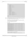
Step 1: Make sure that MLNX_OFED is installed.
Step 2: Verify that the field link_layer is “Ethernet”
# ibv_devinfo
hca_id: mlx4_0
transport:
fw_ver:
node_guid:
sys_image_guid:
vendor_id:
vendor_part_id:
hw_ver:
8
Mellanox Technologies
InfiniBand (0)
2.30.8000
0002:c903:00ef:f4a0
0002:c903:00ef:f4a3
0x02c9
4099
0x1
Running RoCE Over L2 Network Enabled with PFC Application Guide
board_id:
phys_port_cnt:
port:
port:
Rev. 1.5
MT_1090120019
2
1
state:
max_mtu:
active_mtu:
sm_lid:
port_lid:
port_lmc:
link_layer:
PORT_ACTIVE (4)
4096 (5)
1024 (3)
0
0
0x00
Ethernet
2
state:
max_mtu:
active_mtu:
sm_lid:
port_lid:
port_lmc:
link_layer:
PORT_ACTIVE (4)
4096 (5)
4096 (5)
4
3
0x00
InfiniBand
If it is InfiniBand, then run connectx_port_config to change the ports
designation to Ethernet.
Step 3: Configure the IP address of the interface so that the link becomes active.
All InfiniBand verb applications running over InfiniBand verbs must work on RoCE
links if they use GRH headers (if the use of GRH is specified in the address vector).
1.4
Transport Modes
RDMA encapsulated in an Ethernet frame can be configured as 802.1qq tagged or untagged.
Global pause and PFC cannot run together on the same host. If running one server with two
adapter cards, each with 2 ports – all ports work in PFC or global pause.
PFC and global configuration may mislead. If PFC is enabled, global pause does not work
even though it could also be enabled. To make sure global pause is working, make sure PFC is
disabled and global pause is enabled.
Unlike PFC, global pause is cannot be configured globally.
Table 2: PFC/Global Pause Configuration Relation
PFC Configuration
Global Pause
Status
Enabled per host
Enabled per interface (e.g. eth1)
PFC operates on all VLAN interfaces
Enabled per host
Disabled on all interfaces
PFC operates on all VLAN interfaces
Disabled per host
Enabled per interface (e.g. eth1)
Global pause operates on the enabled
interface (eth1). PFC does not operate.
Note: This is the default configuration for
all Ethernet interfaces.
Disabled per host
Disabled on all interfaces
Neither global pause nor PFC operate.
9
Mellanox Technologies
Rev. 1.5
1.4.1
Overview
Untagged Ethernet
In case of untagged Ethernet frames (without a VLAN), the port should be enabled with global
pause flow-control.
Verify that /sys/module/mlx4_en/parameters/pfctx and pfcrx are set to 0 to
enable global pause.
To enable or disable global pause, run:
# ethtool -A eth<x> [rx on|off] [tx on|off]
//For example:
# ethtool –A eth1 rx on tx on
To check the global pause status, run:
# ethtool -a eth<x>
//For example:
# ethtool –a eth1
Pause parameters for eth1:
Autonegotiate:
RX:
TX:
#
1.4.2
off
on
on
802.1Q VLANs
Tagged Ethernet frames carry a 3-bit priority field. The value of this field is derived from the
InfiniBand Service Level (SL) field by taking the 3 least significant bits of the SL field (4 bits).
For RoCE traffic to use VLAN tagged frames, you need to specify the GID table entries that
are derived from the VLAN devices when creating address vectors.
If the interface is configured to work with 802.1q VLAN tags, it is possible to enable
flow-control either with global pause, or with PFC.
To configure a VLAN interface:
Step 1: Verify VLAN support is enabled by the kernel. Usually this requires loading the
802.1q module. Run:
# modprobe 8021q
Step 2: Add a VLAN device (PFC cannot be used when using an interface without VLAN).
Run:
# vconfig add [interface name] [vlan id]
// For example: # vconfig add eth1 100
Step 3: Assign an IP address to the VLAN interface. This creates a new entry in the GID
table (as index 1).
# ifconfig [interface name].[vlan id] [ip]/[netmask]
// For example: # ifconfig eth1.100 10.10.10.10/24 up
Step 4: For rdma_cm applications, specify only the IP address of a VLAN device in order
for the traffic to go with the VLAN tagged frames.
10
Mellanox Technologies
Running RoCE Over L2 Network Enabled with PFC Application Guide
Rev. 1.5
To configure the mlx4_en Ethernet driver to support PFC:
Priority-based Flow Control policy on TX and RX [7:0]. The parameters of mlx4_en:
pfctx – PFC policy on TX[7:0]. Per priority bit mask (default is 0).
pfcrx – PFC policy on RX[7:0]. Per priority bit mask (default is 0).
Each bit of the pfctx and pfcrx represents a priority level (0..7).
To turn on PFC on priority 0, use 0x1, to turn on PFC on priority 1 use 0x2, to turn on
PFC on all priorities use 0xff.
Step 1: Change the values of pfctx and pfcrx in the line below in the file
/etc/modprobe.d/mlx4_en.conf (create the file if it does not exist),
options mlx4_en pfctx=0x08 pfcrx=0x08
Step 2: Restart the network driver. Run:
#/etc/init.d/openibd restart
To show the value of the PFC parameters in the driver, run:
# RX=`cat /sys/module/mlx4_en/parameters/pfcrx`;printf "0x%x\n" $RX
0x8
# TX=`cat /sys/module/mlx4_en/parameters/pfctx`;printf "0x%x\n" $TX
0x8
The values of pfctx and pfcrx should be set according to the priority you need the flow
control to have.
1.5
Priority Mapping
There are two ways to map the kernel priority (skb_prio) to the user priority (UP) that is
attached to the VLAN tag on the Ethernet frame.
1. RoCE traffic priority mapping – kernel bypass
2. TCP/IP traffic priority mapping
Both mapping are required in case there are two flows from the host.
Map SKB priority to user priority
Step 1: Map SKB priority to User priority (UP) for RoCE applications.
16 SKB priority values are available and each is mapped to a single value in the
range of 0-7.
This command will be applied for all ROCE traffic for all VLANs configured on the
host.
For example:
# tc_wrap.py -i eth1 -u 0,1,2,3,4,5,6,7,0,1,2,3,4,5,6,7
Therefore, to map all SKB priorities to a specific egress VLAN priority (e.g. 3):
# tc_wrap.py -i eth1 -u 3,3,3,3,3,3,3,3,3,3,3,3,3,3,3,3
UP 0
UP 1
11
Mellanox Technologies
Rev. 1.5
Overview
UP
UP
2
3
skprio:
skprio:
skprio:
skprio:
skprio:
skprio:
skprio:
skprio:
skprio:
skprio:
skprio:
skprio:
skprio:
skprio:
skprio:
skprio:
skprio:
skprio:
skprio:
skprio:
skprio:
skprio:
skprio:
skprio:
UP
UP
UP
UP
#
0
1
2 (tos:
3
4 (tos:
5
6 (tos:
7
8
9
10
11
12
13
14
15
0 (vlan
1 (vlan
2 (vlan
3 (vlan
4 (vlan
5 (vlan
6 (vlan
7 (vlan
8)
24)
16)
100)
100)
100 tos: 8)
100)
100 tos: 24)
100)
100 tos: 16)
100)
4
5
6
7
Step 2: For TCP/IP application, map the user priority to the VLAN priority egress from the
device using the command vconfig set_egress_map (vconfig set_egress_map
[vlan-device] [skb-priority] [vlan-qos]).
The outbound packets with a particular SKB priority are tagged with a particular
VLAN priority. The default VLAN priority is 0.
This command is applied to specific VLAN.
For example:
# for i in {0..7}; do vconfig set_egress_map eth1.100 $i 3 ; done
Set egress mapping on device -:eth1.100:- Should be visible in
/proc/net/vlan/eth1.100
Set egress mapping on device -:eth1.100:- Should be visible in
/proc/net/vlan/eth1.100
Set egress mapping on device -:eth1.100:- Should be visible in
/proc/net/vlan/eth1.100
Set egress mapping on device -:eth1.100:- Should be visible in
/proc/net/vlan/eth1.100
Set egress mapping on device -:eth1.100:- Should be visible in
/proc/net/vlan/eth1.100
Set egress mapping on device -:eth1.100:- Should be visible in
/proc/net/vlan/eth1.100
Set egress mapping on device -:eth1.100:- Should be visible in
/proc/net/vlan/eth1.100
Set egress mapping on device -:eth1.100:- Should be visible in
/proc/net/vlan/eth1.100
#
To verify the configuration, run (see in boldface):
# cat /proc/net/vlan/eth1.100
Eth1.100 VID: 100
REORDER_HDR: 1
12
Mellanox Technologies
dev->priv_flags: 1
Running RoCE Over L2 Network Enabled with PFC Application Guide
Rev. 1.5
total frames received
total bytes received
Broadcast/Multicast Rcvd
0
0
0
total frames transmitted
total bytes transmitted
total headroom inc
total encap on xmit
Device: eth4
INGRESS priority mappings: 0:0
6
468
0
0
1:0
2:0
3:0
4:0
5:0
6:0 7:0
EGRESS priority mappings: 0:3 1:3 2:3 3:3 4:3 5:3 6:3 7:3
#
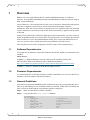
1.5.1
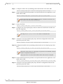
Developing RDMA Applications
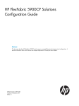
The application rdma_cm must choose a value for IP TOS according to the desired TC and call
the rdma_set_option (id, RDMA_OPTION_ID, RDMA_OPTION_ID_TOS, &tos, sizeof tos)
method.
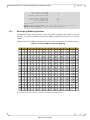
Maping of IP ToS to SKB priority (kernel priority) is static and cannot be modified by the user.
Figure 1: IP ToS to SKB Priority Static Mapping
ToS Prio ToS Prio ToS Prio ToS Prio ToS Prio ToS Prio ToS Prio ToS Prio ToS Prio ToS Prio
0
0 26
4 52
6 78
2 104
2 130
1 156
4 182
6 208
6 234
2
1
0 27
4 53
6 79
2 105
2 131
1 157
4 183
6 209
6 235
2
2
1 28
4 54
6 80
6 106
2 132
0 158
4 184
4 210
6 236
2
3
1 29
4 55
6 81
6 107
2 133
0 159
4 185
4 211
6 237
2
4
0 30
4 56
4 82
6 108
2 134
0 160
0 186
4 212
6 238
2
5
0 31
4 57
4 83
6 109
2 135
0 161
0 187
4 213
6 239
2
6
0 32
0 58
4 84
6 110
2 136
2 162
1 188
4 214
6 240
6
7
0 33
0 59
4 85
6 111
2 137
2 163
1 189
4 215
6 241
6
8
2 34
1 60
4 86
6 112
6 138
2 164
0 190
4 216
4 242
6
9
2 35
1 61
4 87
6 113
6 139
2 165
0 191
4 217
4 243
6
10
2 36
0 62
4 88
4 114
6 140
2 166
0 192
0 218
4 244
6
11
2 37
0 63
4 89
4 115
6 141
2 167
0 193
0 219
4 245
6
12
2 38
0 64
0 90
4 116
6 142
2 168
2 194
1 220
4 246
6
13
2 39
0 65
0 91
4 117
6 143
2 169
2 195
1 221
4 247
6
14
2 40
2 66
1 92
4 118
6 144
6 170
2 196
0 222
4 248
4
15
2 41
2 67
1 93
4 119
6 145
6 171
2 197
0 223
4 249
4
16
6 42
2 68
0 94
4 120
4 146
6 172
2 198
0 224
0 250
4
17
6 43
2 69
0 95
4 121
4 147
6 173
2 199
0 225
0 251
4
18
6 44
2 70
0 96
0 122
4 148
6 174
2 200
2 226
1 252
4
19
6 45
2 71
0 97
0 123
4 149
6 175
2 201
2 227
1 253
4
20
6 46
2 72
2 98
1 124
4 150
6 176
6 202
2 228
0 254
4
21
6 47
2 73
2 99
1 125
4 151
6 177
6 203
2 229
0 255
4
22
6 48
6 74
2 100
0 126
4 152
4 178
6 204
2 230
0
23
6 49
6 75
2 101
0 127
4 153
4 179
6 205
2 231
0
24
4 50
6 76
2 102
0 128
0 154
4 180
6 206
2 232
2
25
4 51
6 77
2 103
0 129
0 155
4 181
6 207
2 233
2
Refer to the MLNX_OFED User Manual for additional information.
13
Mellanox Technologies
Rev. 1.5
1.6
Overview
Performance
To verify RoCE is working and performed as expected run a benchmark test such as
ib_write_bw or any other test.
To run ib_write_bw, run the following on the server side:
# ib_write_bw
//For example
# ib_write_bw -d mlx4_0 -i 1 -R --report_gbits
And the following command on the client side:
# ib_write_bw <server-name>
//For example
#ib_write_bw 11.11.0.1 -R -d mlx4_0 --report_gbits
------------------------------------------------------------------------------RDMA_Write BW Test
Dual-port
: OFF
Device
: mlx4_0
Number of qps
: 1
Transport type : IB
Connection type : RC
Using SRQ
: OFF
TX depth
: 128
CQ Moderation
: 100
Mtu
: 1024[B]
Link type
: Ethernet
Gid index
: 0
Max inline data : 0[B]
rdma_cm QPs
: ON
Data ex. method : rdma_cm
------------------------------------------------------------------------------local address: LID 0000 QPN 0x05a8 PSN 0x8bf4f2
GID: 254:128:00:00:00:00:00:00:246:82:20:255:254:23:31:225
remote address: LID 0000 QPN 0x059f PSN 0x42dea9
GID: 254:128:00:00:00:00:00:00:246:82:20:255:254:23:27:129
------------------------------------------------------------------------------#bytes
#iterations
BW peak[Gb/sec]
BW average[Gb/sec]
MsgRate[Mpps]
65536
5000
36.58
36.58
0.069764
------------------------------------------------------------------------------- #
For additional information on this command and other performance commands, refer to the
Performance Tuning guide on Mellanox.com located at:
http://www.mellanox.com/page/products_dyn?product_family=27&mtag=linux_driver
Additional options to test RoCE is via ibv_rc_pingpong command:
To run ibv_rc_pingpong run the following on the server side:
# ibv_rc_pingpong [options]
//For example
# ibv_rc_pingpong -d mlx4_0 -i 1 -g 0
And the following command on the client side:
# ibv_rc_pingpong [options] <server-name>
//For example
# ibv_rc_pingpong -d mlx4_0 -i 1
-p 20000 -g 0 reg-r-vrt-001
local address: LID 0x0000, QPN 0x0005af, PSN 0xcb5e18, GID
fe80::f652:14ff:fe17:1fe1
remote address: LID 0x0000, QPN 0x0005a3, PSN 0x86a929, GID fe80::f652:14ff:fe17:1b81
8192000 bytes in 0.01 seconds = 10400.89 Mbit/sec
1000 iters in 0.01 seconds = 6.30 usec/iter
#
For additional information, refer to Performance Tuning Guidelines on Mellanox.com.
14
Mellanox Technologies
Running RoCE Over L2 Network Enabled with PFC Application Guide
1.7
Rev. 1.5
Port Statistics
It is possible to read port statistics in the same manner as regular InfiniBand ports. The
information is available from the sysfs at /sys/class/infiniband/<device>/
ports/<port number>/counters.
The supported counters are:
port_rcv_packets
port_xmit_packets
port_rcv_data
port_xmit_data
These counters count only InfiniBand data and are not account for Ethernet traffic.
To read the number of transmitted packets, run:
# cat /sys/class/infiniband/<dev>/ports/<port>/counters/port_xmit_packets
//for example
# cat /sys/class/infiniband/mlx4_0/ports/1/counters/port_xmit_packets
1740380
#
RoCE traffic is not shown in the associated Etherent device's counters since it is offloaded
by the hardware and does not go through Ethernet network driver.
1.8
DCBX Consideration
It is possible to turn on LLDP with DCBX TLVs for auto PFC configuration from the switch to
the host. To do that the LLDP protocol should be turned on, on the switch and on the host, in
addition DCBX TLVs should be enabled on both switch and host.
15
Mellanox Technologies
Rev. 1.5
2
RoCE and PFC Example Setup
RoCE and PFC Example Setup
The objective of the example in this chapter is to run RoCE over L2 with PFC enabled.
(This example configured PFC with priority 3 enabled).
Note: the solution in this chapter is described and discussed in Mellanox Community –
Solutions space.
http://community.mellanox.com/docs/DOC-1414
More enhanced solution for RoCE (lossless) and TCP (lossy) flows configured over L2
Ethernet network enabled with PFC can be found in this link:
http://community.mellanox.com/docs/DOC-1415
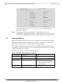
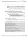
2.1
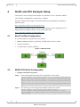
Best Test-Bed Configuration
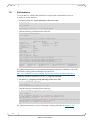
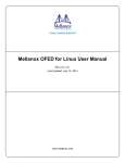
It is recommended to set up the network as follows:
Mellanox Ethernet switch (e.g. SX1036) , MLNX-OS® version 3.3.4304
3x Hosts, OS RH6.4
3x ConnectX®-3, MLNX_OFED 2.1
Figure 2: Network Setup
2.2
MLNX-OS Switch Configuration
Configure the SX1036 as follows:
Step 1: Create and configure the required VLAN interface on the switch
switch
switch
all
switch
all
switch
all
(config) # interface ethernet 1/1-1/3 switchport mode hybrid
(config) # interface ethernet 1/1 switchport hybrid allowed-vlan
(config) # interface ethernet 1/2 switchport hybrid allowed-vlan
(config) # interface ethernet 1/3 switchport hybrid allowed-vlan
Step 2: The following switch configuration should be added to the Switch
switch (config) # dcb priority-flow-control enable
switch (config) # dcb priority-flow-control priority 3 enable
switch (config) # interface ethernet 1/1-1/3 dcb priority-flow-control
mode on force
16
Mellanox Technologies
Running RoCE Over L2 Network Enabled with PFC Application Guide
Rev. 1.5
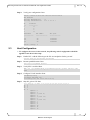
Step 3: Verify your configuration. Run:
switch (config)# show dcb priority-flow-control
PFC enabled
Priority Enabled List
Priority Disabled List
TC
--0
1
2
3
:3
:0 1 2 4 5 6 7
Lossless
---------N
Y
Y
N
Interface
PFC admin
------------------------…
1/1
On
1/2
On
1/3
On
…
switch (config) #
2.3
PFC oper
------------Enabled
Enabled
Enabled
Host Configuration
To configure the servers in the network, the following switch configuration should be
applied to each host in the setup:
Step 1: Enable PFC. Add the following to the file /etc/modprobe.d/mlx4_en.conf:
options mlx4_en pfctx=0x08 pfcrx=0x08
Step 2: Restart openidb daemon. Run:
#/etc/init.d/openibd restart
Step 3: Verify PFC is enabled. Run:
#RX=`cat /sys/module/mlx4_en/parameters/pfcrx`;printf "0x%x\n" $RX
0x08
Step 4: Configure VLAN interface. Run:
# modprobe 8021q
# vconfig add eth1 100
# ifconfig eth1.100 11.11.100.1/24 up
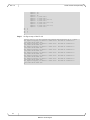
Step 5: Map skb_prio to UP. Run:
# tc_wrap.py -i
UP 0
UP 1
UP 2
UP 3
skprio:
skprio:
skprio:
skprio:
skprio:
skprio:
skprio:
skprio:
skprio:
skprio:
skprio:
skprio:
skprio:
eth1 -u 3,3,3,3,3,3,3,3,3,3,3,3,3,3,3,3
0
1
2 (tos: 8)
3
4 (tos: 24)
5
6 (tos: 16)
7
8
9
10
11
12
17
Mellanox Technologies
Rev. 1.5
RoCE and PFC Example Setup
skprio:
skprio:
skprio:
skprio:
skprio:
skprio:
skprio:
skprio:
skprio:
skprio:
skprio:
UP
UP
UP
UP
#
13
14
15
0 (vlan
1 (vlan
2 (vlan
3 (vlan
4 (vlan
5 (vlan
6 (vlan
7 (vlan
100)
100)
100 tos: 8)
100)
100 tos: 24)
100)
100 tos: 16)
100)
4
5
6
7
Step 6: Set Egress map of the VLAN
# for i in {0..7}; do vconfig set_egress_map eth1.100 $i 3 ; done
Set egress mapping on device -:eth1.100:- Should be visible in
/proc/net/vlan/eth1.100
Set egress mapping on device -:eth1.100:- Should be visible in
/proc/net/vlan/eth1.100
Set egress mapping on device -:eth1.100:- Should be visible in
/proc/net/vlan/eth1.100
Set egress mapping on device -:eth1.100:- Should be visible in
/proc/net/vlan/eth1.100
Set egress mapping on device -:eth1.100:- Should be visible in
/proc/net/vlan/eth1.100
Set egress mapping on device -:eth1.100:- Should be visible in
/proc/net/vlan/eth1.100
Set egress mapping on device -:eth1.100:- Should be visible in
/proc/net/vlan/eth1.100
Set egress mapping on device -:eth1.100:- Should be visible in
/proc/net/vlan/eth1.100
#
18
Mellanox Technologies
Running RoCE Over L2 Network Enabled with PFC Application Guide
2.4
Verification Procedures
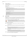
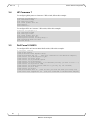
2.4.1
Network Protocol – ICMP
Rev. 1.5
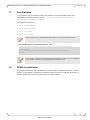
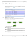
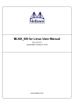
A basic sanity test would be to ping two servers and see that the ping (ICMP) is running over
the desired priority on the network. In Figure 3 you can see the ICMP packets carrying VLAN
100 and priority bit 3.
Figure 3: ICMP Packets
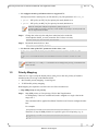
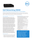
2.4.2
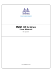
RoCE Performance Verification
To test that RoCE is running over the configuration setup. Direct RoCE traffic from two
servers (S2 and S3) directed to one server (S1).
Figure 4: RoCE Test Setup
Run the following performance tests:
Step 1: On host S1, run:
# ib_write_bw -R --report_gbits --port=12500 -D 10 & ib_write_bw -R
--report_gbits --port=12510 -D 10
Step 2: On host S2, run:
# ib_write_bw -R --report_gbits 11.11.100.1
--port=12500 -D 10
Step 3: On host S3, run:
# ib_write_bw -R --report_gbits 11.11.100.1
--port=12510 -D 10
19
Mellanox Technologies
Rev. 1.5
2.4.3
RoCE and PFC Example Setup
Port Priority Counters
Check host port priority counters (traffic and pause counters – in boldface):
# ethtool -S eth1 | grep prio_3
rx_prio_3_packets: 5152
rx_prio_3_bytes: 424080
tx_prio_3_packets: 328209
tx_prio_3_bytes: 361752914
rx_pause_prio_3: 14812
rx_pause_duration_prio_3: 0
rx_pause_transition_prio_3: 0
tx_pause_prio_3: 0
tx_pause_duration_prio_3: 47848
tx_pause_transition_prio_3: 7406
#
Check switch port priority counters (traffic and pause counters – in boldface):
# show interfaces ethernet 1/1 counters priority 3
Rx
333364
packets
333364
unicast packets
0
multicast packets
0
broadcast packets
362177148
bytes
14814
pause packets
49168
pause duration seconds
Tx
333371
packets
333362
unicast packets
6
multicast packets
3
broadcast packets
368845148
bytes
0
pause packets
#
20
Mellanox Technologies
Running RoCE Over L2 Network Enabled with PFC Application Guide
3
Various Switch Configuration
3.1
Mellanox SwitchX® Based Systems
Rev. 1.5
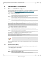
The flow below describes how to configure PFC or global pause on Mellanox systems based
MLNX-OS® (refer to http://www.mellanox.com/page/ethernet_switch_overview).
To configure PFC on SwitchX based systems:
Step 1: Enable PFC globally. Run:
switch (config) # dcb priority-flow-control enable
Step 2: Enable specific priority on the switch (all ports). Run:
switch (config) # dcb priority-flow-control priority <level> enable
Step 3: Enable specific PFC on specific interface. Run:
switch (config interface ethernet 1/1) # dcb priority-flow-control mode
on force
The following is an example for how to configure PFC enabled on port 1/1 for priority 3:
switch
switch
switch
switch
(config)
(config)
(config)
(config)
# dcb priority-flow-control enable
# dcb priority-flow-control priority 3 enable
# interface ethernet 1/1 dcb priority-flow-control mode on force
#
To configure global pause on SwitchX based systems:
Step 1: Enable global pause per interface (receive). Run:
switch (config interface ethernet 1/1) # flowcontrol receive on
Step 2: Enable global pause per interface (send). Run:
switch (config interface ethernet 1/1) # flowcontrol send on
The following is an example for how to configure global pause on port 1/1:
switch
switch
switch
switch
(config) # interface ethernet 1/1
(config interface ethernet 1/1) # flowcontrol receive on
(config interface ethernet 1/1) # flowcontrol send on
(config interface ethernet 1/1) #
PFC and Flow Control features cannot be configured together on the same interface.
Refer to the Ethernet Quality of Service (QoS) section of the MLNX-OS User Manual for more
information.
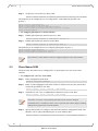
3.2
Arista Switches (EoS)
The flow below describes how to configure PFC or global pause on Arista switches via EoS.
To configure PFC on Arista switches:
Step 1: Set DCBX mode. Run:
switch (config-if-Et10) # dcbx mode ieee
Step 2: Enable PFC on specific interface. Run:
switch (config-if-Et10) # priority-flow-control mode on
21
Mellanox Technologies
Rev. 1.5
Various Switch Configuration
Step 3: Set priority X as lossless (no drop). Run:
switch (config-if-Et10) # priority-flow-control priority <X> no-drop
The following is an example for how to configure PFC with enabled on port Et10 for
priority 3:
switch
switch
switch
switch
switch
(config) # interface et1
(config-if-Et1)# dcbx mode ieee
(config-if-Et1)# priority-flow-control mode on
(config-if-Et1)# priority-flow-control priority 3 no-drop
(config-if-Et1)#
To configure global pause on Arista switches:
Step 1: Enable global pause per interface (receive). Run:
switch (config-if-Et10) # flowcontrol receive on
Step 2: Enable global pause per interface (send). Run:
switch (config-if-Et10) # flowcontrol send on
The following is an example for how to configure global pause on port 1/1:
switch (config) # interface et10
switch (config-if-Et10)# flowcontrol receive on
switch (config-if-Et10)# flowcontrol send on
PFC and Flow Control features cannot be configured together on the same interface.
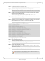
3.3
Cisco Nexus 5020
The flow below describes how to configure PFC or global pause on Cisco Nexus 5020
switches.
To configure PFC on Cisco Nexus 5020:
Step 1: Enter configuration mode. Run:
switch # configure terminal
Step 2: Enter VLAN configuration sub-mode. If the VLAN does not exist, the system first
creates the specified VLAN. Run:
switch (config) # vlan {vlan-id | vlan-range}
Step 3: Name the VLAN. Up to 32 alphanumeric characters may be used. Run:
switch (config) # vlan {vlan-id | vlan-range}
The names of VLAN1 or the internally allocated VLANs cannot be changed.
The default value is VLANxxxx where “xxxx” represents four numeric digits (including
leading zeroes) equal to the VLAN ID number.
Step 4: Specify the interface to configure, and enters the interface configuration mode. The
interface can be a physical Ethernet port or a port channel. Run:
switch (config) # interface {type slot/port | port-channel number}
22
Mellanox Technologies
Running RoCE Over L2 Network Enabled with PFC Application Guide
Rev. 1.5
Step 5: Configure the interface as a trunk port. Run:
switch (config-if) # switchport mode trunk
Step 6: (Optional) Configure necessary parameters for a trunk port. Run:
switch(config-if)# switchport trunk {allowed vlan vlan-id | native vlan
vlan-id}
Step 7: Set PFC mode for the selected interface. Specify auto to negotiate PFC capability.
Specify on to force-enable PFC. Run:
switch(config-if)# priority-flow-control mode {auto | on }
Step 8: (Optional) Enable IEEE 802.3x link-level flow control for the selected interface. Set
receive and/or transmit on or off. Run:
switch(config-if)# flowcontrol [receive {on|off}] [transmit {on|off}]
Step 9: Enable the VLAN. The default value is no shutdown (or enabled). You cannot shut
down the default VLAN, VLAN1, or VLANs 1006 to 4094. Run:
switch(config-vlan)# no shutdown
The following is an example for how to configure two ports:
switch
switch
switch
switch
switch
switch
switch
switch
switch
switch
switch
switch
switch
switch
switch
switch
switch
# configure terminal
(config) # vlan 50
(config-vlan) # name roce
(config) # interface ethernet 1/3
(config-if) # switchport mode trunk
(config-if) # switchport trunk allowed vlan 50
(config-if) # priority-flow-control mode on
(config-if) # flowcontrol receive on transmit on
(config-vlan) # state active
(config-vlan) # no shutdown
(config) # interface ethernet 1/11
(config-if) # switchport mode trunk
(config-if) # switchport trunk allowed vlan 50
(config-if) # priority-flow-control mode on
(config-if) # flowcontrol receive on transmit on
(config-vlan) # state active
(config-vlan) # no shutdown
To configure global pause on Cisco Nexus 5020:
Step 1: Enter configuration mode. Run:
switch # configure terminal
Step 2: Create the MAC ACL and enter ACL configuration mode. Run:
switch (config) # mac access-list name
Step 3: Creates a rule in the MAC ACL. Run:
switch (config-mac-acl) # [sequence-number] {permit | deny} source
destination protocol
Step 4: Create a named object that represents a class of traffic. Run:
switch (config) # class-map type qos class-name
Class-map names can contain alphabetic, hyphen, or underscore characters, are
case sensitive, and can be up to 40 characters.
23
Mellanox Technologies
Rev. 1.5
Various Switch Configuration
Step 5: Configure a traffic class by matching packets based on the ACL name. Run:
switch (config-cmap-qos) # match access-group name acl-name
Step 6: Create a named object that represents a set of policies that are to be applied to a set of
traffic classes. Run:
switch (config-cmap-qos) # policy-map type qos policy-name
Policy-map names can contain alphabetic, hyphen, or underscore characters, are
case sensitive, and can be up to 40 characters.
Step 7: Create class, Run:
switch (config-cmap-qos) # class class-name
Step 8: Configure one or more QOS group values to match for classification of traffic into
this class map. Run:
switch (config-pmap-c-qos) # set qos-group qos-group-value
The range of qos-group-value is 2-5. There is no default value.
Step 9: Associate a class map with the policy map, and enter configuration mode for the
specified system class. Run:
switch (config) # class [type {network-qos}] class-name
Step 10: Configure the traffic class by matching packets based on a list of QoS group values.
Run:
switch (config-cmap-nq) # match qos-group qos-group-value
QOS group values range: 0-5. QoS group 0 is equivalent to class-default, and QoS
group 1 is equivalent to class-fcoe.
QoS groups 0 and 1 are reserved for default classes and cannot be configured.
Step 11: Create a named object that represents a set of policies that are to be applied to a set of
traffic classes. Run:
switch (config-cmap-nq) # policy-map [type {network-qos}] policy-name
Step 12: Associate a class map with the policy map, and enters configuration mode for the
specified system class. Run:
switch(config-cmap-nq) # class type network-qos class-name
24
Mellanox Technologies
Running RoCE Over L2 Network Enabled with PFC Application Guide
Rev. 1.5
Step 13: Configure a no-drop class. Run:
switch (config-pmap-nq-c) # pause no-drop [pfc-cos pfc-cos-value]
If no parameter is specified, the default policy is drop. The range of
pfc-cos-value: 0-7. This option is supported only for an ACL-based system
class.
The drop policy is a simple tail drop where arriving packets are dropped if the
queue goes over its allocated size.
Step 14: Enter system class configuration mode. Run:
switch (config) # system qos
Step 15: Specify the policy map to use as the service policy for the system. Run:
switch (config-sys-qos) # service-policy type qos input policy-name
policy-map configuration has three modes:
network-qos - network-wide (system QoS) mode
qos – classification mode (system QoS input or interface input only)
queuing - queuing mode (input and output at system QoS and interface)
Step 16: Create a policy. Run:
switch (config-sys-qos)# service-policy type network-qos policy-name
Step 17: Specify the interface to be changed. Run:
switch (config)# interface type slot/port
Step 18: Enables LLC for the selected interface. Set receive and/or transmit on or off. Run:
flowcontrol [receive {on | off}] [transmit {on | off}]
This example tags all traffic as lossless:
switch# configure terminal
switch(config)# mac access-list test
switch(config-mac-acl)# 10 permit any any
!
switch(config)# class-map type qos test1
switch(config-cmap-qos)# match access-group name test
switch(config-cmap-qos)# policy-map type qos test1
switch(config-cmap-qos)# class test1
switch(config-pmap-c-qos)# set qos-group 4
!
switch(config)# class-map type network-qos test1
switch(config-cmap-nq)# match qos-group 4
switch(config-cmap-nq)# policy-map type network-qos test1
switch(config-cmap-nq)# class type network-qos test1
switch(config-pmap-nq-c)# pause no-drop
!
switch(config)# system qos
switch(config-sys-qos)# service-policy type qos input test1
switch(config-sys-qos)# service-policy type network-qos test1
!
switch(config)# interface ethernet 1/2
switch(config-if)# flowcontrol receive on transmit on
25
Mellanox Technologies
Rev. 1.5
3.4
Various Switch Configuration
HP Comware 7
To configure global pause on Comware 7 HP switch, follow this example:
interface FortyGigE2/0/7
port link-mode bridge
port link-type trunk
port trunk permit vlan all
flow-control
flow-interval 5
To configure PFC on Comware 7 HP switch, follow this example:
interface FortyGigE2/0/6
port link-mode bridge
port link-type trunk
port trunk permit vlan all
priority-flow-control auto
priority-flow-control no-drop dot1p 3
lldp tlv-enable dot1-tlv dcbx
qos trust dot1p
3.5
Dell Force10 S4810
To configure PFC on Force10 S4810 Dell switch, follow this example:
# configure terminal
(conf)# dcb enable
(conf)# service-class dynamic dot1p
(conf)# interface ten 1/1
{the port connected to the Mellanox adapter}
(conf-if-ten 1/1)# description to_NIC
(conf-if-ten 1/1)# mtu 12000
(conf-if-ten 1/1)# portmode hybrid
(conf-if-ten 1/1)# switchport
(conf-if-ten 1/1)# pfc priority 3 {or whatever priority you want to use 0 - 7}
(conf-if-ten 1/1)# protocol lldp
(conf-if-ten 1/1)# dcbx version ieee-v2.5 {you may try cee instead}
(conf-if-ten 1/1)# no shut
(conf-if-ten 1/1)# exit
(conf)# interface vlan 10 {vlan ID that you have the RoCE port setup for}
(conf-if-vl-10)# tagged ten 1/1 {the port connected to the Mellanox adapter}
26
Mellanox Technologies