1
FL1E
LONWORKS®
AS-Interface
http://smart.idec.com
(100617)
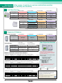
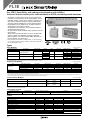
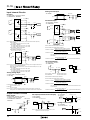
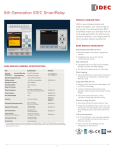
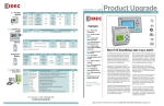
FL1E IDEC SmartRelay
FL1E
Small LCD panel supports 10 languages
Scrollable messages and characters of various languages
provide more flexibility.
• English, Japanese, Chinese (GB-2312), German, French,
Italian, Turkish, Dutch, and Russian characters available
• Backlight time can be set.
• Adjustable contrast
• 50 screens with a maximum of 48 characters per screen can
be displayed.
Digital/Analog Input
Eight digital inputs: 4 high-speed digital (I3 to I6) with up to
5 kHz response frequency and 4 digital/analog compatible
(I1, I2, I7, I8)
(Applicable models: FL1E-H12RCE/FL1E-B12RCE/FL1E-H12SND)
Control Buttons
Easy programming using 6 buttons. No tools necessary for
changing parameters even while mounted on a panel.
Multi-function Interfaces
A memory cartridge stores a user program and the communication cable for WindLGC can be installed/removed easily,
allowing for an easy system changeover.
New cartridges to suit a range of different
applications
NPN/PNP Sensor Input
Output from NPN/PNP sensors can be inputted without
external resistance. This enables a wider selection of input
devices, saving wiring time.
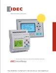
Memory cartridge (FL1E-PM4)
Digital Output
Battery cartridge (FL1E-PB1)
Stores a user program. Equipped with a protection function to prevent unauthorized program
changes or copying.
(Applicable models: FL1E-H12RCA/FL1E-B12RCA/FL1B-M08D2R2)
Use outputs for controlling lights, small motors, and solenoid
valves up to 10A.
Extends the data backup life up to 2 years.
Memory/battery cartridge (FL1E-PG1)
Has both memory and battery functions.
Expandability
Can be combined with FL1B expansion I/O modules and communication modules, and an FL1D analog output module for system
configuration.
Program Size
WindLGC Ver. 6.*
Programming software for the FL1E is upgraded to WindLGC Ver. 6.*.
WindLGC is upgraded not only for easier programming, but also for
more convenience in debugging.
Download Demo Version
Large (3,800 bytes maximum) program size allows for easy programming using function blocks, without a concern for program
size (within the programmable bytes).
Program
Size
No. of Programmable Blocks
Message
Display
Bar
Graph
Internal
Marker
REM
Relays/
Timers
3,800 bytes
200
50
32
27
250
Unlimited
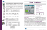
New Funcion Blocks (3 types)
Analog math is enhanced by combining function blocks that process analog signals, providing a variety of applications.
http://www.idec.com/download
Upward Compatible
User Program
User programs for the preceding FL1A, FL1B, FL1C, and FL1D IDEC
SmartRelays can be imported to the FL1E using WindLGC Ver. 6.* and
the memory cartridge.
See page 4.
2
(100617)
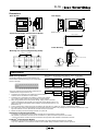
Concept
Replaces relays, timers, and counters
The FL1E IDEC SmartRelay contains various functions such as timers, counters, and a
calendar. No complicated wiring is required. Just use the buttons and the LCD panel to write
programs. System changeover that requires parameter changes can be completed easily.
Smaller system than using a PLC
Sensor
Reduces your workload
Display
PLC
Cou
nter
Relay Terminal
Ana
Motor
Time
r
log
Rela
y
Solenoid Valve
Change your complicated system of multiple
relays, timers, and counters to a single IDEC
SmartRelay.
The IDEC SmartRelay replaces many functions of
peripheral equipment of the programmable logic
controller. Features 10A max. output contacts and
up to 48 display characters.
39 different types of function blocks make it
possible to perform various control operations
easily.
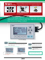
Easy-to-see display with more variety of characters and graphs.
Advanced control is made possible with PWM and analog math.
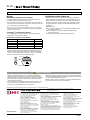
Easy-to-use text display is added!
FL1E Text Display
FL1E Text Display
The messages on the LCD panel of the base module can be seen clearly
on the new panel-mount text display. Wide-size LCD screen (61.0 × 33.0
mm) and large control buttons provide excellent visibility and ease of
operation. IP65 protection.
Wide-size text display improves operability.
Excellent visibility reduces
operation errors.
Note: Programs cannot be edited on
the text display.
(100617)
Flexible operation, such as on-site
parameter changes and monitoring
is made possible.
Four membrane pushbuttons are
provided.
Can be also used for turning on backlight and starting/stopping programs.
Buttons of the same style as the base
module are supplied. Parameter
changes and monitoring screen scroll
can be accomplished.
Programs cannot be edited on the text
display.
The FL1E text display requires the
FL1E base module as a controller.
3
solutions for
engineers!
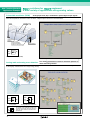
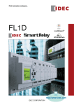
A wide variety of applications using analog values.
New Function Blocks &
Application Examples
Pulse width modulator (PWM)
Analog input value (Ax) is modulated to pulsed digital output signals.
Heater is controlled to maintain the temperature inside a green house.
When the temperature decreases to 20°C and below, a digital output is turned on to start the heater.
Heater
Ventilation Fans
Temperature
Sensors
FL1E Text Display
(FL1E base module
inside the control panel)
En
Ax
Par
Control Panel
Q
Pulse Width Modulator (PWM)
Four analog parameters are used for arithmetic operation to
Analog math and analog error detection obtain the analog solution.
The average value of power used in show rooms A, B, and C is obtained and monitored. If the value exceeds the target value,
a warning sign is illuminated to encourage energy-saving.
En
Par
AQ
Analog Math
En
R
Par
4
Q
En
R
Par
Q
Analog Math Error Detection
The results of four arithmetic operations are
monitored, and digital outputs are turned on
when the value exceeds or falls below the
preset range.
(100617)
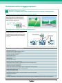
The standard solution for
engineers!
Replaces timers and counters.
Control of equipment and system incorporating various controls is made possible.
Timing control for a water sprinkler and fountain system
The IDEC SmartRelay can replace weekly timers
for controlling the timing of water sprinklers and
fountains. The duration of the water flow can be
changed depending on the hour, and the clock
can be rewritten by using the buttons on the FL1E.
Reducing mounting space and cost.
__ Hr __ Min
FL1E
(outputs
expandable)
Water Sprinkler
Fountain
Data acquisition system of machine operating hours
With an operating hours counter function, the current
counter value can be read on the LCD panel on
the IDEC SmartRelay. One IDEC SmartRelay can
count operating hours of multiple machines, making
it possible to obtain information such as operating
conditions and replacement period of consumable
components.
IDEC SmartRelay
Three systems
Other Application Examples
Cargo lifting equipment
Movement control of patient transfer systems
Automatic ship mast lifting machines
Air shower operating machines
Water sprinkler control
Drainage pump control
Conveyor belts
Ice-cream mixer control
Pipe driver control for PVC greenhouse
Forward/reverse motor rotation monitoring buzzer control, tower light control
Semi-automatic wire cutting machines
Monitoring of machine operating time
Analog sensor disconnection detection device, analog value monitoring device
Control panel temperature, humidity monitoring device
Car park warning light control
IC storage box heater control
Operating time adjustment device for game machines in amusement arcades
Fluid level control device
...and more!
The IDEC SmartRelay is successfully used not only in areas of factory automation but also in various control equipment.
(100617)
5
Wide variety of modules for various combinations provides
for flexibility and versatility.
Base Module &
Expansion Modules
FL1E Base Modules
FL1E-H12SND
FL1E-H12RCE
FL1E-H12RCA
FL1E-H12RCC
Power Voltage
24V DC
12/24V DC
24V AC/DC
100 to 240V AC/DC
Input
DC input: 8 points (PNP)
(Analog 4 points)
DC input: 8 points (PNP)
(Analog 4 points)
AC/DC input: 8 points
(PNP/NPN input)
AC/DC input: 8 points
(PNP input)
Relay output: 4 points
Output
Transistor output: 4 points
Relay output: 4 points
Relay output: 4 points
Programming Function
With
With
With
With
Clock Function
With (Note)
With
With
With
Note: FL1E-H12SND of Ver. 4 and before does not have clock function.
FL1E-B12RCE
FL1E-B12RCA
FL1E-B12RCC
Power Voltage
12/24V DC
24V AC/DC
100 to 240V AC/DC
Input
DC input: 8 points (PNP)
(Analog 4 points)
AC/DC input: 8 points
(PNP/NPN input)
AC/DC input: 8 points
(PNP input)
Output
Relay output: 4 points
Relay output: 4 points
Relay output: 4 points
Programming Function
Without
Without
Without
Clock Function
With
With
With
Initialization Time: After power-up, the FL1E takes a maximum of 10 seconds (when using a memory cartridge or
memory/battery cartridge) or 9 seconds (without using any cartridges or when using a battery
cartridge) for initialization. When initialization is complete, the FL1E is automatically set to RUN mode.
Expansion I/O Modules
Combination I/O Modules
FL1B-M08B1S2
FL1B-M08B2R2
FL1B-M08D2R2
FL1B-M08C2R2
Power Voltage
24V DC
12/24V DC
24V AC/DC
100 to 240V AC/DC
Input
DC input: 4 points
(PNP input)
DC input: 4 points
(PNP input)
AC/DC input: 4 points
(PNP/NPN input)
AC/DC input: 4 points
(PNP input)
Output
Transistor output: 4 points
Relay output: 4 points
Relay output: 4 points
Relay output: 4 points
Max. Expansion Modules
4
4
4
4
FL1B-J2B2
Analog Modules
Analog Input Module
Max. Expansion Modules
FL1D-K2BM2
Analog Output Module
Power Voltage
12/24V DC
24V DC
Analog I/O Points
Analog input: 2 points
Analog output: 2 points
Analog I/O Range
Voltage input: 0-10V DC
Current input: 0-20 mA
Voltage output: 0-10V DC
Current output: 0-20, 4-20 mA
Resolution
10 bits
10 bits
Max. Expansion Modules
4
1
Use of a base module and expansion I/O
modules of the same power voltage rating is recommended, with power supplied to all modules
using one power supply.
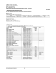
Module Combination and Allocation Numbers
1. Maximum configuration when using a base module without analog inputs
FL1E-H12RCA
FL1B-M08B2R2
FL1B-J2B2
FL1D-K2BM2
Digial Input: I
1 2 3 4 5 6 7 8 9 10 11 12 13 14 15 16 17 18 19 20 21 22 23 24
Analog Input: AI
3 4 5 6 7 8
Analog Output: AQ
1 2
1 2 3 4
5 6 7 8 9 10 11 12 13 14 15 16
Digital Output: Q
Note 1:Digital inputs: 24, analog inputs: 6, digital outputs, 16, analog outputs: 2
Note 2:AI3 to AI8 are allocated to the analog input module.
2. Maximum configuration when using two analog inputs on the base module
FL1E-H12RCE
FL1B-M08B2R2
FL1B-J2B2
FL1D-K2BM2
Digial Input: I
1 2 3 4 5 6 7 8 9 10 11 12 13 14 15 16 17 18 19 20 21 22 23 24
Analog Input: AI
1 2
3 4 5 6 7 8
Analog Output: AQ
1 2
1 2 3 4
5 6 7 8 9 10 11 12 13 14 15 16
Digital Output: Q
Note 1:Digital inputs: 22, analog inputs: 8, digital outputs: 16, analog outputs: 2
Note 2:Analog inputs AI3 and AI4 are allocated to the analog input module.
Note 3:When using two analog inputs on the FL1E base module, allocation of I/O numbers has a compatibility with the
FL1D series.
3. Maximum configuration when using four analog inputs on the base module
FL1E-H12RCE
FL1B-M08B2R2
FL1B-J2B2
FL1D-K2BM2
Digial Input: I
1 2 3 4 5 6 7 8 9 10 11 12 13 14 15 16 17 18 19 20 21 22 23 24
Analog Input: AI
3 4
1 2
5 6 7 8
Analog Output: AQ
1 2
1 2 3 4
5 6 7 8 9 10 11 12 13 14 15 16
Digital Output: Q
Maximum number of connectable modules
per base module:
· 4 combination I/O modules
· 4 analog input modules
· 1 analog output module
Maximum number of I/O points*
Digital input: 24
Digital output: 16
Analog input: 8
Analog output: 2
* The maximum number includes the I/O points
of the base module and the expansion I/O
modules.
Base module
Combination I/O module
Analog input module
Analog output module
For users using analog inputs:
By setting the embedded analog input number using the
WindLGC Ver. 6.*, I/O numbers can be allocated to the
base module and expansion analog module.
Note 1:Digital inputs: 20, analog inputs: 8, digital outputs: 16, analog outputs: 2
Note 2:Using WindLGC Ver. 6.*, allocate AI3 and AI4 to the base module. AI5 to AI8 are allocated to the analog
input module.
6
(100617)
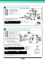
AS-Interface Communication Module FL1B-CAS2
System Configuration Example
The AS-Interface communication
module provides an optimum solution for savings in cables, installation
space, and wiring cost and the possibility for decentralized control.
Open Network
(CC-Link, DeviceNet)
• Virtual I/O points: 4 input points, 4
output points.
• FL1B-CAS2 is compatible with ASInterface Ver. 2.0.
Branch
Connector
PS2R
AS-Interface
Power Supply
SX5A
Safety
Monitor
SX5A
IP20
Manifold Solenoid
Communication Terminal Value
Sensor (AS-Interface
Light Tower
Direct Connection Type)
AS-Interface
Communication Module
Combination and I/O Allocation Examples
SX5A IP67
Communication
Terminal
Sensor
Using expansion I/O modules
FL1E-H12RCE
FL1B-M08B2R2
Light
Curtain
Emergency
Stop Switch
HW/L6 Series
SwitchNet™ Control Units
(AS-Interface Direct
Connection Type)
• When using 4 analog inputs on the base module
Digial Input: I
Analog Input: AI
Digital Output: Q
SX5A
AS-Interface
Gateway
FC4A
AS-Interface
Master Module
AS-Interface Safety at work
FL1B-CAS2
1 2 3 4 5 6 7 8 9 10 11 12
13 14 15 16
3 4
1 2
5 6
1 2 3 4
5 6 7 8
9 10 11 12
Base module
Combination I/O module
AS-Interface communication module
Analog input module
FL1B-J2B2
For SwitchNet® and IDEC
AS-Interface devices, see
catalogs No. EP1143,
EP1043 and EP1025.
Note 1:I/O numbers are automatically allocated starting with the base module.
Note 2:When the base module with analog inputs is used, the subsequent
numbers will be allocated to the analog input modules.
LonWorks® Communication Module FL1B-CL1C12
System Configuration Example
Combination of easy-to-program IDEC
SmartRelay and LonWorks® communication module achieves remote
control and monitoring on a LonWorks® network.
• Max. virtual input points: 16 points
• Max. virtual output points: 12 points
• Max. virtual analog input points: 8
points
Control Server/
Monitor and Operation Terminal
Ethernet
PLC
LONWORKS®
Gateway
Air Conditioner
Remote-control Relay
(Number of I/O points depends on the
combination of modules.)
Control Valve
LONWORKS®
Communication
Module
An external interface file (XIF extension) unique to each
LonWorks® communication module is needed to communicate through the LonWorks® network. The XIF file can
be downloaded from the following website.
Thermometer
Non-LONWORKS®
Device
http://www.idec.com/download
Voltage (analog value)
Current (analog value)
Power
Alarm
Failure
Control
Controller
Illumination
Shade
LONWORKS®
Communication Module
Illumination Meter
SX5L
Communication Terminal (I/O unit)*
Intrusion Detector
SX5L Communication Terminal
(I/O unit)*
* Terminal block type communication terminal: I/O
unit installed with standard network variables (SNVT)
LONWORKS® Network
Module Combination and Allocation Numbers
1. Maximum number of I/O points when using LonWorks® communication module
FL1D-H12RCC
Digial Input: I
Analog Input: AI
Digital Output: Q
FL1B-CL1C12
1 2 3 4 5 6 7 8 9 10 11 12 13 14 15 16 17 18 19 20 21 22 23 24
1 2 3 4 5 6 7 8
1 2 3 4
5 6 7 8 9 10 11 12 13 14 15 16
2. Using expansion I/O module (using 4 analog inputs on the base module)
FL1D-H12RCE
FL1B-M08B2R2
Base module
LonWorks® communication module
Combination I/O module
Analog input module
Analog output module
FL1B-CL1C12
Digial Input: I
1 2 3 4 5 6 7 8 9 10 11 12
13 14 15 16 17 18 19 20 21 22 23 24
Analog Input: AI
3 4
1 2
5 6
7 8
Digital Output: AQ
1 2
Digital Output: Q 1 2 3 4
5 6 7 8
9 10 11 12 13 14 15 16
FL1B-J2B2 FL1D-K2B2
Note 1: One LonWorks® communication module can be used with a base module and must be mounted at the far right end of the row.
Note 2: I/O numbers are automatically allocated starting with the base module.
Note 3: When the base module with analog inputs is used, the subsequent numbers will be allocated to the analog input modules and
LonWorks® communication module.
(100617)
For details about SX5L
LonWorks® communication
terminals, see catalog No.
EP995.
LonMark®, LonWorks®,
LON®, Neuron®, 3120®,
3150®, and Echelon® are
registered trademarks of
Echelon, USA.
7
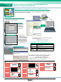
Programming
Software
WindLGC reduces development and debugging time of
simple and complex programming
WindLGC Ver. 6.* Programming Software for IDEC SmartRelays
WindLGC features user-friendly debugging functions such as simulation and online test functions.
Not only writing programs but also configuring, confirming, changing the messages on the base
module and text display can be completed.
Programming
Programs can be configured using the drag-anddrop method quickly and easily.
Function Block Programming
Function block
parameters are
entered and
modified in the
function block
dialog boxes.
Ladder Programming
In addition to function block, WindLGC
can program using ladder
for the IDEC SmartRelay.
When downloading the
user program to the base
module, ladder diagrams
are converted into function block diagrams.
For details, see the user’s manual and FAQ available
at the following website.
http://www.idec.com/support
WindLGC 6.* System Requirements
Update Center
CPU
Pentium III 500MHz
OS
Windows® 98 SE/Me/ NT4.0/2000/XP/Vista
(except for 64 bit)
Hard disk space 90 MB
RAM
256 MB
Display
800×600 pixels, 256 colors
(1024 × 768 recommended)
Free upgrade from WindLGC Ver. 3 can be downloaded from
the update center or IDEC website through the Internet.
http://www.idec.com/download
To upgrade WindLGC Ver. 5.0.20 or Ver. 5.0.22 to Ver. 6.*,
upgrade the software to Ver. 5.0.23 beforehand.
General Function Blocks
AND
Series connection of
normally open contacts
AND
AND (Edge)
I1
I2
I3
I4
Q
Cycle
1
2
3
4
5
6
7
8
9
10
1
2
3
4
NAND
&
Q
1
2 &
3
4
8
Parallel connection of
normally closed contacts
Cycle
1
2
3
4
5
6
7
8
9
Q
OR
Parallel connection of
normally open contacts
1
2
3
4
10
Edge detection with
edge evaluation (pos. edge)
Edge detection with
edge evaluation (pos. edge)
NAND
NAND
(Edge)
I1
I2
I3
I4
Q
&
Q
NOR
Series connection of
normally closed contacts
1
2 &
3
4
XOR
Q
NOT
1
2
3
4
1
2
3
4
Double changeover contact
Connection of closed contact
1
2
1
=1
Q
1
Q
1
Q
1
Q
(100617)
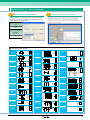
WindLGC Ver. 6.*: New Functions
d
ate
Upd
d
ate
Improvement of function blocks 1
Upd
Improvement of function blocks 2
When using simulation or online test on WindLGC, changes of
analog output values (AQ), current values (PV), and set-values
(SP) can be shown in a trend graph for easy monitoring of the
changes. Sampling period can be also chosen in one-second
increments, so that the chronological changes can be confirmed
accurately and more easily.
The addition of function blocks that can be set as parameters
makes it possible to achieve optimization of the entire program
and flexible programming through the coordination of function
blocks necessary for programming.
No. of function blocks
which can set as parameters
22
No. of function blocks
which can be used as
parameter
preset values
8
·SP (Set Point) obtained by referring to the analog value of the linked function
block can also be shown in the trend graph (WindLGC V.6.1.16 and up).
Special Function Blocks
On-delay
Off-delay
On-/Offdelay
Retentive
on-delay
Latching
Relay
Current
impulse relay
Interval timedelay relay/
Pulse output
Q
T
Trg
Q
TH
Trg
R
Q
T
Twelvemonth time
switch
Up/down
counter
(100617)
Trg
R
Par
Q
Trg
Par
Q
Trg
R
Par
T
S
R
RS
Q
S
R
Par RS
Trg
Q
Trg
Par
T
Trg
R
TL
No1
Sa Su
ON 12:00
OFF 20:00
Su
ON 8:00
OFF 22:00
No2
Q
TH
Sa
12
TL
MM.DDt
Q
8
0
22
20
No1
No2
No3
Fed. Mar. Apr.
25
R
Cnt
Dir 3
Par 21
Par
Operating
hours
counter
25
No
R
Cnt
Dir
Par
OFF=On+
Asynchronous pulse
generator
Q
En
Aen+
Aen
AenX
A
Q
R
En
Ral
Q
MN=MI
R
En
Ral
Par
MN=0
En
Inv
Q
TH
En
Inv
Par
TL
Trg
Q
Fre
G-T
Q
Q
Q
Q
S1
S2
S3
S4
S5
S6
S7
S8
0
0
0
0
1
1
0
0
1
0
0
0
0
1
1
0
0
1
0
0
0
0
1
1
fa=5Hz
fa=3Hz
1s
1s
Fre
Par
Ax
Par
Q
Ay
PI control
1
0
1
0
0
0
0
1
1
1
0
1
0
0
0
0
Analog
ramp control
1000
0
Ax
Ay
Par
0
1000
200
Ax-Ay
Q
0
En
Sel
St
MaxL
Level 2
Level 1
Ra
StSp+B
Q
Pulse width
modulator
(PWM)
0
1
1
0
1
0
0
0
1
1
0
1
0
0
0
1
Q
2
3
AQ
te
Ra
te
Ra
te
Ra
te
100 ms
100 ms 100 ms
En
S1
S2
V1
V2
V3
0
V4
AQ
En
Max =1000
Ax = 500
Min = 0
Q
AQ
Q
S4=Q (Example)
AQ
B
Q
En
Par
In
Trg
Dir
Par
500 ms
Q
Analog
multiplexer
1000
1
Max
SP PV
Min
Mq
Q
Q
Shift Down
A/M
R
/+ Dir
Q
when Ax – Ay > 200,
On and OFF threashold values = 200
MM
DD Q
Shift register
En
P
Par
Ax
Par
Analog
amplifier
In
Trg
Q
Dir
TL
On
Off
Ax 0
Ax
Analog
comparator
Q
Q
h
Switch
Shift Up
En
Par
Q
T Starts
1000
Analog
trigger
Message
texts
Softkey
En
Ax
Par
En
TH
Frequency
trigger
Q
AX
Q
Q
Q
Ax
Par
AX
Q
OFF=On+
OT
Su
20 12 20
12 20 8
No 02.25
No 04.15
TH
Analog value
monitor
Random
generator
Trg
S
R
Q
Analog
differential
trigger
Q
Par
Trg
Q
Q
TL
S
R
Q
Edge-trigTrg
gered interval
Q
time-delay
relay
Seven-day
time switch
T
Trg
R
Q
o
n
Trg
Par
Trg
← 2sec. →
← 2sec. →
← 2sec. →
← 2sec. →
← 2sec. →
← 2sec. →
← 2sec. →
A/M
R
PV
Par
AQ
En
Sel
St
Par
AQ
En
S1
S2
Par
AQ
En
Ax
Par
Q
Trg
Stairwell
light switch
Dual-function
switch
Trg
Par
Q
T
1s
T Starts
Trg
Q
TL
Analog math
Q
Analog math
error detection
En
Par
AQ
15s
TL
TIL
T1
T
Q
Trg
R
Par
En
R
Par
Q
9
FL1E
New IDEC SmartRelay with enhanced performance and visibility!
Advanced features enable pulse width modulation (PWM) and analog maths functions.
• A maximum of 200 function blocks can be programmed,
including 27 internal relays, 50 message displays, and an
unlimited number of timers and counters to achieve powerful control operations (program capacity 3,800 bytes).
• 10A relay outputs eliminate the need for external relays.
• Expandable up to 24 digital inputs, 16 digital outputs, 8
analog inputs, and 2 analog outputs.
• AS-Interface and LONWORKS® communication modules
enable decentralized control.
• An optional text display available. Easy operation from the
control panel.
• All base and expansion modules are UL/c-UL listed, FM
approved, IEC61131/VDE0631 compliant, Australian
EMC compliant, and marine certified (ABS, BV, DNV, GL,
Lloyd’s Register, and Class NK.)∗
∗ Surge protection device (DEHN + SÖHNE GmbH + Co, BVT AD 24 Part
No. 918 402) is required for marine certification when using 12/24V and
24V DC SmartRelay modules.
Types
•Base Modules
Rated Power Voltage
24V DC
Package Quantity: 1
Input Signal
Output Signal
Transistor
12/24V DC
DC
I1, I2, I7 and I8 are used for
digital/analog inputs
24V AC/DC
AC/DC (Note 2)
Relay
100 to 240V AC/DC
AC/DC
Relay
Relay
Display
Yes
Yes
—
Yes
—
Yes
—
Clock
Yes (Note
I/O Points
8/4 points
1)
Yes
8/4 points
Yes
8/4 points
Yes
8/4 points
Weight (approx.)
150g
190g
180g
190g
180g
195g
185g
Type No.
FL1E-H12SND
FL1E-H12RCE
FL1E-B12RCE
FL1E-H12RCA
FL1E-B12RCA
FL1E-H12RCC
FL1E-B12RCC
Note 1: Note: FL1E-H12SND of Ver. 5 has clock function. Ver. 2, 3, and 4 do not have clock function.
Note 2: With NPN/PNP sensor input. For details, see “Input Internal Circuits” on page 14.
•Expansion I/O Modules Type
Package Quantity: 1
Rated Power Voltage
24V DC
12/24VDC
24V AC/DC
100 to 240V AC/DC
12/24V DC
24V DC
Input/Output
Analog Input
Analog Output
Input Signal
DC
DC
AC/DC *
AC/DC
Analog
—
Output Signal
Transistor
Relay
Relay
Relay
—
Analog
I/O Points
4/4 points
4/4 points
4/4 points
4/4 points
2/0 points
0/2 points
Weight (approx.)
90g
125g
125g
130g
80g
90g
Type No.
FL1B-M08B1S2
FL1B-M08B2R2
FL1B-M08D2R2
FL1B-M08C2R2
FL1B-J2B2
FL1D-K2BM2
* With NPN/PNP sensor input. For details, see “Input Internal Circuits” on page 14.
•• I/O points within the maximum number of expandable I/O points can be used.
•• Use of a base module and expansion I/O modules of the same power voltage rating is recommended, with power supplied to all modules using one power supply. When power is supplied to the modules from different power supplies, the fast transient noise is 1 kV (IEC61000-4-4).
•Communication Modules
Package Quantity: 1
Name
Rated Power Voltage
AS-Interface Communication Module
30V DC (AS-Interface rated voltage)
LONWORKS® Communication Module
24V AC/DC
I/O Points
Input:
4 points
Output:
4 points
Input:
16 points
Analog input: 8 points
Output:
2 points
Weight (approx.)
Type No.
75g
FL1B-CAS2
85g
FL1B-CL1C12
• An external interface file (XIF extension) unique to each LONWORKS® communication module is needed to communicate through the LONWORKS® network. The XIF file can be downloaded from: http://www.idec.com/download/
•Text Display for FL1E
Rated Power Voltage
24V AC/DC
12V DC
Package Quantity: 1
Weight (approx.)
Type No. (Ordering Type No.)
220g
FL1E-RD1
Remarks
Supplied with text display cable, mounting clip and waterproof gasket
•Option
Name
Application Software Program WindLGC
Communication Cable
USB Communication Cable
Memory Cartridge
Battery Cartridge
Memory/Battery Cartridge
Mounting Clip for Base Module
Mounting Clip and Waterproof Gasket for Text Display
Text Display Cable
Lens Removal Tool
IDEC SmartRelay User’s Manual (English)
LONWORKS® Communication Module User’s Manual (English)
10
Type No.
FL9Y-LP1CDW
FL1A-PC1
FL1E-PC2
FL1E-PM4
FL1E-PB1
FL1E-PG1
FL1B-PSP1
FL1E-KW1
FL1E-RDC1
MT-101
FL9Y-B1090
FL9Y-B695
Ordering Type No.
FL9Y-LP1CDW
FL1A-PC1
FL1E-PC2
FL1E-PM4
FL1E-PB1
FL1E-PG1
FL1B-PSP1PN05
FL1E-KW1
FL1E-RDC1
MT-101
FL9Y-B1090
FL9Y-B695
Package Quantity
1
1
1
1
1
1
5
1
1
1
1
1
Remarks
CD-ROM (incl. online help manual)
With read/write protect function
Backup duration 2 years (typ.)
Supplied with a module
Supplied with text display
Length: 2.5m
For removing memory and cartridges
Downloadable from:
http://www.idec.com/download/
(100617)
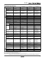
FL1E
Base Module Specifications
Base Module Type No.
FL1E-H12SND
Rated Power Voltage
24V DC
Allowable Voltage Range
20.4 to 28.8V DC
10.8 to 28.8V DC
—
—
Power Supply
Rated Frequency
Current Draw
40 to 75 mA (24V DC)
Allowable Momentary Power
Interruption
Clock
Power Consumption
76 to 182 mA (12V DC)
40 to 100 mA (24V DC)
2 ms Typ. (12V DC)
5 ms Typ. (24V DC)
5 ms Typ. (24V AC/DC)
0.7 to 2.1W (12V DC)
1.0 to 2.4W (24V DC)
1.8 to 4.4 VA (24V AC)
1.0 to 2.4W (24V DC)
Yes
Yes
80 hours (Note 1) (Note 5)
80 hours (Note 1)
80 hours (Note 1)
Clock Accuracy
±5 sec/day maximum (Note 5)
±5 sec/day maximum
±5 sec/day maximum
±5 sec/day maximum
Input Signal
DC
DC
AC/DC
AC/DC
Input Points
8 (I1 to I8)
8 (I1 to I8)
8 (I1 to I8)
Analog Input Points
4 (I1, I2, I7, I8)
4 (I1, I2, I7, I8)
—
—
High-speed Input (Note 2)
4 (I3, I4, I5, I6), 5 kHz maximum
0 to 10V DC
(max. rated input: 28.8V DC)
±1.5 (of full scale)
—
—
—
—
Analog Input Error
4 (I3, I4, I5, I6), 5 kHz maximum
0 to 10V DC
(max. rated input: 28.8V DC)
±1.5 (of full scale)
—
—
Analog Input Resolution
10 bits (0 to 1000)
10 bits (0 to 1000)
—
Input Impedance
Input
1.0 to 1.8W (24V DC)
60 to 175 mA (12V DC)
40 to 100 mA (24V DC)
0 to 28.8V DC
0 to 28.8V DC
Digital Input
3.5 kΩ
3.5 kΩ
Analog Input
72 kΩ
Isolation
—
FL1E-H12RCC
FL1E-B12RCC
100 to 240V AC/DC
85 to 265V AC
100 to 253V DC
47 to 63 Hz
25 to 40 mA (100V AC)
20 to 30 mA (240V AC)
10 to 25 mA (100V DC)
6 to 15 mA (240V DC)
10 ms Typ. (100V AC/DC)
20 ms Typ. (240V AC/DC)
2.8 to 4.6 VA (100V AC)
4.8 to 7.2 VA (240V AC)
1.1 to 2.9 W (100V DC)
1.4 to 3.6 W (240V DC)
—
Reverse Polarity Protection
Allowable Voltage Range
72 kΩ
—
—
0 to 265V AC
0 to 253V DC
840 kΩ
—
—
—
—
< 5V DC
< 5V DC
< 5V AC/DC
ON Voltage
≥ 12V DC
≥ 8.5 V DC
≥ 12V AC/DC
< 0.85 mA (I3 to I6)
< 0.05 mA (I1, I2, I7, I8)
≥ 2 mA (I3 to I6)
≥ 0.15 mA (I7, I8)
< 0.85 mA (I3 to I6)
< 0.05 mA (I1, I2, I7, I8)
≥ 1.5 mA (I3 to I6)
≥ 0.1 mA (I1, I2, I7, I8)
Turn ON Time
1.5 ms (Typ.)
≤ 1.0 ms (I3 to I6)
1.5 ms (Typ.)
≤ 1.0 ms (I3 to I6)
1.5 ms (Typ.)
Turn OFF Time
1.5 ms (Typ.)
≤ 1.0 ms (I3 to I6)
1.5 ms (Typ.)
≤ 1.0 ms (I3 to I6)
15 ms (Typ.)
OFF Current
80 hours (Note 1)
8 (I1 to I8)
0 to 26.4V AC
0 to 28.8V DC
4.8 kΩ
OFF Voltage
Operating
Range
—
< 40V AC
< 30V DC
≥ 79V AC
≥ 79V DC
< 1.0 mA
< 0.03 mA
Wire Length
100m (Note 3)
100m (Note 3)
100m
≥ 0.08 mA (AC)
< 0.12 mA (DC)
100V AC: 50 ms (Typ.)
240V AC: 30 ms (Typ.)
100V DC: 25 ms (Typ.)
240V DC: 15 ms (Typ.)
100V AC: 65 ms (Typ.)
240V AC: 105 ms (Typ.)
100V DC: 95 ms (Typ.)
240V DC: 125 ms (Typ.)
100m
Output Signal
Output Points/
Contact Configuration
Isolation
Dielectric Strength
(between power/input terminals
and output terminals)
Output Voltage
Transistor source output
Relay output
Relay output
Relay output
4 points (separate)
4NO contacts
4NO contacts
4NO contacts
—
Isolated
Isolated
Isolated
—
2500V AC, 1 minute
500V DC, 1 minute
2500V AC, 1 minute
500V DC, 1 minute
2500V AC, 1 minute
500V DC, 1 minute
Maximum Load Current
0.3A maximum
Surge Current
—
Built-in current limiting resistor:
Approx. 1A
—
—
Resistive load
10A at 12/24V AC/DC
10A at 100/120V AC
10A at 230/240V AC
Inductive load
2A at 12/24V AC/DC
3A at 100/120V AC
3A at 230/240V AC
30A maximum
External fuse required:
16A maximum
10 mA, 2V DC
100 mΩ maximum
(at 1A, 24V DC)
10 million operations
(no load, 10 Hz)
100,000 operations
(rated resistive load)
1800 operations/hour
10 Hz
—
Resistive load
10A at 12/24V AC/DC
10A at 100/120V AC
10A at 230/240V AC
Inductive load
2A at 12/24V AC/DC
3A at 100/120V AC
3A at 230/240V AC
30A maximum
External fuse required:
16A maximum
10 mA, 12V DC
100 mΩ maximum
(at 1A, 24V DC)
10 million operations
(no load, 10 Hz)
100,000 operations
(rated resistive load)
1800 operations/hour
10 Hz
ON Current
Output
—
FL1E-H12RCA
FL1E-B12RCA
24V AC/DC
20.4 to 26.4V AC
20.4 to 28.8V DC
47 to 63 Hz
Backup Duration
Analog Input Range
Short-circuit Protection
Minimum Switching Load
Switching
Rate
FL1E-H12RCE
FL1E-B12RCE
12/24V DC
External power voltage
Initial Contact Resistance
—
Mechanical Life
—
Electrical Life
—
Mechanical Load (Note 4)
—
≥ 2.5 mA
Electrical Load
10 Hz
Resistive Load/Lamp Load
10 Hz
2 Hz
—
2 Hz
—
2 Hz
—
Inductive Load
0.5 Hz
0.5 Hz
0.5 Hz
0.5 Hz
Note 1: 2 year backup duration (typ.) when battery cartridge or memory/battery cartridge is used.
Note 2: When selecting frequency trigger function and up/down counter function.
Note 3: 10m when connected to analog input (twisted pair cable)
Note 4: For fluorescent lamps, if the inrush current exceeds the allowable value, use an appropriate relay.
Note 5: FL1E-H12SND of Ver. 4 and before does not have clock function.
Initialization Time: After power-up, the FL1E takes a maximum of 10 seconds (when using a memory cartridge or memory/battery cartridge) or 9 seconds (without using
any cartridges or when using a battery cartridge) for initialization. When initialization is complete, the FL1E is automatically set to RUN mode.
(100617)
11
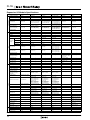
FL1E
Expansion I/O Module Specifications
Expansion I/O Module Type No.
FL1B-M08B1S2
Power Supply
FL1B-J2B2
24V AC/DC
100 to 240V AC/DC
12/24V DC
Allowable Voltage Range
20.4 to 28.8V DC
10.8 to 28.8V DC
20.4 to 26.4V AC
20.4 to 28.8V DC
85 to 265V AC
100 to 253V DC
10.8 to 28.8V DC
50/60Hz (47 to 63Hz)
50/60Hz (47 to 63Hz)
Current Draw
—
30 to 45 mA
Allowable Momentary
Power Interruption
—
—
30 to 140 mA (12V DC)
20 to 75 mA (24V DC)
120 to 146 mA (24V AC)
20 to 75 mA (24V DC)
2 ms (typ.) (12V DC)
5 ms (typ.) (24V DC)
5 ms (typ.) (24V AC/DC)
34 to 45 mA (100V AC)
30 to 32 mA (240V AC)
5 to 15 mA (100V DC)
5 to 10 mA (240V DC)
10 ms (typ) (100V AC/DC)
20 ms (typ.) (240V AC/DC)
3.9 to 4.1VA (100V AC)
7.4 to 7.6VA (240V AC)
0.5 to 1.8W (100V DC)
1.2 to 2.4W (240V DC)
35 to 90 mA
5 ms (typ.) (12/24V DC)
5 ms (typ.)
0.3 to 0.6W (12V DC)
0.6 to 1.2W (24V DC)
0.9 to 2.2W
Yes
2.4 to 4.3VA (24V AC)
0.4 to 1.8W (24V DC)
Reverse Polarity
Protection
Yes
Yes
—
—
Yes
Input Signal
DC input
DC input
AC/DC input
AC/DC input
Analog input
Input Points
4
4
4
4
—
—
—
—
0 to 28.8V DC
0 to 26.4V AC
0 to 28.8V DC
0 to 265V AC
0 to 253V DC
< 40V AC
< 30V DC
≥ 79V AC
≥ 79V DC
< 5V DC
< 5V DC
< 5V AC/DC
≥ 12V DC
≥ 8.5V DC
≥ 12V AC/DC
—
—
0 to 28.8V DC
OFF Voltage
—
25 to 50 mA
0.3 to 1.7W (12V DC)
0.4 to 1.8W (24V DC)
ON Voltage
20.4 to 28.8V DC
—
0.8 to 1.1W
Operating
Range
FL1D-K2BM2
24V DC
Power Consumption
Isolation
Input
FL1B-M08C2R2
12/24V DC
Allowable Voltage Range
—
—
—
—
—
—
—
—
—
OFF Current
< 0.85 mA
< 0.85 mA
< 1.0 mA
< 0.03 mA
—
—
ON Current
≥ 2 mA
≥ 1.5 mA
≥ 2.5 mA
≥ 0.08 mA
—
—
Turn ON Time
1.5 ms (Typ.)
1.5 ms (typ.)
1.5 ms (typ.)
—
—
Turn OFF Time
1.5 ms (Typ.)
1.5 ms (typ.)
15 ms (typ.)
—
—
Analog Input Points
—
Analog Input Range
—
—
100V AC: 50 ms (typ.)
240V AC: 30 ms (typ.)
100V DC: 25 ms (typ.)
240V DC: 15 ms (typ.)
100V AC: 65 ms (typ.)
240V AC: 105 ms (typ.)
100V DC: 95 ms (typ.)
240V DC: 125 ms (typ.)
—
—
—
—
2
—
—
0 to 10V (max. rated
input: 28.8V)
0 to 20 mA (max. rated
input: 40 mA)
—
Digital Resolution
—
—
—
—
10 bits (0 to 1000)
—
Input Error
—
—
—
—
±1.5% (of full scale)
—
Input Impedance
—
—
—
—
76 kΩ (0 to 10V)
250Ω (0 to 20mA)
—
Sampling Cycle
—
—
—
—
50ms
—
10m (twisted-pair
shielded cable)
Wire Length
100m
100m
100m
100m
Output Signal
Transistor source output
Relay output
Relay output
Relay output
Output Points/
Contact Configuration
4 points (separate)
—
—
Analog output
4NO contacts
4NO contacts
4NO contacts
—
—
Isolation
—
Isolated
Isolated
Isolated
—
—
Dielectric Strength
(between power/input
terminals and output
terminals)
—
2500V AC, 1 minute
500V DC, 1 minute
2500V AC, 1 minute
500V DC, 1 minute
2500V AC, 1 minute
500V DC, 1 minute
—
—
—
—
—
—
Output Voltage
Output
FL1B-M08D2R2
24V DC
Rated Frequency
Switching
Rate
FL1B-M08B2R2
Rated Power Voltage
External power voltage
(20.4 to 28.8V DC)
Maximum Load Current
0.3A maximum
Short-circuit Protection
Built-in current limiting
resistor: Approx. 1A
Minimum Switching Load
—
Initial Contact Resistance
—
Mechanical Life
—
Electrical Life
—
Analog Output Points
—
Analog Output Range
—
—
—
—
Resistive load
5A at 12/24V AC/DC
5A at 100/120V AC
5A at 230/240V AC
Inductive load
2A at 12/24V AC/DC
3A at 100/120V AC
3A at 230/240V AC
External fuse required:
16A maximum
Resistive load
5A at 12/24V AC/DC
5A at 100/120V AC
5A at 230/240V AC
Inductive load
2A at 12/24V AC/DC
3A at 100/120V AC
3A at 230/240V AC
External fuse required:
16A maximum
Resistive load
5A at 12/24V AC/DC
5A at 100/120V AC
5A at 230/240V AC
Inductive load
2A at 12/24V AC/DC
3A at 100/120V AC
3A at 230/240V AC
External fuse required:
16A maximum
10 mA, 12V DC
10 mA, 12V DC
10 mA, 12V DC
100 mΩ maximum
(at 1A, 24V DC)
10 million operations
(no load, 10 Hz)
100,000 operations
(rated resistive load)
1800 operations/hour
—
100 mΩ maximum
(at 1A, 24V DC)
10 million operations
(no load, 10 Hz)
100,000 operations
(rated resistive load)
1800 operations/hour
—
100 mΩ maximum
(at 1A, 24V DC)
10 million operations
(no load, 10 Hz)
100,000 operations
(rated resistive load)
1800 operations/hour
—
—
—
—
—
Yes
—
—
—
—
—
—
—
—
—
—
Digital Resolution
—
—
—
—
—
Output Error (of full scale)
—
—
—
—
—
Output Impedance
—
—
—
—
—
2
Voltage: 0-10V DC
Current: 0-20, 4-20 mA
10 bits (0 to 1000)
Voltage output: ±2.5%
Current output: ±3%
Voltage: 5 kΩ minimum
Current: 250Ω maximum
Analog Value
Conversion Interval
—
—
—
—
—
Wire Length
—
—
—
—
—
—
—
—
Mechanical Load (Note)
Electrical Load
Resistive Load/
Lamp Load
Inductive Load
—
10 Hz
10 Hz
10 Hz
—
10 Hz
—
—
50 ms (typ.)
10m (twisted-pair
shielded cable)
—
10 Hz
2 Hz
2 Hz
2 Hz
—
—
0.5 Hz
0.5 Hz
0.5 Hz
0.5 Hz
—
—
Note: For fluorescent lamps, if the inrush current exceeds the allowable value, use an appropriate relay.
12
(100617)
FL1E
Relative Humidity
0 to 55°C
Standard
Cold: IEC60068-2-1
Hot: IEC60068-2-2
0 to 55°C
–40 to +70°C (no freezing)
10 to 95% (no condensation)
—
IEC60068-2-30
Atmospheric Pressure
795 to 1080 hPa
—
Operating Condition
No corrosive gas
—
Degree of Protection
IP20
—
Vibration Resistance
5 to 8.4 Hz, amplitude 3.5 mm
8.4 to 150 Hz, acceleration
9.8 m/s2
m/s2
IEC60068-2-6
IEC60068-2-27
Shock Resistance
147
Drop Test (packaged)
0.3m
IEC60068-2-32
Limit class B Group 1 (Note 1)
EN55011/A
EN55022/B
EN50081-1
Emissions
Electrostatic Discharge
Immunity
Radiation Field Immunity
Fast Transient Burst
Surge Immunity (Note 4)
(FL1E-H12RCC,
FL1E-B12RCC only)
8 kV air discharge
6 kV contact discharge (Note 2)
Field Strength:
1 V/m and 10 V/m
2 kV (power line)
1 kV (I/O signal line) (Note 3)
1 kV (power line) normal
2 kV (power line) common
IEC61000-4-2
IEC61000-4-3
IEC61000-4-4
IEC61000-4-5
mm2
Communication Cable
(one wire)
0.5 to 2.5
0.5 to 1.5 mm2 (two wires)
—
Terminal Style
Finger-safe type (Note 5)
—
Note 1: Class A for AS-Interface communication module
Note 2: 8 kV (air discharge), 4 kV (contact discharge) for AS-Interface communication
module
Note 3: 1 kV (criteria A), 2 kV (criteria B) for AS-Interface communication module
Note 4: For protection against surge noise on DC power supply types (FL1E-H12RCE/
B12RCE, FL1E-H12SND, FL1E-H12RCA/B12RCA), use surge absorbers, noise
cut transformers, or noise filters. Use of a surge protection device (DEHN +
SÖHNE GmbH + Co, BVT AD 24 Part No. 918 402) is recommended.
Note 5: Tightening torque 0.4 to 0.5 N·m
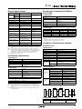
Text Display Specifications
•Specifications
Dimensions (W × H × D)
Weight (approx.)
Installation
Keyboard
Display
128.2 × 86 × 38.7 mm
220g
Panel cut-out using mounting clips
Membrane keypad with 10 keys
FSTN graphic display
(W × H: 128 × 64 dots)
LED backlight
•Power Supply
Power Voltage
Allowable Voltage Range
Allowable Voltage Frequency
Power Consumption
Data Transmission Rate
24V AC/DC
12V DC
20.4 to 26.4V AC
10.2 to 28.8V DC
47 to 63Hz
12V DC: 65 mA (Typ.)
24V DC: 40 mA (Typ.)
24V AC: 90 mA (Typ.)
19200 baud
•LCD Display / Backlight
LCD Display Durability (Note 1)
Backlight Durability (Note 2)
50,000 hours
20,000 hours
∗Connect the text display and the base module using the text display cable (2.5m). The text
display cable can be extended up to 10m using an extension cable (D-sub 9-pin).
•Specifications
Module Type
Slave Type
AS-Interface slave module
Standard
I/O code: 7
ID code: F
ID2 code: F
Profile
Input/Output
Virtual input: 4
Virtual output: 4
Rated AS-Interface Voltage
Current Draw
30V DC (26.5 to 31.6V DC)
70 mA max. (AS-Interface)
•I/O Allocation
Input
Output
AS-Interface
SmartRelay
SmartRelay
AS-Interface
Output Data Bit D0
Input In
Output Qm
Input Data Bit D0
Output Data Bit D1
Input In+1
Output Qm+1
Input Data Bit D1
Output Data Bit D2
Input In+2
Output Qm+2
Input Data Bit D2
Output Data Bit D3
Input In+3
Output Qm+3
Input Data Bit D3
• I/O point numbers “n” and “m” of the SmartRelay are automatically allocated by the
base module according to the mounted position of the AS-Interface communication
module.
• AS-Interface communication module is IP20 terminal type.
• AS-Interface cable is connected to the terminal block.
LONWORKS® Communication Module:
FL1B-CL1C12
•Specifications
Rated Power Voltage
24V AC/DC (20.4 to 26.4V AC / 20.4 to 28.8V DC)
Rated Frequency
50/60 Hz (47 to 63 Hz)
Current Draw
33 mA max.
Communication System
LON® system
Transceiver
FTT-10A
Topology
Bus topology / Free topology
Transmission Rate
78 kbps
Neuron Chip
TMPN3120FE5M (Toshiba)
CPU Clock Frequency
Transmission
Distance
20 MHz
Bus topology
1,400m (only FTT-10A transceiver, when using
Level 4 AWG22 cable)
Free topology
500m total, 400m between nodes
(when using Level 4 AWG22 cable)
•Network Variables
SNVT Type
Application
SNVT_obj_request: (Quantity 1)
Input Network
Variable
Output Network
Variable
Request object status
SNVT_switch: (Quantity 14)
Switch light, alarm, window contact,
free inputs/outputs
SNVT_occupancy: (Quantity 2)
Occupancy
SNVT_temp_p: (Quantity 1)
Room temperature (°C)
SNVT_lux: (Quantity 1)
Brightness - lightening level (lux)
SNVT_lev_percent: (Quantity 6)
Position (%)
SNVT_obj_status: (Quantity 1)
Output object status
SNVT_switch: (Quantity 8)
Switch light, alarm, window contact,
free inputs/outputs
SNVT_occupancy: (Quantity 2)
Occupancy
SNVT_tod_event: (Quantity 2)
Scheduler program
Just current state
•Block Diagram
20 MHz
20 MHz
TXD
TXD
LON
Internal Bus
Note1: Display durability is calculated under ordinary operating and storage conditions:
room temperature, normal humidity below 65% RH, and not subjected to direct
sunlight.
Note 2: Backlight durability is the number of hours taken for the light to become 50% of
the original brightness.
AS-Interface Communication Module:
FL1B-CAS2
Neuron
Chip
CPU
RXD
RXD
RXD NET-A
FTT-10A
X2
TXD NET-B
NET-A
Horizontal
Mounting
Vertical
Mounting
Storage/Transportation
Temperature
Operating
Temperature
Specifications
NET-B
Item
Interface Circuit
General Specifications
•Configuration Property
SCPT Type
Configuration
Property
(100617)
SCPTmaxSendTime: (Quantity 12)
Application
Send heartbeat
13
FL1E
Input Internal Circuits
Analog Current Input
•• FL1B-J2B2
DC Input
•• FL1E-H12SND, -H12RCE, -B12RCE
•• FL1B-M08B1S2, -M08B2R2
L+
I3 to I6
3.6 k
270 k
0V
DC
3-wire Sensor
Internal
Circuit
•• FL1E-H12RCA, -B12RCA
•• FL1B-M08D2R2
Internal
Circuit
NPN
Output
3.6 k
OUT
270 k
I3 to I6
100 nF
I1 to I8
L+ (12/24V DC)
OUT
Internal
Circuit
I1, I2, I7, I8
+5V
M
0V
P1 (0V)
Note 4: Bleeder resistance (R6) calculation
R6 must satisfy the following three conditions.
Condition 1: R6 (Ω) ≤
Maximum input OFF voltage (= 5V AC)
I1 to I8
AC
2-wire
Sensor
R6
Maximum sensor leakage current (A)
P1
24V AC
Sensor power voltage (V)
Minimum sensor load current (A)
P2
The voltage drop across the load (R6) must be less than 5V while the sensor is turned off.
{Sensor power voltage (V)}2
R6 resistance (Ω)
× 3 (3: recommended allowance)
100 to 240V AC/DC
Note 2: I1, I2, I7 and I8 accept both digital and analog inputs. The diagram above is for
using I1, I2, I7, and I8 as digital inputs.
When using an NPN output sensor, connect an external resistor (I1, I2, I7, I8):
FL1E-H12SND
For power voltage 24V DC: R3 ≤ 50 kΩ, 1/8W
FL1E-H12RCE/-B12RCE
For power voltage 24V DC: R3 ≤ 100 kΩ, 1/8W
For power voltage 12V DC: R3 ≤ 19 kΩ, 1/8W
Analog Voltage Input
•• FL1E-H12RCC, -B12RCC
•• FL1B-M08C2R2
L1
390 k
R7 270 k
I1 to I8
I1 to I8
AC
2-wire
Sensor
R9
Internal
Circuit
N
100 to 240V AC
R8
100 nF
L
FL1E-H12RCC, -B12RCC: R7=180 kΩ, R8=47 kΩ
FL1E-M08C2R2:
R7=390 kΩ, R8=62 kΩ
•• FL1E-H12SND, -H12RCE, -B12RCE
•• FL1B-J2B2
+
R4
0 to 10V
I1, I2, I7, I8
(U1, U2)
10 nF
–
M (M1, M2)
Note 5: Bleeder resistance (R9) calculation
Internal
Circuit
R9 must satisfy the following three conditions.
R5
Condition 1: R9 (Ω) ≤
Output Internal Circuits
Condition 2: R9 (Ω) ≤
Sensor power voltage (V)
Minimum sensor load current (A)
The voltage drop across the load (R9) must be less than 40V while the sensor is turned off.
Condition 3: PR9 (W) ≥
{Sensor power voltage (V)}2
DC Output (Transistor Source Output)
•FL1E-H12RCE, -B12RCE, -H12RCA,
-B12RCA, -H12RCC, -B12RCC 240V AC/24V DC
L1
L+
•FL1B-M08B2R2, -M08D2R2,
-M08C2R2
Fuse
240V max.
10A max.
Maximum sensor leakage current (A)
R9 resistance (Ω)
× 3 (3: recommended allowance)
Analog Voltage Output
Relay Output
Q1 to Q4
+24V Internal Circuit 2
Maximum input OFF voltage (= 40V AC)
+5V
FL1E-H12SND, -H12RCE, -B12RCE:
R4 = 54 kΩ, R5 = 18 kΩ
FL1B-J2B2 :
R4 = R5 = 38 kΩ
Note 3: I1, I2, I7, and I8 accept both digital and analog inputs. When connecting an
analog input, use a twisted pair cable, and keep the cable as short as possible.
1
I1 to I8
DC
3-wire Sensor
Condition 3: PR6 (W) ≥
10 nF 18 k
DC
3-wire Sensor
P1 (0V)
Internal
Circuit
510
4.3 k
OUT
NPN
Output
Condition 2: R6 (Ω) ≤
54 k
0V
P2 (0V)
+V P2 (24V DC)
M
R3
NPN
Output
0V
R2
C1
+V
I1, I2,
I7, I8
DC
3-wire Sensor
Internal
Circuit
Note 1: When using an NPN output sensor, connect an external resistor (I3 to I6):
FL1E-H12SND:
For power voltage 24V DC: R1 ≤ 4 kΩ, 1/4W
FL1E-H12RCE, -B12RCE:
For power voltage 24V DC: R1 ≤ 8.1 kΩ, 1/4W
For power voltage 12V DC: R1 ≤ 1.5 kΩ, 1/4W
FL1E-H12SND, -H12RCE, -B12RCE:
R2 = 2.21 kΩ, C1 = 47 nF
FL1B-M08B1S2, -M08B2R2 (I1 to I4):
R2 = 2.2 kΩ, C1 = 100 nF
L+
510
100 nF
DC
3-wire Sensor
14
4.3 k
OUT
I1 to I8
0V
Internal
Circuit
PNP
Output
I1 to I8
L+ (12/24V DC)
R1
I3 to I6
+V P1 (24V DC)
P1 (24V)
R2
C1
M
+V
L+
M1, M2
24V AC/DC Input
OUT
I3 to I6
10 nF
125 kΩ
–
PNP
Output
Internal
Circuit
I1, I2
0 to 20 mA
L+ (12/24V DC)
+V
30 to 125Ω
+
L Load
•FL1E-H12SND
•FL1B-M08B1S2
•FL1D-K2BM2
(0-10V DC)
Internal
Circuit
+24V Internal Circuit
+
-
+24V Internal Circuit
10
(V1+, V2+)
100 nF
4.7 k
(M1, M2)
Q1 to Q4
Internal
Circuit
10 nF
10 kΩ
Fuse
24V DC
0.3A max. L Load
10 nF
M
N, M
Note 6: When connecting to a DC input type PLC, use a
negative common sink input type.
Analog Current Output
•FL1D-K2BM2
(0-20, 4-20 mA DC)
Internal
Circuit
+14V Internal Circuit
22Ω
(I1, I2)
10 nF
(M1, M2)
(100617)
FL1E
Dimensions
I2
I3
I4
I5
I6
I7
•Text Display
I8
Q1
Q2
Q3
86
I1
90
M
35
L+
4
•Base Module
F1
Q4
55
60
72
4
2
Q1
Q3
1
2
Q2
1
Q4
90
78.5 + 0.5mm
1
ESC OK
11 12 13 14
RUN/STOP
1
F4
119.5 + 0.5mm
4
M
35
L+
F3
128.2
38.7
(Panel Cutout)
•Expansion I/O Module, Communication Module
F2
2
2
55
58
36
•Panel Mounting
Mounting clip
•Mounting Hole Layout (Using Mounting Slides)
35.5+0.2
–0.0
53.5 +0.2
–0.0
98±0.3
Mounting screws
(tightening torque: 0.15 to 0.2 N·m)
Expansion
Expansion
Module
Module
Communication Communication
Module
Module
Base Module
Expansion
Module
Communication
Module
Mounting clip
2-ø4 Mounting Holes
Waterproof Gasket
n ×35.5 +0.2
–0.0
Panel (thickness: 1.5 to 4 mm)
All dimensions in mm.
Instructions
Module Expansion
Base module of rated operating voltage 12/24V DC, 24V DC, and 24V AC/DC
Use the base module, expansion I/O modules, and
communication modules according to the combinations
shown on the right.
Base Module
➀ 1st Expansion Module
12/24V DC
12/24V DC
24V DC
(incl.analog input,
communication module)
24V AC/DC
24V DC ∗
24V AC/DC
➁ 2nd Expansion Module
12/24V DC
24V DC ∗
(incl.analog input,
communication module)
24V AC/DC
➇ 8th Expansion Module
DC
DC
12/24V DC
24V DC ∗
(Analog)
(incl.analog input,
communication module)
AC
24V AC/DC
24V DC
Base module of rated operating voltage 100V to 240V AC/DC
➀
➁
➂
➃
➄
➅
➆
➇ ➈
*Only one LONWORKS® communication module can be
installed at the far right end of the row.
Base Module
100 to 240V AC/DC
➀ 1st Expansion Module
➁ 2nd Expansion Module
➈ 9th Expansion
Module
➇ 8th Expansion Module
100 to 240V AC/DC
100 to 240V AC/DC
AC
100 to 240V AC/DC
Analog input,
communication
Analog input,
communication
Analog
Analog input,
communication
(incl.analog output,
communication
module)
module ∗
module ∗
module ∗
1. A maximum of 9 expansion I/O modules and communication
modules can be connected to a base module.
12/24V DC
12V AC/DC
DC
2. A maximum of 4 combination I/O modules, 4 analog input modules,
and 1 analog output module can be connected to a base module.
24V DC
24V DC
DC
3. When using modules of the same power voltage, supply power to the base
module and expansion I/O modules using one power supply. When power is supAC
24V AC/DC
24V AC/DC
plied to the modules from different power supplies, the fast transient burst is 1 kV
(IEC61000-4-4).
4. A 100 to 240V AC/DC module cannot be connected to the right side of a 12/24V DC, 24V DC, or 24V AC/DC module.
5. For analog input module and AS-Interface communication module, a module of any voltage can be connected to the left side. To the
right side, however, a 100 to 240V AC/DC module cannot be connected.
6. Before connecting and disconnecting modules, turn power off.
AS-Interface Communication Module
•A maximum of 4 AS-Interface communication modules can be connected to a base module.
•AS-Interface communication module can be connected to any base module and expansion I/O modules.
• A 100 to 240V AC/DC module cannot be connected to the right side of AS-Interface communication module.
LONWORKS® Communication Module
•LONWORKS® communication module can be connected to any base module and expansion I/O modules.
•Only one LONWORKS® communication module can be installed. Always install the module at the far right end.
(100617)
15
FL1E
Instructions
Wiring
Initialization after Power-up
Base Module and Expansion I/O Module
•Connect an IEC60127 approved fuse to the power supply for
protection against overload and short circuit.
•Do not connect input wire and communication cable in parallel or
near the power line, output line, or motor line. Also make sure that
any noise source is not present nearby.
•Use 0.5 to 2.5 mm2 wires (for one-wire) or 0.5 to 1.5 mm2 wires
(for two-wire) for power line, input line, and output line (tightening
torque: 0.4 to 0.5 N·m).
LONWORKS® Communication Module
•Use LONWORKS® compatible cables for network wiring of the
LONWORKS® communication module.
•Initialization starts when the FL1E base module is powered up.
When initialization is complete, the FL1E is automatically set to
RUN mode. When using the FL1E base module with display, an
hourglass appears on the display during the initialization. When
using the FL1E without display, the red LED flashes during the
initialization.
•Initialization time
When a memory cartridge or memory/battery cartridge is used:
10 seconds maximum
When a cartridge is not used, or battery cartridge is used:
9 seconds maximum
∗Initialization time varies according the program size.
AS-Interface Communication Module
Purpose
Specification
Type No.
Signal / Power
EPDM (rubber) yellow
F-LINK-ASYE
Signal / Power
TPE (heat-resistant PVC) yellow
F-LINK-ASYT
Auxiliary Power
EPDM (rubber) black
F-LINK-ASBE
Auxiliary Power
TPE (heat-resistant PVC) black
F-LINK-ASBT
*Available from IDEC
•When connecting AS-Interface cable to an AS-Interface communication module, make sure that the brown cable is connected to
terminal +, and the blue cable to terminal –. The two + terminals
and two – terminals are both connected internally.
Enlarged View
Brown
Blue
AS-Interface Cable
Safety Precautions
••All IDEC SmartRelay devices are manufactured under IDEC’s
rigorous quality control system, but users must add a backup or
failsafe provision to the control system using the device in applications where heavy damage or personal injury may be caused in
case the device should fail.
••Turn off the power to the device before installation, removal, wiring, maintenance, and inspection of the device. Failure to turn
power off may cause electric shocks or fire hazard.
••Special expertise is required to install, wire, program, and operate
the IDEC SmartRelay devices. People without such expertise must
not use the IDEC SmartRelay devices.
••Read the user’s manual or operating instruction sheet attached to
the product to make sure of correct operation.
Specifications and other descriptions in this catalog are subject to change without notice.
7-31, Nishi-Miyahara 1-Chome, Yodogawa-ku, Osaka 532-8550, Japan
Tel: +81-6-6398-2571, Fax: +81-6-6392-9731
E-mail: [email protected]
IDEC CORPORATION (USA)
Wendenstrasse 331, 20537 Hamburg, Germany
Tel: +49-40-25 30 54 - 0, Fax: +49-40-25 30 54 - 24
E-mail: [email protected]
IDEC CANADA LIMITED
Room 608-609, 6F, Gangtai Plaza, No. 700,
Yan'an East Road, Shanghai 200001, PRC
Tel: +86-21-5353-1000, Fax: +86-21-5353-1263
E-mail: [email protected]
3155 Pepper Mill Court, Unit 4, Mississauga,
Ontario, L5L 4X7, Canada
Tel: +1-905-890-8561, Toll Free: (888) 317-4332
Fax: +1-905-890-8562
E-mail: [email protected]
IDEC AUSTRALIA PTY. LTD.
2/3 Macro Court, Rowville, Victoria 3178, Australia
Tel: +61-3-9763-3244, Toll Free: 1800-68-4332
Fax: +61-3-9763-3255
E-mail: [email protected]
IDEC ELECTRONICS LIMITED
www.idec.com
16
Unit 2, Beechwood, Chineham Business Park,
Basingstoke, Hampshire RG24 8WA, UK
Tel: +44-1256-321000, Fax: +44-1256-327755
E-mail: [email protected]
IDEC IZUMI (H.K.) CO., LTD.
IDEC ELEKTROTECHNIK GmbH
1175 Elko Drive, Sunnyvale, CA 94089-2209, USA
Tel: +1-408-747-0550 / (800) 262-IDEC (4332)
Fax: +1-408-744-9055 / (800) 635-6246
E-mail: [email protected]
IDEC (SHANGHAI) CORPORATION
Units 11-15, Level 27, Tower 1,
Millennium City 1, 388 Kwun Tong Road,
Kwun Tong, Kowloon, Hong Kong
Tel: +852-2803-8989, Fax: +852-2565-0171
E-mail: [email protected]
IDEC TAIWAN CORPORATION
8F-1, No. 79, Hsin Tai Wu Road, Sec. 1,
Hsi-Chih, Taipei County, Taiwan
Tel: +886-2-2698-3929, Fax: +886-2-2698-3931
E-mail: [email protected]
IDEC (BEIJING) CORPORATION
Room 211B, Tower B, The Grand Pacific Building,
8A Guanghua Road, Chaoyang District,
Beijing 100026, PRC
Tel: +86-10-6581-6131, Fax: +86-10-6581-5119
IDEC IZUMI ASIA PTE. LTD.
IDEC (SHENZHEN) CORPORATION
Unit AB-3B2, Tian Xiang Building, Tian’an Cyber Park,
Fu Tian District, Shenzhen, Guang Dong 518040, PRC
Tel: +86-755-8356-2977, Fax: +86-755-8356-2944
No. 31, Tannery Lane #05-01,
HB Centre 2, Singapore 347788
Tel: +65-6746-1155, Fax: +65-6844-5995
E-mail: [email protected]
Cat. No. EP1253-1-1 JUNE 2010 PDF
(100617)