1
Number 2639
Production Testing of High Intensity,
Visible LEDs using Series 2600 System
SourceMeter® Instruments
Application Note
Series
Introduction
Visible light emitting diodes (LEDs) have gained a reputation for
high efficiency and long lifetimes, which has led to their use in
a growing list of applications, including automotive displays and
exterior lights, street lights, outdoor signs, and video monitors.
Extensive research and development efforts by LED manufacturers have led to the creation of LEDs with higher brightness,
new colors, and longer lifetimes, which has driven demand and
encouraged an even wider array of applications. Now, more than
ever, cost-effective testing methods are needed to ensure the reliability and quality of these devices.
LED testing involves different types of test sequences at various stages of production, such as during design research and
development, on-wafer measurements during production, and
final tests of packaged parts. While concrete testing “recipes”
often include a multitude of steps intended to verify product
lifetime or extract data on specific performance characteristics,
they are beyond the scope of this application note. This note is
intended to provide solid information on the needed “ingredients” for these recipes—basic tests that illustrate how to probe
for the diodes’ characteristics and example test setups. This
note also outlines how to achieve throughput advantages by
using new test technologies, including instruments enabled with
Keithley’s Test Script Processor (TSP™).
Test Description
Testing LEDs typically involves both electrical and optical measurements. This note focuses on electrical characterization,
including light measurement techniques where appropriate.
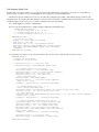
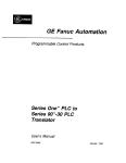
Figure 1 illustrates the electrical I-V curve of a typical diode. A
complete test could include a multitude of voltage values versus
current operating points, but a limited sample of points is generally sufficient to probe for the figures of merit.
I
Vf test
IL test
V
VR test
Figure 1. Typical LED DC I-V curve and test points (not to scale).
Some tests require sourcing a known current and measuring
a voltage, while others require sourcing a voltage and measuring
the resulting current. A SourceMeter instrument is ideal for these
types of tests because it can be configured to source voltages or
currents and can also measure each of these signal types.
Forward Voltage Test (VF) and Optical Tests
The V F test verifies the forward operating voltage of the visible
LED. When a forward current is applied to the diode, it begins to
conduct. During the initial low current source values, the voltage
drop across the diode increases rapidly, but the slope begins to
level off as drive currents increase. The diode normally operates
in this region of relatively constant voltage. It is also quite useful
to test the diode under these operating conditions. The forward
voltage test (V F) is performed by sourcing a known current and
measuring the resulting voltage drop across the diode. Typical
test currents are in the milliamps range, while the resulting voltage measurement is typically in the range of few volts.
Forward current biasing is also used for optical tests because
electrical current flow is closely related to the amount of light
emitted. Optical power measurements can be made by placing a
photodiode or integrating sphere close to the device under test
to capture the emitted photons. This light is then converted to a
current, which can be measured by an ammeter or a channel of a
SourceMeter instrument.
In many test applications, the voltage and light output of the
diode can be measured simultaneously using a fixed source current value. In addition, details such as spectral output can be
obtained by using the same drive current value and a spectrometer.
Reverse Breakdown Voltage (VR) and
Leakage Current (IL) Tests
Applying a negative bias current to the LED will allow probing
for the so-called Reverse Breakdown Voltage (V R). The test current should be set to a level where the measured voltage value
no longer increases significantly when the current is increased
slightly more. At levels higher than this voltage, large increases
in reverse bias current result in insignificant changes in reverse
voltage. The specification for this parameter is usually a minimum value. The test is performed by sourcing a low-level reverse
bias current for a specified time, then measuring the voltage
drop across the LED. The measurement result is typically in the
range of tens of volts.
Normally, moderate voltage levels (volts to tens of volts) are
used to measure a Leakage Current (IL). The Leakage Current
Test measures the low-level current that leaks across the LED
when a reverse voltage less than breakdown is applied. It is a
common practice for leakage measurements, and more generally for isolation measurements, to make sure only that a certain
threshold is not exceeded in production. There are two reasons
for this. First, low current measurements require longer settling
times, so they take longer to complete. Second, environmental
interference and electrical noise exert greater influence on lowlevel signals, so extra care in shielding is required. This extra
shielding complicates the test fixture and may interfere with
automated handlers.
Test System Description
Single LED Test System
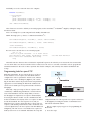
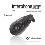
Figure 2 is a simplified block diagram of an LED test station. For
automation purposes, a PC and a component handler—a probe
station for on-wafer measurements—are included.
PD
LED
Component
Handler
Test Fixture
Bins
KPCI488
GPIB
2602
Channel A
2602
Channel B
Digital Lines
(DIO)
Figure 2. Block Diagram of a 2602 SourceMeter-Based Single LED Test System
The main purpose of the PC is to store measurement data in
a database for documentation. A secondary purpose is to reconfigure the test sequence for different parts.
Series 2600 instruments are unique in terms of their independence from the PC controller. Their internal Test Script
Processor supports writing a complete test plan that operates on
the instrument itself. In other words, a user can write a complete PASS/FAIL incoming inspection test sequence script and
run it from the front panel of the Model 2602 without instrument reprogramming.
A more production-oriented scenario would
look a bit different. In production, there may be
a component handler to transport the individual
LEDs to a test fixture, where it can be electrically
contacted. The fixture is shielded from ambient
light and houses a photodetector (PD) for light
measurements. In this setup, a single Model 2602
Dual-Channel System SourceMeter instrument can
be used for both connections. Source Measure Unit
A (SMUA) can be used to supply the test signal to
the LED and measure its electrical response while SMUB can be
used to monitor the photodiode during optical measurements.
The test sequence can be programmed to begin using a digital line from the component handler that can serve as a “start of
test” (SOT) signal. After the SourceMeter instrument detects the
SOT signal, the tests for characterization of the LED will begin.
After all electrical and optical tests are completed, a digital
line to flag “measurement complete” can be set for the component handler. In addition, the 2602’s built-in intelligence can perform all pass/fail operations and send a digital command through
the digital I/O port on the 2602 to the component handler to bin
the LED based on the pass/fail criteria. Then, usually two actions
can take place synchronously: data transfer to the PC for statistical process control (SPC) and the mechanical placement of a new
DUT in the testing fixture.
LED Test System for Multiple Devices/Arrays
In addition to single device testing, there are also multiple device
tests, such those that involve a burn-in process. In these tests,
multiple parts are measured over a specified time period. A continuous current flow is usually mandatory to drive the DUTs, but
multiple light detectors may be multiplexed to a current meter by
a switching system. The appropriate choices for switching system
and meter will be dictated by the dynamic range of electrical currents of interest.
Keithley offers a number of switch options applicable to testing multiple LEDs. Mainframes range from the two-slot Model
7001, capable of up to 80 channels of switching, to the ten-slot
Model 7002 mainframe, which can handle up to 400 channels.
Another option is the 7002-HD, which allows up to 320 channels in one of the world’s highest density switch mainframes. For
low-level current measurements, Keithley offers the Model 6485
Picoammeter and the Model 6487 Picoammeter/Voltage Source.
One of the Model 2602 SourceMeter channels can also be used
to measure currents.
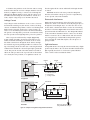
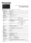
For smaller numbers of LEDs, multiple Series 2600 System
SourceMeter instruments can be used. Figure 3 illustrates a
three-LED device test system with one PD channel.
PD
LED 1
LED 2
LED 3
2602
Channel A
2602
Channel B
DIO
KPCI488
GPIB
2602
Channel A
2602
Channel B
TSP-Link
Figure 3. Block Diagram with scalable Model 2602 SourceMeter channels for an
LED Array Test System
Test Sequence Script Code
The following code snippets illustrate a test sequence script for the Model 2602 to perform three electrical tests on an LED. The
intention of the test steps is to serve as building blocks for creating more specialized applications.
The first part after the enumeration of tests is a one-time-only configuration providing a well-defined starting condition of the
instrument. Next, the output of the SMU channel is activated and the tests follow sequentially. The measurement data is stored in the
variable “Reading” and are sent to a PC via “print” commands at the end of the listing.
Note: double hyphens (--) indicate comment lines.
First, let’s put the instrument into a default setting by sending the following function:
-----
Example LED
1.) Forward
2.) Leakage
3.) Reverse
Test Sequence
Voltage Test VF at
10 mA
Current Test IL at -10 V
Breakdown Voltage Test VR at -5E-6 A
function ResetLED()
-- One Time Reset & Setup
Reading = {} --Create table for readings
smua.reset() --reset SMU
smua.measure.nplc = 0.01 --Set measurement aperture
smua.measure.autozero = smua.AUTOZERO_OFF --Disable autozero
smua.sense = smua.SENSE_REMOTE --Enable 4-wire measurement
--GlobalVar = 1
end--function ResetLED()
To perform the test sequence, we need another function that sets up each test and performs the proper actions:
function LEDTest()
--configure LED Test Sequence.
--Performs VF, IL, and VR tests
smua.source.levelv = 0 --Set source value
smua.source.output = smua.OUTPUT_ON --Enable source
--1.) Forward Voltage Test VF at 10 mA
smua.measure.rangev = 6 --Set measurement range
smua.source.limiti = 0.001 --Set source current compliance
smua.source.rangei = 0.1 --Set source range
smua.source.leveli = 0.01 --Set source level
--Select output function
smua.source.func = smua.OUTPUT_DCAMPS
smua.source.limitv = 6 --Set source voltage compliance
--delay (0.001) --Delay
Reading[1] = smua.measure.v() --Perform Vf measurement
--2.) Leakage Current Test IL at -10 V
--Select current measurement range
smua.measure.rangei = 1E-5smua.source.rangev = 40 --Select voltage source range
smua.source.levelv = -10 --Select voltage source value
--Set source function
smua.source.func = smua.OUTPUT_DCVOLTSsmua.source.limiti = 0.1 --Set source current compliance
--delay (0.005) --Delay
Reading[2] = smua.measure.i() --Perform IL measurement
--3.) Reverse Breakdown Voltage Test VR at -5E-6 A
smua.measure.rangev = 40 --Set voltage measurement range
smua.source.rangei = 1E-5 --Set current source range
smua.source.leveli = -5E-6 --Set current source level
smua.source.limitv = 40 --Set source voltage copliance
smua.source.func = smua.OUTPUT_DCAMPS --Set source function
delay (0.005) --Delay
Reading[3] = smua.measure.v() --Perform VR measurement
smua.source.leveli = 0 --Set source level
smua.source.output = smua.OUTPUT_OFF --Disable output
end--function LEDTest()
And finally, we need to return the data to the computer:
function ReturnData()
-- Data Printing
print (“”)
print (“Measurement reading at 10 mA:”.. Reading[1]..” V”)
print (“Measurement reading at -10 V:”.. Reading[2]..” A”)
print (“Measurement reading at -5 uA:”.. Reading[3]..” V”)
end --function ReturnData()
These functions can now be called by an external program, such as Visual Basic® or LabVIEW™ simply by sending the string of
the function name.
Here is an example for a system using VB6 and a Keithley 488 GPIB card:
NOTE: The single quote (‘) denotes a comment in Visual Basic® 6.
Call Send(KeithleyMeter, “ResetLED()”, status) ‘Calls ResetLED()
Call Send(KeithleyMeter, “LEDTest()”, status) ‘Calls LEDTest()
‘Calls ReturnData()
Call Send(KeithleyMeter, “ReturnData()”, status)
We now need to enter the data to our external program:
For I = 1,4
--There are 4 print statements.. so we need 4 enters
Call enter(Data, 1000, Length, KeithleyMeter, status)
Data = Data & Data ‘Concatenate data string
Loop
‘ Get info back from meter
This will return the characters that are held in the output buffer queue in the order they were written. The data return in this
case was ASCII. This is not the fastest method of data return, but it is the easiest to start with. Consult the software program and
instrument manuals for directions on more expedient data transfer techniques, such as binary data transfer and buffered data
storage.
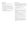
Programming tests for speed: TSP
With many instruments, the PC controls all aspects of the test.
In each element of a test sequence, the instruments must be
configured for each test, perform the desired action, and then
return the data to the controlling PC (Figure 4). The controlling PC then must evaluate the pass/fail criteria and perform the
appropriate action for binning the DUT. Each command sent
and executed consumes precious production time and lowers
throughput.
Obviously, a large percentage of this test sequence time is
consumed by communicating information to and from the PC.
Series 2600 instruments offer the unique ability to increase
the throughput of complicated test sequences dramatically by
decreasing the amount of traffic over the communications bus.
In these instruments, the majority of the test sequence is embedded in the instrument. The Test Script Processor (TSP) is a
full-featured test sequence engine that allows control of the test
sequence, with internal pass/fail criteria, math, calculations, and
control of digital I/O (see the Test Sequence with 2602 illustrated
in Figure 5). The TSP can store a user-defined test sequence in
memory and execute it on command. This limits the set-up and
Figure 4. PC control of standard instruments.
configuration time for each step in the test sequence and increases throughput by lessening the amount of communications to
and from the instrument and PC.
Here is a simple step-by-step process for programming the
Model 2602:
1) Create the script.
Therefore, it is important to shorten the test time as much as
possible without sacrificing measurement accuracy or stability.
Figure 5. Use of the embedded Test Script Processor (TSP) in the Model 2602
to store the test sequence. Note decreased communications traffic.
2) Download the script to the instrument.
3) Call the script to run.
The 2602 script can be written in the Test Script Builder software provided with the instrument or downloaded to the instrument using another program, such as Visual Basic or LabVIEW.
See Section 2 of the 2602 User’s Manual for more information on
programming the 2602.
Typical Sources of Error
Junction Self-Heating
With increasing test times, the semiconductor junction of the
LED will tend to heat. The two tests susceptible to junction heating are the forward voltage and leakage current tests. As the
junction heats, the voltage will drop, or, more importantly, the
leakage current will increase during the constant voltage test.
The Series 260x System SourceMeter family can configure
the device soak time before the measurement, as well as the
amount of time the input signal is acquired. The soak time
allows any circuit capacitance to settle before the measurement
begins. The measurement integration time is determined by the
number of power line cycles (NPLC). If the input power were at
60Hz, a 1NPLC measurement would require 1/60th of a second
or 16.667ms. The integration time defines how long the analogto-digital converter (ADC) acquires the input signal, and it represents a trade-off between speed and accuracy.
Typical soak times for the V F test are from less than one millisecond to five milliseconds, and from five to 20 milliseconds
for the IL test. By using these short test times, errors due to the
junction heating are reduced. Also, the junction heating characteristics can be determined by performing a series of tests and
only varying the test time.
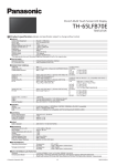
Lead Resistance
A common source of voltage measurement error is the series
resistance from the test leads running from the instrument to the
LED. This series resistance is added into the measurement when
making a two-wire connection (see Figures 6 and 8). The effects
of lead resistance are particularly detrimental when long connecting cables and high currents are used, because the voltage
drop across the lead resistance becomes significant compared to
the measured voltage.
Figure 8 depicts the situation with lead resistances drawn as
‘lumped’ components. The gray ‘rounded rectangle’ sketches current flow, which is nearly unaffected by high impedance voltage
meters.
Model 260X
Voltage drop
V = I·R
R = Lead resistance
HI
DUT
I-source
LO
Two-wire connections (local sense)
V
V-meter
XXXX
Too high
reading
Figure 6. Two-wire connections to a 260X SourceMeter channel.
Voltage drop
V = I·R
R = Lead resistance
Model 260X
Figure 8. Two-wire connections to an LED.
Voltage drop
V = I·R
R = Lead resistance
LO
HI
S HI
I-source
DUT
<1kΩ
S LO
V-meter
XXXX
Correct reading
Voltage drop
V = I·R
R = Lead resistance
Four-wire connections (remote sense)
Figure 7. Four-wire connections to a 260X SourceMeter channel.
V
Figure 9. Four-wire connections to an LED
To eliminate this problem, use the four-wire remote sensing
method, rather than the two-wire technique. With the four-wire
method (see Figures 7 and 9), a current is forced through the
LED using the Output HI/LO test leads, and the voltage across
the LED is measured using the Sense HI/LO set of leads. As a
result, only the voltage drop across the LED is measured.
flow through it. All the current will then flow through the LED
as desired.
WARNING: Guard is at the same potential as Output HI.
Therefore, if hazardous voltages are present at output HI, they
are also present at the Guard terminal.
Electrostatic Interference
Leakage Current
High resistance measurements can be affected by electrostatic
interference, which occurs when an electrically charged object is
brought near an uncharged object. To reduce the effect of electrostatic fields, a shield can be built to enclose the circuit being
measured. As shown in Figure 10B, a metal shield connected to
ground surrounds the LED under test. The Output LO terminal
of the SourceMeter instrument must be connected to the metal
shield to avoid noise due to common mode and other interference. Using this type of shield will also help shield operators
from contacting the standoff metal plate, since the plate is at
guard potential.
Stray leakage in cables and fixtures can be a source of error in
measurements involving very low currents, such as for leakage
currents. To minimize this problem, construct test fixturing with
high resistance materials. Another way to reduce leakage currents is to use the built-in guard of the SourceMeter instrument.
The guard is a low impedance point in the circuit that has nearly
the same potential as the high impedance point to be guarded.
This concept is best illustrated by example (Figure 10).
In this example, the LED to be measured is mounted on two
insulated standoffs. Guarding is used in this circuit to ensure
that all the current flows through the diode and not through
the standoffs. In general, guarding should be used when sourcing or measuring currents less than 1µA. Connecting the Guard
terminal of the instrument to the metal guard plate guards this
circuit. This puts the bottom of the DUT insulator standoffs at
almost the same potential as the top. Both ends of the insulator
are at nearly the same potential, so no significant current can
Light Interference
Testing LEDs involves detecting the amount and intensity of light
produced by the LED, so the test fixture should be shielded from
light. Typically, the inside of a test fixture is painted black in
order to reduce reflection within the fixture.
Insulator
SourceMeter
I-Meter
HI
IM = ID + IL
DUT
RL1
V-Source
Insulator
ID
IN/OUT
RL2
IL
Metal Mounting Plate
IN/OUT
IM = Measured current
LO
IL = Leakage current
ID = DUT current
A. Unguarded
SourceMeter
x1
GUARD
Cable Shield
Safety Shield
Insulator
ID
IM = ID
I-Meter
IN/OUT
HI
V-Source
DUT
0V RL1
Metal Mounting Plate
IN/OUT
LO
B. Guarded
Figure 10. Comparison of unguarded and guarded measurements.
Connect to earth safety ground
using #18 AWG wire or larger.
Equipment List
Test System Safety
The following equipment is needed to configure the system
shown in Figure 2:
Many electrical test systems or instruments are capable of measuring or sourcing hazardous voltage and power levels. It is also
possible, under single fault conditions (e.g., a programming error
or an instrument failure), to output hazardous levels even when
the system indicates no hazard is present.
• Model 2602 System SourceMeter instrument.
• Model KPCI-488 IEEE-488 computer interface board with PC
or KUSB-488 USB-to-GPIB Adapter for use on USB ports.
• Light-shielded enclosure with calibrated photodetector.
• Custom digital I/O cable for connecting the 25-pin male D-sub
connector of the SourceMeter to the component handler.
• Custom wiring harness for connecting the test equipment to
the DUT and photodetector.
One additional Model 2602 and one TSP-Link cable are needed to configure the system shown in Figure 3.
These high voltage and power levels make it essential to protect operators from any of these hazards at all times.
Protection methods include:
• Design test fixtures to prevent operator contact with any hazardous circuit.
• Make sure the device under test is fully enclosed to protect
the operator from any flying debris. For example, capacitors
and semiconductor devices can explode if too much voltage or
power is applied.
• Double insulate all electrical connections that an operator
could touch. Double insulation ensures the operator is still
protected, even if one insulation layer fails.
• Use high reliability, fail-safe interlock switches to disconnect
power sources when a test fixture cover is opened.
• Where possible, use automated handlers so operators do not
require access to the inside of the test fixture or have a need
to open guards.
• Provide proper training to all users of the system so they
understand all potential hazards and know how to protect
themselves from injury. It is the responsibility of the test system designers, integrators, and installers to make sure operator and maintenance personnel protection is in place and
effective.
Specifications are subject to change without notice.
All Keithley trademarks and trade names are the property of Keithley Instruments, Inc.
All other trademarks and trade names are the property of their respective companies.
Keithley Instruments, Inc. 28775 Aurora Road • Cleveland, Ohio 44139 • 440-248-0400 • Fax: 440-248-6168
1-888-KEITHLEY (534-8453) • www.keithley.com
© Copyright 2005 Keithley Instruments, Inc.
Printed in the U.S.A.
No. 2639
0705