1
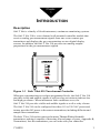
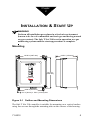
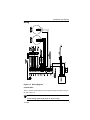
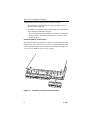
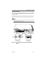
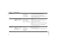
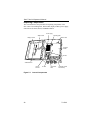
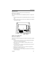
Safe T Net 210
Instruction Manual
Part Number 71-0012
31Mar2010
© 2007 Thermo Fisher Scientific Inc. All rights reserved.
Specifications, terms and pricing are subject to change. Not all products are available in all countries. Please
consult your local sales representative for details.
Thermo Fisher Scientific
Air Quality Instruments
27 Forge Parkway
Franklin, MA 02038
1-508-520-0430
www.thermo.com/aqi
WEEE Compliance
This product is required to comply with the European Union’s Waste
Electrical & Electronic Equipment (WEEE) Directive 2002/96/EC. It is
marked with the following symbol:
Thermo Fisher Scientific has contracted with one or more
recycling/disposal companies in each EU Member State, and this product
should be disposed of or recycled through them. Further information on
Thermo Fisher Scientific’s compliance with these Directives, the recyclers
in your country, and information on Thermo Fisher Scientific products
which may assist the detection of substances subject to the RoHS Directive
are available at: www.thermo.com/WEEERoHS.
Thermo Fisher Scientific
WEEE Compliance
WARNING
THIS INSTRUMENT IS DESIGNED TO DETECT ONE OR MORE OF
THE FOLLOWING:
FLAMMABLE VAPORS, OXYGEN CONTENT, AND/OR TOXIC GAS AND TO
GIVE WARNING BEFORE THEY REACH HARMFUL CONDITIONS. IN ORDER
TO ENSURE THAT IT WILL WARN OF DANGEROUS CONCENTRATIONS, IT
IS ESSENTIAL THAT THE INSTRUCTIONS IN THIS MANUAL, PARTICULARLY
THOSE CONCERNING START UP , OPERATION , CALIBRATION , AND
MAINTENANCE, BE READ, UNDERSTOOD, AND FOLLOWED.
NOTATION CONVENTIONS
Notices are used in this operator's manual to alert you to hazardous conditions to person or instrument and to notify you of additional information.
This operator's manual uses the following notices.
WARNING
Notifies you of potential danger that can result in personal injury
or death.
CAUTION
Notifies you of potential damage to equipment.
NOTE
Notifies you of additional or critical information.
SERVICE LOCATIONS
For additional assistance, Environmental Instruments Division has service available from
exclusive distributors worldwide. Contact one of the phone numbers below for product
support and technical information or visit us on the web at www.thermo.com/aqi.
1-866-282-0430 Toll Free
1-508-520-0430 International
Warranty
Seller warrants that the Products will operate or perform substantially in
conformance with Seller's published specifications and be free from defects
in material and workmanship, when subjected to normal, proper and
intended usage by properly trained personnel, for the period of time set
forth in the product documentation, published specifications or package
inserts. If a period of time is not specified in Seller’s product
documentation, published specifications or package inserts, the warranty
period shall be one (1) year from the date of shipment to Buyer for
equipment and ninety (90) days for all other products (the "Warranty
Period"). Seller agrees during the Warranty Period, to repair or replace, at
Seller's option, defective Products so as to cause the same to operate in
substantial conformance with said published specifications; provided that
(a) Buyer shall promptly notify Seller in writing upon the discovery of any
defect, which notice shall include the product model and serial number (if
applicable) and details of the warranty claim; (b) after Seller’s review, Seller
will provide Buyer with service data and/or a Return Material
Authorization (“RMA”), which may include biohazard decontamination
procedures and other product-specific handling instructions; and (c) then,
if applicable, Buyer may return the defective Products to Seller with all
costs prepaid by Buyer. Replacement parts may be new or refurbished, at
the election of Seller. All replaced parts shall become the property of Seller.
Shipment to Buyer of repaired or replacement Products shall be made in
accordance with the Delivery provisions of the Seller’s Terms and
Conditions of Sale. Consumables, including but not limited to lamps,
fuses, batteries, bulbs and other such expendable items, are expressly
excluded from the warranty under this warranty.
Notwithstanding the foregoing, Products supplied by Seller that are
obtained by Seller from an original manufacturer or third party supplier are
not warranted by Seller, but Seller agrees to assign to Buyer any warranty
rights in such Product that Seller may have from the original manufacturer
or third party supplier, to the extent such assignment is allowed by such
original manufacturer or third party supplier.
In no event shall Seller have any obligation to make repairs, replacements
or corrections required, in whole or in part, as the result of (i) normal wear
and tear, (ii) accident, disaster or event of force majeure, (iii) misuse, fault
or negligence of or by Buyer, (iv) use of the Products in a manner for which
they were not designed, (v) causes external to the Products such as, but not
limited to, power failure or electrical power surges, (vi) improper storage
and handling of the Products or (vii) use of the Products in combination
with equipment or software not supplied by Seller. If Seller determines
that Products for which Buyer has requested warranty services are not
Thermo Fisher Scientific
Warranty
covered by the warranty hereunder, Buyer shall pay or reimburse Seller for
all costs of investigating and responding to such request at Seller's then
prevailing time and materials rates. If Seller provides repair services or
replacement parts that are not covered by the warranty provided in this
warranty, Buyer shall pay Seller therefor at Seller's then prevailing time and
materials rates. ANY INSTALLATION, MAINTENANCE, REPAIR,
SERVICE, RELOCATION OR ALTERATION TO OR OF, OR
OTHER TAMPERING WITH, THE PRODUCTS PERFORMED BY
ANY PERSON OR ENTITY OTHER THAN SELLER WITHOUT
SELLER'S PRIOR WRITTEN APPROVAL, OR ANY USE OF
REPLACEMENT PARTS NOT SUPPLIED BY SELLER, SHALL
IMMEDIATELY VOID AND CANCEL ALL WARRANTIES WITH
RESPECT TO THE AFFECTED PRODUCTS.
THE OBLIGATIONS CREATED BY THIS WARRANTY
STATEMENT TO REPAIR OR REPLACE A DEFECTIVE PRODUCT
SHALL BE THE SOLE REMEDY OF BUYER IN THE EVENT OF A
DEFECTIVE PRODUCT. EXCEPT AS EXPRESSLY PROVIDED IN
THIS WARRANTY STATEMENT, SELLER DISCLAIMS ALL
OTHER WARRANTIES, WHETHER EXPRESS OR IMPLIED, ORAL
OR WRITTEN, WITH RESPECT TO THE PRODUCTS,
INCLUDING WITHOUT LIMITATION ALL IMPLIED
WARRANTIES OF MERCHANTABILITY OR FITNESS FOR ANY
PARTICULAR PURPOSE. SELLER DOES NOT WARRANT THAT
THE PRODUCTS ARE ERROR-FREE OR WILL ACCOMPLISH
ANY PARTICULAR RESULT.
Warranty
Thermo Fisher Scientific
TABLE OF CONTENTS
Chapter 1
Introduction
Description . . . . . . . . . . . . . . . . . . . . . . . . . . . . . . . . . . . . . . . . . . . . . . 1
Features . . . . . . . . . . . . . . . . . . . . . . . . . . . . . . . . . . . . . . . . . . . . . . . . . 2
Accessories. . . . . . . . . . . . . . . . . . . . . . . . . . . . . . . . . . . . . . . . . . . . . . . 2
Specifications . . . . . . . . . . . . . . . . . . . . . . . . . . . . . . . . . . . . . . . . . . . . . 3
Chapter 2
Installation and Start Up
Mounting . . . . . . . . . . . . . . . . . . . . . . . . . . . . . . . . . . . . . . . . . . . . . . . . 5
Wiring . . . . . . . . . . . . . . . . . . . . . . . . . . . . . . . . . . . . . . . . . . . . . . . . . . 7
Programming . . . . . . . . . . . . . . . . . . . . . . . . . . . . . . . . . . . . . . . . . . . . 13
Start Up . . . . . . . . . . . . . . . . . . . . . . . . . . . . . . . . . . . . . . . . . . . . . . . . 23
Chapter 3
Normal Operation and Alarms
Normal Operation . . . . . . . . . . . . . . . . . . . . . . . . . . . . . . . . . . . . . . . . 25
Alarms . . . . . . . . . . . . . . . . . . . . . . . . . . . . . . . . . . . . . . . . . . . . . . . . . 25
Chapter 4
Calibration
Calibration Mode . . . . . . . . . . . . . . . . . . . . . . . . . . . . . . . . . . . . . . . . . 31
Chapter 5
Maintenance
Routine Maintenance . . . . . . . . . . . . . . . . . . . . . . . . . . . . . . . . . . . . . . 33
Interchangeability of Components . . . . . . . . . . . . . . . . . . . . . . . . . . . . 33
Troubleshooting . . . . . . . . . . . . . . . . . . . . . . . . . . . . . . . . . . . . . . . . . . 33
Replacing Components . . . . . . . . . . . . . . . . . . . . . . . . . . . . . . . . . . . . 36
Appendix A
Parts List . . . . . . . . . . . . . . . . . . . . . . . . . . . . . . . . . . . . . . . . . . . . . . . 43
Appendix B
Transmitters . . . . . . . . . . . . . . . . . . . . . . . . . . . . . . . . . . . . . . . . . . . . . 45
71-0012
ix
Chapter
1
INTRODUCTION
Description
Safe T Net is a family of fixed-instrument, continuous-monitoring systems.
The Safe T Net 210 is a two-channel wall-mounted controller module that
receives analog gas measurement signals from one or two remote gas
transmitters and displays the gas concentrations on two digital display
screens. In addition, the Safe T Net 210 provides two analog outputs
proportional to the gas measurement signals.
HIGH ALARM
LOW ALARM
FAULT
HIGH ALARM
LOW ALARM
FAULT
TYPE 210
GAS MONITOR
RESET
Figure 1-1 Safe T Net 210 Two-channel Controller
When gas concentrations exceed pre-programmed levels, the Safe T Net 210
provides visible and audible signals as well as relay activation to indicate low
and high gas alarms. When instrument fault conditions occur, the
Safe T Net 210 provides visible and audible signals as well as relay closure.
The Safe T Net 210 can be configured for either 115 or 230 VAC power and,
in turn, provides DC power to the remote transmitters, including diffusion and
sample-draw transmitters.
The Safe T Net 210 can be connected to many Thermo Fisher Scientific
transmitters, making it capable of detecting a broad range of gases. Appendix B,
Transmitters, lists the transmitters you can order with your controller.
71-0012
1
Safe T Net 210 Operator’s Manual
Features
• Accepts one or two channels of standard 4 to 20 mA analog input
signals from remote 2- or 3-wire transmitters for detecting
combustible gas, toxic gas, or oxygen concentrations.
• Simultaneously displays the current gas reading for both channels.
• Provides a 4 to 20 mA analog output for each channel.
• Warns you of hazardous gas concentration conditions with audible
and visual indications at two alarm setpoints for each channel.
• Provides a low and a high alarm relay for each channel.
• Fault circuit provides visual, audible, and relay indications to warn
you of detector failure or other malfunctions.
• Components are enclosed in a wall-mounted NEMA 4X housing.
Programmable Relay Operation
Each active channel has two relays: Low alarm and high alarm. A master fault
relay activates if either channel is in a fail condition. You can program the
relays for latching or self-resetting alarm logic, energizing or de-energizing
relay activation (low and high alarm relays), activation on rising or falling
signal levels, and time delay (0 to 30 seconds) to avoid false alarms due to
radio frequency interference (RFI) or electromagnetic interference (EMI).
Accessories
The standard and optional accessories for the Safe T Net 210 (see Appendix
A for parts numbers).
• Operators Manual (standard)
- Includes detailed installation, operation, maintenance, and
calibration procedures for the Safe T Net 210.
• AC line cord (optional)
- Three-conductor cable with reducer and cord grip for installation.
2
71-0012
Introduction
Specifications
Table 1-1 lists the specifications of the Safe T Net 210. See Appendix B,
Transmitters, for gas detection specifications.
Table 1-1
Safe T Net 210 Specifications
Range
Adjustable to 999. Decimal can be set in any position.
Analog signal inputs
Two 24 VDC, 4 to 20 mA analog input signals, sourcetype, two- or three-wire
Analog outputs
One 4 to 20 mA source for each channel,
1000 OHMS maximum @ 24 VDC input
Relay outputs
Low alarm relay (Form C) and high alarm relay (Form A)
for each channel, programmable for latching/non-latching,
and energized/de-energized. Common fault (Form B),
normally energized, programmable for latching/nonlatching. Each relay rated at 10 AMP/125 VAC.
AC power
Nominal: 115 VAC, 60 Hz (Tolerance: 85 to 132 VAC,
47-63 Hz) or 230 VAC, 60 Hz (Tolerance: 170 to 264
VAC, 47-63 Hz)
Current
consumption
0.4 Amp maximum
Fuses
AC fuse: GMA 2, 250 V/2 Amp (115V system)
AC fuse: SO-BLO, 250 Volts, 1 Amp (230V system)
DC fuse: 3AG-1, 250 V/1 Amp
Low alarms
- Independently adjustable from OFF to full scale
- Audible and visual indication
- Acknowledged using the RESET button
- Programmable to activate on rising or falling level
High alarms
- Independently adjustable from OFF to full scale
- Audible and visual indication
- Programmable to activate on rising or falling level
Common fault alarm
Programmable to activate at 3.7 mA, 3.2 mA, or 2.0 mA
input signal. Can be disabled. Factory setting: 3.7 mA.
Calibration time out
Programmable from 0 (no time out) to 99 minutes
Alarm delay
Programmable from 0 (no delay) to 30 seconds
Operating
temperature
-20° to +45°C (-5° to +115°F).
71-0012
3
Safe T Net 210 Operator’s Manual
Table 1-1
4
Safe T Net 210 Specifications
Operating humidity
0 to 100% RH non-condensing
Enclosure rating
NEMA 4X
Overall Dimensions
10.50” (267 mm) W, 12.50” (318 mm) H, 6.25” (159 mm) D
Weight
Approximately 8lbs (3.8 Kg)
Case material
Molded fiberglass polyester
Approvals
UL Classified, CSA certified (File No. LR60959-35C)
71-0012
Chapter
2
INSTALLATION & START UP
WARNING
Perform all installation procedures in a fresh air environment
(known to be free of combustible and toxic gas and having normal
oxygen content). The Safe T Net 210 is not in operation as a gas
monitoring system until the start-up procedure is complete.
Mounting
10.50 in (267 mm)
6.25 in (159 mm)
HIGH ALARM
LOW ALARM
FAULT
HIGH ALARM
LOW ALARM
FAULT
12.94 in
(329 mm)
TYPE 210
GAS MONITOR
RESET
8.00 in (203 mm)
O .31 in (8 mm) x .50 in (13 mm) slot
Figure 2-1 Outline and Mounting Dimensions
The Safe T Net 210 controller is suitable for mounting on a vertical surface
using four screws through the mounting tabs on the corners of the housing.
71-0012
5
Safe T Net 210 Operator’s Manual
CAUTION
The Safe T Net 210 is suitable for installation in a non-hazardous
environment (where general purpose equipment is used). The
Safe T Net 210 is not suitable for installation in Class I, Division 1,
or Division 2 areas.
1. Consider the following factors when you select the mounting site:
• The installation should be in a safe area, preferably near an entrance
door where the fire department or other emergency response team
can see the indication if an alarm has caused the building to be
evacuated.
• AC power must be available.
• Provide room to open the housing door.
• Provide room to make wiring connections through the conduit
hubs.
2. Close and latch the housing door.
3. Position the Safe T Net 210 on a vertical surface at eye level
(approximately 5 feet (1.5 m) above the floor).
4. Secure the housing to the vertical surface with one 1/4 inch screw
through each mounting tab.
6
71-0012
Installation and Start Up
Wiring
Figure 2-2 Wiring Diagram
Conduit Hubs
Three 3/4" NPT conduit hubs provide routing for input and output wiring to
the Safe T Net 210.
CAUTION
Isolate analog signal wiring from AC power wiring.
71-0012
7
Safe T Net 210 Operator’s Manual
A typical Safe T Net 210 wiring scheme is arranged as follows:
• The incoming AC wiring and the relay output wiring are routed
through the left conduit hub.
• The channel 1 and channel 2 input/output wiring is routed through the
center and right conduit hubs, including:
- Power and signal leads to the channel 1 and channel 2 transmitters
- Analog outputs to the channel 1 and channel 2 recorders or other
monitoring devices
Controller Module Terminal Strip
The controller module terminal strip is composed of three connectors of nine
terminals each. The connectors can be removed to facilitate installation and
service operations and keyed to prevent them from being interchanged. The
27 screw-type terminals accept wire up to 12 gauge.
1 2 3 4
5
6 7 8
9 10 11 12
13 14 15
16 17 18
19 20 21 22
23 24 25 26
27
Figure 2-3 Controller Circuit Board Terminal Strip
8
71-0012
Installation and Start Up
Table 2-1
Safe T Net 210 Terminal Strip
Terminal
Label
Terminal
Number
Description
NC
COM
T27
T26
Normally closed 1
Common
Common fault relay
NO
COM
T25
T24
Normally open 2
Common
Channel 2
high alarm relay
NO
COM
T23
T22
Normally open 2
Common
Channel 1
high alarm relay
NO
COM
NC
T21
T20
T19
Normally open
Common
Normally closed
Channel 2
low alarm relay
NO
COM
NC
T18
T17
T16
Normally open
Common
Normally closed
Channel 1
low alarm relay
+
-
T15
T14
4 to 20 mA
Common
Channel 2
4 to 20 mA analog
output signal
+
-
T13
T12
4 to 20 mA
Common
Channel 1
4 to 20 mA analog
output signal
FB
+
T11
T10
T9
Common
Signal
+24 VDC
Channel 2
4 to 20 mA analog
input signal
SHIELD
T8
Shield
FB
+
T7
T6
T5
Common
Signal
+24 VDC
RESET
T4
External RESET button
GND
COM
24 VDC
T3
T2
T1
Ground (chassis)
Common (circuit ground)
+24 VDC
Channel 1
4 to 20 mA analog
input signal
Power in
1. The fault relay is normally energized and de-energizes in a fault condition such that
contact closure occurs between C and NC in a fault condition.
2. Can be factory configured to be normally closed and open on alarm.
71-0012
9
Safe T Net 210 Operator’s Manual
Connecting the Transmitters
The Safe T Net 210 controller can be used with any two standard 2- or 3-wire
4 to 20 mA analog transmitters. See the transmitter manual for wiring
instructions. When changing transmitter types, see the Programming section
of this chapter for Safe T Net 210 programming instructions.
Connecting External Alarm Devices
CAUTION
External alarms are controlled by the alarm relays. The relays are
rated for 10 Amps maximum. Do not connect any device with a
current load that exceeds the limit of the relay.
1. Run the external alarm wires through the left conduit hub.
2. Connect the external alarm wires to the controller module terminal
strip as shown in Figure 2-2. Terminals 16 through 25 pertain to the
channel 1 and channel 2 low and high gas alarm relays.
• Connect the positive or hot wire of the external power source to the
C (common) terminal of the corresponding relay.
• Connect the positive or hot wire of the external alarm device to the
NC (normally closed) or NO (normally open) terminal of the
corresponding relay, as appropriate.
• Connect the negative or neutral lead of the external power source to
the negative or neutral lead of the alarm device.
NOTE
The low and high alarm relays are factory set to be deenergized in
normal operation, and to energize when the Safe T Net 210 is in alarm
condition. Each alarm relay can be individually reprogrammed to
energize in normal condition and de-energize when an alarm occurs.
To reprogram the alarm relays, use the U9 and U10 DIP switch
settings described in the Changing the Settings section in this chapter.
The common fault relay is energized in normal operation and deenergizes when the Safe T Net 210 is in fault condition. The fault
relay cannot be programmed for normally de-energized operation.
NO (normally open) and NC (normally closed) describe the condition
of the relay when it is de-energized. If the relay is energized in normal
operation, NC is open and NO is closed.
10
71-0012
Installation and Start Up
Wiring the Analog Outputs
1. Run the analog output leads through the selected conduit hubs (not the
same conduit hub as the AC wiring and the external alarm wires).
2. Connect the analog output leads to the controller circuit board terminal
strip as shown in Figure 2-2. Terminals 12 through 15 pertain to the
channel 1 and channel 2 analog output signals.
• Connect the positive lead of the external monitoring device to the
positive (+) terminal of the output signal for that channel.
• Connect the negative lead of the external monitoring device to the
negative (–) terminal of the output signal for that channel.
CAUTION
The maximum input impedance of the monitoring device must not
exceed 1,000 ohms.
Wiring AC Power
The Safe T Net 210 operates from either 115 or 230 VAC power.
WARNING
Verify that the AC power you are using matches the power supply
installed in the Safe T Net 210. Refer to the Controller Module
label for verification.
WARNING
Make all of the internal connections before you turn on the
AC power. Always turn off the AC power before making any
wiring changes.
1. Run the optional AC line cord assembly or other AC power line
through the left conduit hub.
2. Connect the incoming AC leads to terminals L, N, and G of the
AC terminal block (see Figure 2-4):
• Connect the line (“hot”, black) lead to L.
• Connect the neutral (white) lead to N.
• Connect the ground (green) lead to G.
71-0012
11
Safe T Net 210 Operator’s Manual
3. The wiring between the AC terminal block and the power supply is
installed at the factory. This information is included in case the power
supply needs to be replaced.
• The black lead goes from the L terminal of the AC terminal block
to the L terminal of the power supply.
• The white lead goes from the N terminal of the AC terminal block
to the N terminal of the power supply.
• The green lead goes from the G terminal of the AC terminal block
to the large ground terminal next to the power supply.
POWER SUPPLY
CONTROLLER MODULE
+V O FG L
N
WHITE
ORANGE
BLACK
RED
GREEN (2)
1 2 3 4
BLACK
Factory wiring
Customer wiring
GROUND
NEUTRAL
LINE
VAC
Figure 2-4 AC and DC Power Wiring
12
71-0012
Installation and Start Up
Wiring DC Power
The DC power wiring between the AC terminal block, the power supply, and
the controller module is installed at the factory. This information is included
in case the power supply or the controller need to be replaced.
Connect the DC leads between the power supply and terminals 1 through 3 of
the controller module (see Figure 2-4):
1. Connect the positive (+) lead from power supply terminal +V to
controller terminal 1 (24VDC).
2. Connect the negative (–) lead from power supply terminal O to
controller terminal 2 (COM).
3. Connect the ground lead from power supply terminal FG to controller
terminal 3 (GND).
Programming
The Safe T Net 210 can be programmed for any gas detection application
supported by the 4 to 20 mA transmitters listed in Appendix B, Transmitters.
Using the programming switches and buttons along the edge of the controller
module circuit board, you can set the following parameters for each channel:
• Channel settings:
-
Range
Decimal place
Indicated gas units (PPM, %LEL, %VOL)
Low and high alarm levels
• Gas alarm relays:
- Latching or self-resetting
- Normally energized or de-energized
- Activated on rising or falling level
• Fault alarm:
- Activation level
- Relay latching or self-resetting
• Alarm buzzer enabled or disabled
• Calibration time out
• Alarm delay
71-0012
13
Safe T Net 210 Operator’s Manual
Standard Settings
Table 2-2
Standard Factory Settings
Low Alarm
Form C
Normally de-energized
Latching (O2 alarms are self-resetting.)
Activated on a rising concentration (O2 low alarm is
activated on a falling concentration.)
High Alarm
Form A
Normally de-energized
Latching (O2 alarms are self-resetting.)
Activated on a rising concentration
Fault Alarm
Form B
Normally energized
Self-resetting
Fault alarm setpoint: 3.7 mA analog input signal
Alarm Delay
One second
Calibration
time out
15 minutes
Buzzer
Enabled
The standard ranges for various transmitter types are listed in Appendix B,
Transmitters.
CAUTION
The standard ranges provide optimum performance of each
transmitter type. Contact Thermo Fisher Scientific before
using a non-standard range.
14
71-0012
Installation and Start Up
Changing the Settings
The settings are made using the three DIP switches (U1, U9, U10) and three
buttons, STEP, s (UP), and t (DOWN), located at the edge of the controller
module circuit board.
On the DIP switches, ON is the switch position to the right (away from the
edge of the board) and OFF is to the left (toward the edge of the board).
NOTE
While the Safe T Net 210 is in any of its set-up modes, the 4 to 20 mA
analog output signals fall to 1.5 mA.
DC fuse
UP
DOWN
STEP
Control buttons
DIP switches
Figure 2-5 Controller Board Switches and Programming
Buttons
71-0012
15
Safe T Net 210 Operator’s Manual
DIP SWITCH U1 (COMMON SETTINGS)
U1 is the DIP switch closest to the top of the module (adjacent to the control
buttons). The switches of U1 control the settings common to both channels.
Table 2-3
Switch
Position
Function
1 (top)
ON
Enable set-up mode 1 for both channels. See
Set-up Mode 1 in this chapter.
OFF
Normal operation
ON
Enable set-up mode 2 for both channels. See
Set-up Mode 2 in this chapter.
OFF
Normal operation
ON
Enable set-up mode 3 for both channels. See
Set-up Mode 3 in this chapter.
OFF
Normal operation
ON
Select channel 1 (set-up mode 3)
OFF
Select channel 2 (set-up mode 3)
ON
Fault relay latched
OFF
Fault relay unlatched (self-resetting)
2
3
4
5
6
7
8
(bottom)
16
DIP switch U1 - Settings Common to Both Channels
Switches 6 and 7 are used together to set the fault alarm
setpoint.
See Fault Alarm Setpoint in this chapter.
ON
Enable alarm buzzer
OFF
Disable alarm buzzer
71-0012
Installation and Start Up
DIP SWITCH U9 (CHANNEL 1 RELAYS)
U9 is the middle of the three DIP switches. The switches of U9 control the
operation of the channel 1 low and high relays. Switch 7 turns channel 1 on
and off.
Table 2-4
DIP switch U9 - Channel 1 Settings
Switch
Position
Function
1 (top)
ON
Channel 1 low relay latched
OFF
Channel 1 low relay unlatched (selfresetting)
ON
Channel 1 low relay normally de-energized
OFF
Channel 1 low relay normally energized
ON
Channel 1 low relay activated on falling level
OFF
Channel 1 low relay activated on rising level
ON
Channel 1 high relay latched
OFF
Channel 1 high relay unlatched (selfresetting)
ON
Channel 1 high relay normally de-energized
OFF
Channel 1 high relay normally energized
ON
Channel 1 high relay activated on falling
level
OFF
Channel 1 high relay activated on rising level
ON
Channel 1 OFF 1
OFF
Channel 1 ON
OFF
Must be set to OFF only
2
3
4
5
6
7
8 (bottom)
1. When channel 1 is off, the display shows OFF, the status LEDs (HIGH ALARM,
LOW ALARM, and FAULT) are off, the relays are held in the inactive state, the
analog output is 0 mA, and the channel cannot be placed in calibration mode.
71-0012
17
Safe T Net 210 Operator’s Manual
DIP SWITCH U10 (CHANNEL 2 RELAYS)
U10 is the bottom DIP switch (closest to the fuse). The switches of U10
control the operation of the channel 2 low and high relays. Switch 7 turns
channel 2 on and off.
Table 2-5
DIP switch U10 - Channel 2 Settings
Switch
Position
Function
1 (top)
ON
Channel 2 low relay latched
OFF
Channel 2 low relay unlatched (selfresetting)
ON
Channel 2 low relay normally de-energized
OFF
Channel 2 low relay normally energized
ON
Channel 2 low relay activated on falling level
OFF
Channel 2 low relay activated on rising level
ON
Channel 2 high relay latched
OFF
Channel 2 high relay unlatched (selfresetting)
ON
Channel 2 high relay normally de-energized
OFF
Channel 2 high relay normally energized
ON
Channel 2 high relay activated on falling
level
OFF
Channel 2 high relay activated on rising level
ON
Channel 2 OFF 1
OFF
Channel 2 ON
OFF
Must be set to OFF only
2
3
4
5
6
7
8 (bottom)
1. When channel 2 is off, the display shows OFF, the status LEDs (HIGH ALARM,
LOW ALARM, and FAULT) are off, the relays are held in the inactive state, the
analog output is 0 mA, and the channel cannot be placed in calibration mode.
18
71-0012
Installation and Start Up
SET-UP MODE 1 (RANGES AND ALARM SETPOINTS)
Set-up mode 1 is used to set the following range and alarm levels for channel
1 and channel 2.
• Channel 1 range, low alarm, and high alarm
• Channel 2 range, low alarm, and high alarm
CAUTION
The standard ranges are listed in Appendix B, Transmitters of the
Safe T Net 210 Operator’s Manual provide optimum performance
of each transmitter type. Contact Thermo Fisher Scientific
before using a non-standard range.
You can exit set-up mode 1 by setting switch 1 to OFF at any point during
the procedure without losing your settings. In addition, range and alarm
settings are retained by the Safe T Net 210 even when power is removed.
While the Safe T Net 210 is in set-up mode 1, both 4 to 20 mA analog
outputs go to 1.5 mA.
1. Initiate set-up mode 1 by placing U1 switch 1 in the ON position (away
from the edge of the board).
2. The channel 1 display, LOW ALARM LED, and HIGH ALARM LED
flash. Channel 1 range cannow be set using the s (UP) andt (DOWN)
buttons.
3. Press the STEP button to accept the desired value and go to the next
setting.
4. The channel 1 display and LOW ALARM LED flash. Channel 1 low
alarm level can now be set using the s (UP) and t (DOWN) buttons.
5. Press the STEP button to accept the desired value and go to the next
setting.
6. The channel 1 display and HIGH ALARM LED flash. Channel 1 high
alarm level can now be set using the s (UP) and t (DOWN) buttons.
7. Press the STEP button to accept the current value and go to the next
setting.
8. The channel 2 display, LOW ALARM LED, and HIGH ALARM LED
flash. Channel 2 range cannow be set using the s (UP) andt (DOWN)
buttons.
9. Press the STEP button to accept the desired value and go to the next
setting.
10. The channel 2 display and LOW Alarm LED flash. Channel 2 low
alarm level can now be set using the s (UP) and t (DOWN)
buttons.
71-0012
19
Safe T Net 210 Operator’s Manual
11. Press the STEP button to accept the desired value and go to the next
setting.
12. The channel 2 display and HIGH ALARM LED flash. Channel 2 high
alarm level can now be set using the s (UP) and t (DOWN)
buttons.
13. Return U1 switch 1 to OFF to resume normal operation.
SET-UP MODE 2 (GAS UNITS AND DECIMAL PLACE)
Set-up mode 2 is used to set the following parameters individually for
channel 1 and channel 2.
• Channel 1 decimal place
• Channel 1 indicated gas units (PPM, %LEL, %VOL)
• Channel 2 decimal place
• Channel 2 indicated gas units (PPM, %LEL, %VOL)
You can exit set-up mode 2 by setting switch 2 to OFF at any point during
the procedure without losing your settings. In addition, decimal place and
gas unit settings are retained by the Safe T Net 210 even when power is
removed. While the Safe T Net 210 is in set-up mode 2, both 4 to 20 mA
analog outputs go to 1.5 mA.
1. Initiate set-up mode 2 by placing U1 switch 2 in the ON position (away
from the edge of the board).
2. The channel 1 display flashes, showing full scale range. The channel 1
decimal place can now be set using the s (UP) and t (DOWN)
buttons.
3. Press the STEP button to accept the desired value and go to the next
setting.
4. The channel 1 display shows only the decimalpoint chosen; the selected
gas units flash. The channel 1 gas units (PPM, %LEL, %VOL) can now
be set using the s (UP) and t (DOWN) buttons.
5. Press the STEP button to accept the desired value and go to the next
setting.
6. The channel 2 display flashes, showing full scale range. The channel 2
decimal place can now be set using the s (UP) and t (DOWN)
buttons.
7. Press the STEP button to accept the desired value and go to the next
setting.
8. The channel 2 display shows only the decimalpoint chosen; the selected
gas units flash. The channel 2 gas units (PPM, %LEL, %VOL) can now
be set using the s (UP) and t (DOWN) buttons.
9. Return U1 switch 2 to OFF to resume normal operation.
20
71-0012
Installation and Start Up
SET-UP MODE 3
Set-up mode 3 is a factory-only calibration that calibrates the signal input
circuitry to recognize the 0 mA and 20 mA analog inputs.
CAUTION
Set-up Mode 3 is a factory adjustment and is not generally meant
to be made by the user.
1. Initiate set-up mode 3 by placing U1 switch 3 in the ON position (away
from the edge of the board).
2. Select channel 1 (switch 4 = ON)
or channel 2 (switch 4 = OFF).
3. The selected display and status LEDs flash.
4. With no signal (0 mA) applied to the channel input terminals, press the
t (DOWN) button.
5. Apply 20.0 mA to the channel input terminals and press the s (UP)
button.
6. Return U1 switch 3 to OFF to resume normal operation.
While the Safe T Net 210 is in set-up mode 3, both 4 to 20 mA analog output
signals go to 1.5 mA.
FAULT ALARM SETPOINT
The Safe T Net 210 generates a fault alarm when either of the channel
analog input signals drops below the 4.0 mA analog input signal zero point
to the programmed fault alarm setpoint. The setting applies to both channel
inputs. When the fault alarm is triggered, the FAULT LED lights, the buzzer
sounds, and the fault relay de-energizes and the contacts close.
Set the fault alarm setpoint by setting U1 switches 6 and 7 as shown in
Table 2-6.
Table 2-6
Fault Alarm Trigger Levels
Fault Alarm Analog Input
Signal Setpoint
U1 Switch 6
U1 Switch 7
2.0 mA
OFF
ON
3.2 mA ON
3.7 mA (factory setting)
71-0012
OFF
ON
ON
21
Safe T Net 210 Operator’s Manual
CALIBRATION TIME-OUT MODE
If calibration time out mode is not turned off manually, the Safe T Net 210
automatically returns to normal operation from calibration mode after a
preprogrammed time from 0 (no time out) to 99 minutes.
NOTE
The standard calibration time out factory setting is 15 minutes.
Program the calibration time out as follows:
1. While in normal operation, press the STEP and t (DOWN) buttons
simultaneously to initiate the calibration time out setup mode.
2. The channel 1 LOW and HIGH ALARM LEDs are lit, the display
shows the current calibration time out setting in minutes. The
calibration time out can now be set using the s (UP) and t (DOWN)
buttons.
3. Press the STEP button to accept the desired value and resume normal
operation.
CAUTION
The visual and audible alarm indications and relays are inactive
during calibration time out and will not indicate any hazardous
gas concentrations that may occur while calibration mode is
enabled.
22
71-0012
Installation and Start Up
ALARM DELAY
The Safe T Net 210 can be programmed to delay the operation of alarm
relays and status LEDs for a pre-determined time after alarm levels have
been exceeded. This feature prevents nuisance alarms caused by transient
radio frequency interference (RFI). The alarm delay can be set from 0 (no
delay) to 30 seconds.
NOTE
The standard alarm delay factory setting is one second.
WARNING
Audible and visible alarm indicators are not active, and relays not
activated, for the length of the alarm delay.
Set the alarm delay as follows:
1. While in normal operation, press the s (UP) and t (DOWN) buttons
simultaneously to initiate the alarm delay set-up mode.
2. The channel 1 display shows the current alarm delay in seconds. The
alarm delay can now be set using the s (UP) and t (DOWN) buttons.
3. Press the STEP button to accept the desired value and resume normal
operation.
Start-Up
Complete the following procedures to place the Safe T Net 210 in normal
operation.
Preparing for Start Up
1. Complete the mounting and wiring procedures described earlier in this
chapter.
2. Complete all installation procedures described in the Transmitters
manual.
3. Verify that all wiring connections are correct and secure.
Introducing Power
Turn on the incoming power at the power source.
NOTE
The low alarm, high alarm, and fault circuits are not active for
1 minute after power is applied to the Safe T Net 210. This time delay
minimizes false alarms during transmitter warm-up.
71-0012
23
Safe T Net 210 Operator’s Manual
Verifying Indicator Lights
1. Verify that the displays are on.
2. If no light comes on during the start-up sequence, the Safe T Net 210 is
not receiving power. Check the wiring connection, the power source,
and the fuses. See Chapter 5, Maintenance, for detailed
troubleshooting instructions.
3. Table 2-7 lists the conditions indicated by the status indicator lights
during start up and the suggested response for each condition.
Table 2-7
Start Up Indications
Indicators
Probable Status
Recommended Response
Displays and
other lights on.
Receiving power.
None
FAULT LED on.
Below-zero reading.
1. Allow the transmitter to warm-up.
2. Zero the transmitter output.
3. Replace detector if the below-zero
reading continues.
4. See the Troubleshooting section of
Chapter 5, Maintenance.
Detector, transmitter, 1. Verify transmitter and detector
wiring is correct and secure.
or circuitry is
broken, incomplete, 2. See the Troubleshooting section of
or incorrect.
the Transmitters manual.
ALARM LED on. Above-zero reading
1. Zero detector after warm up.
All displays and
LEDS off.
1. Check AC and DC fuses and power
wiring.
No power
Start up is complete, and the Safe T Net 210 is operating in normal mode.
24
71-0012
Chapter
3
NORMAL OPERATION AND ALARMS
Normal Operation
Normal operation is any time the start-up procedure is complete, no
calibration or set-up procedures are in progress, and no alarm, or fault
condition exists. During normal operation, the Safe T Net 210 behaves as
follows:
• The display screens display the current gas concentrations
(channel 1 on the top screen, channel 2 on the bottom screen).
• The 4 to 20 mA analog output signals at the terminal strip
(terminals 12 and 13 for channel 1, 14 and 15 for channel 2)
correspond to the displayed gas readings.
• The HIGH ALARM, LOW ALARM, and FAULT lights and relays
for both channels are deactivated.
Alarms
This section describes the Safe T Net 210 indications for low alarm, high
alarm, and fault conditions, including the standard relay action.
The Safe T Net 210 activates visual, audible, and relay alarm indications
when any of the programmed alarm setpoints are passed.
WARNING
The calibration mode feature of the Safe T Net 210 allows you to
disable the alarm LED’s, buzzer, and relays during calibration
procedures and response tests. When calibration mode is
activated, the LED’S, buzzer, and relays will not operate as
described in this section.
• Table 3-1 lists the Safe T Net 210’s alarm indications. The table
shows Thermo Fisher Scientific standard settings for alarm action
and relay activation.
• The Standard Range and Alarm Setpoint tables in each transmitter
manual lists the standard low and high alarm setpoints for the
transmitters supplied with your Safe T Net 210.
• You can adjust the relay action using the setup modes described in
Chapter 2, Installation and Start Up.
71-0012
25
Safe T Net 210 Operator’s Manual
Table 3-1
Audible and Visual Alarm Indications
Condition
Cause
Visual
Indication
Buzzer, if
activated
Normal
Start up complete; no gas
alarm or fault conditions.
Displays on
None
Low Alarm
Increasing reading at or
above low alarm setpoint.
LOW ALARM
LED on
Pulsing
Low Alarm
Decreasing O2 reading at or LOW ALARM
(Oxygen channel) below low alarm setpoint.
LED on
Pulsing
High Alarm
Increasing reading at or
above high alarm setpoint.
HIGH ALARM
LED on
Pulsing
Fault
Incomplete, broken, or
incorrect detector,
amplifier, or circuitry;
Below zero analog input
signal from transmitter.
FAULT LED
on; gas reading
alternates with
FLt
Pulsing
Low Alarm
When the displayed gas concentration passes the programmed low alarm
setpoint:
• The LOW ALARM LED lights.
• The buzzer pulses.
• The low alarm relay activates.
If the alarm is set to trigger on a rising level, the indications continue, unless
reset, until the concentration decreases below the setpoint.
If the alarm is set to trigger on a falling level, the indications continue, unless
reset, until the concentration increases above the setpoint.
RESET: Press the RESET button on the bottom of the housing to reset the
alarm. This causes the low alarm relay to deactivate and the buzzer to
silence. The LOW ALARM LED continues to flash until the alarm condition
passes.
Thermo Fisher Scientific sets the low alarm set points (except oxygen) for
latching action. Oxygen channel low alarms are factory programmed to be
self-resetting. You can select latch or self-reset alarm action in the setup modes
described in Chapter 2, Installation and Start Up.
26
71-0012
Normal Operation and Alarms
If the low alarm is latching: If the low alarm has been configured to be
latching, and the alarm has not been acknowledged, the buzzer, LED and
relay remain active after the alarm condition has passed. These alarm
indications must then be cleared by pressing the RESET button on the
bottom of the housing.
1. Follow the established procedure for a low level combustible or toxic
gas condition (or a decreasing oxygen condition). If a procedure is not
in place, establish one that is appropriate for your application.
2. When the reading returns to normal, press the RESET button to
silence the buzzer, turn off the LOW ALARM light, deactivate the
alarm relay, and reset the alarm circuit.
If the low alarm is self-resetting:
1. Follow the established procedure for a low level combustible or toxic
gas condition or a decreasing oxygen condition. If a procedure is not
in place, establish one that is appropriate for your application.
2. After the reading returns to normal, the Safe T Net 210 automatically
silences the buzzer, turns off the LOW ALARM light, deactivates the
applicable alarm relay, and resets the alarm circuit.
High Alarm
When the display level passes the programmed high alarm setpoint:
• The HIGH ALARM LED lights.
• The buzzer continues to pulse.
• The high alarm relay activates.
If the alarm is set to trigger on a rising concentration, the indications
continue until the reading decreases below the setpoint and, if the alarm is
latching, the RESET button is pressed.
If the alarm is set to trigger on a falling concentration, the indications
continue until the reading increases above the setpoint and, if the alarm is
latching, the RESET button is pressed.
NOTE
Unlike the low alarm, you cannot reset the high alarm while the
reading is at or above the high alarm set point.
Thermo GasTech sets the high alarms (except oxygen) for latching alarm
action. Oxygen channel high alarms are factory-programmed to be selfresetting. You can select latch or self-reset alarm action in the Setup modes
described in Chapter 2, Installation and Start Up.
71-0012
27
Safe T Net 210 Operator’s Manual
If the high alarm is latching: If the high alarm has been configured to be
latching, the buzzer, LED, and relay remain active after the alarm condition
has passed. The high alarm indications can only be cleared by pressing the
RESET switch on the bottom of the housing.
1. Follow the established procedure for a high level combustible, toxic,
or oxygen gas condition. If a procedure is not in place, establish one
that is appropriate for your application.
NOTE
You cannot silence the buzzer while the Safe T Net 210 is in a high
alarm condition. The reading must decrease below the high alarm
setpoint before you can silence the buzzer.
2. After the reading decreases below the high alarm setpoint, press the
RESET button to turn off the HIGH ALARM light, deactivate the
alarm relay, and reset the alarm circuit.
If the high alarm is self-resetting:
1. Follow the established procedure for a high level combustible, toxic,
or oxygen gas condition. If a procedure is not in place, establish one
that is appropriate for your application.
NOTE
You cannot silence the buzzer while the Safe T Net 210 is in a high
alarm condition. The reading must decrease below the high alarm
setpoint before you can silence the buzzer.
2. After the reading decreases below the high alarm setpoint, the
Safe T Net 210 automatically turns off the HIGH ALARM light, deenergizes the high alarm relay, and resets the high alarm circuit.
3. When the reading decreases below the high alarm setpoint, the
Safe T Net 210 may still be in low alarm condition. Respond to the
low alarm condition as appropriate.
28
71-0012
Normal Operation and Alarms
Fault Condition
The fault alarm is activated when the 4 to 20 mA analog input from a
transmitter falls below the 4 mA zero point to the programmed fault alarm
setpoint. This can be caused by such factors as a drifting sensor input or a
broken wire connection. When a fault alarm occurs, the indications are as
follows:
• The FAULT LED lights.
• The display alternates between the gas reading and FLt.
• The buzzer and fault relay activate.
The fault relay is programmable to be latching or self-resetting. The fault
relay is normally energized and de-energizes in fault condition.
The fault alarm setpoint can be changed using the programming controls.
See the Fault Alarm Level section of Chapter 2, Installation and Start Up.
If a fault condition occurs:
1. Make sure the wiring connections at the Safe T Net 210 terminal strip
are correct and secure.
2. See the Troubleshooting section in Chapter 5, Maintenance.
71-0012
29
Safe T Net 210 Operator’s Manual
30
71-0012
Chapter
4
CALIBRATION
No calibration of the Safe T Net 210 controller is required. Refer to the
transmitter manual for instructions on setting the analog output signal from
the transmitter.
Calibration Mode
To avoid unwanted alarms during the calibration procedure, either or both of
the channels of the Safe T Net 210 can be placed in calibration mode. In
calibration mode, the alarm LEDs and relays of the channel remain inactive,
the buzzer remains off, and the analog output signal goes to 1.5 mA.
Activate calibration mode by pressing the CALIBRATE button through the
opening marked CALIBRATE on the display module cover plate inside the
housing door.
If you do not turn off calibration manually, it will turn off automatically when
the calibration time-out has elapsed (standard factory setting is 15 minutes).
See the Calibration Time Out section of Chapter 2, Installation and Start Up,
for programming instructions.
CAUTION
The visual and audible alarm indications and relays are inactive
during calibration time out and will not indicate any hazardous
gas concentrations that may occur while calibration mode is
enabled.
Calibration mode has four settings (see Table 4-1).
Table 4-1
Calibration Mode Settings
CALIBRATE
button
Channel 1
Status
Channel 2
Status
Press 1 time
Calibration mode
Normal operation
Press 2nd time
Calibration mode
Calibration mode
Press 3rd time
Normal operation
Calibration mode
Press 4th time
Normal operation
Normal operation
71-0012
31
Safe T Net 210 Operator’s Manual
1. Pressing the CALIBRATE button the first time puts channel 1 only
into calibration mode:
• The display for channel 1 flashes, alternating the gas reading with
CAL.
• Channel 1 LOW, HIGH, and FAULT LEDs flash.
• The channel 1 relays remain inactive and the analog output signal
goes to 1.5 mA.
• Channel 2 remains in the normal monitoring mode.
• The display for channel 1 can now exceed the alarm levels without
activating the channel 1 alarm relays.
2. Pressing the CALIBRATE button a second time puts both channels
into calibration mode:
• The displays for both channels flash, alternating the gas readings
with CAL.
• The LOW, HIGH, and FAULT LEDs for both channels flash.
• The relays for both channels remain inactive and both analog
output signals go to 1.5 mA.
• The display for either or both channels can now exceed the alarm
levels without activating the alarm relays.
3. Pressing the CALIBRATE button a third time returns channel 1 to the
normal operation and puts channel 2 into calibration mode:
• The display for channel 2 flashes, alternating the gas reading with
CAL.
• The channel 2 LOW, HIGH, and FAULT LEDs flash.
• The channel 2 relays remain inactive and the analog output signal
falls to 1.5 mA.
• Channel 1 remains in the normal monitoring mode.
• The display for channel 2 can now exceed the alarm levels without
activating the channel 2 alarm relays.
4. Pressing the CALIBRATE button a fourth time returns both channels
to normal operation.
32
71-0012
Chapter
5
MAINTENANCE
WARNING
Perform all maintenance procedures described in this chapter in a
non-hazardous environment.
Routine Maintenance
Routine maintenance of the Safe T Net 210 consists only of periodic checks
to ensure that the system remains on zero (20.9% for O2) and is responsive to
gas. The transmitters used with the Safe T Net 210 must be calibrated at
regular intervals following the procedures described in the transmitter inserts.
Interchangeability of Components
The Safe T Net 210 controller can be used with any standard 2- or 3-wire
4 to 20 mA analog transmitter. When changing transmitter types, it may be
necessary to change the range, decimal point, and alarm setpoints for the
affected channel. Follow the instructions for programming the
Safe T Net 210 in Chapter 2, Installation and Start Up.
Troubleshooting
This troubleshooting guide describes symptoms, probable causes, and
recommended actions for problems you may encounter with the
Safe T Net 210 (refer to Table 5-1). This guide covers the Safe T Net 210
only, see the Troubleshooting section in the Transmitters manual, for
problems you may encounter with the transmitters.
71-0012
33
34
Problem
No Display or
Lights
Troubleshooting
Symptoms
No readings or message on
the display screens and no
indicator lights.
Probable Cause
• Incomplete or incorrect
power circuit.
• Poorly connected or
failed power supply.
• Failed AC or DC fuse.
• Poorly connected or
failed controller module.
• Poorly connected or
failed display.
• Poorly connected or
failed ribbon cable.
Recommended Action
1. Verify that AC power is on.
2. Verify correct connections at the AC power source.
3. Verify that the wiring connections at the AC terminal block
and the power supply are complete and correct.
4. Check that the display cable connections are secure.
5. Check the continuity of the AC fuse located at the AC
terminal block, and replace if necessary.
6. Check the continuity of the DC fuse located on the controller
module, and replace if necessary.
7. Check the AC voltage between the black and white wires at
the connection block. If the voltage is incorrect or not present,
troubleshoot the external AC power source.
8. Check the DC voltage at terminals 1 and 2 of the controller
module. If the voltage is not within the range 23 to 25 V,
replace the power supply.
9. If there is still no display, replace the ribbon cable.
71-0012
10. If there is still no display, replace the display module
11. If there is still no display, replace the controller module.
12. If power failure symptoms continue, contact Thermo
Fisher Scientific for further instruction.
Safe T Net 210 Operator’s Manual
Table 5-1
71-0012
Table 5-1
Frequent or
Suspect Alarms
Troubleshooting
Frequent or Suspect Alarms • False readings due to
radio frequency
interference (RFI) or
electromagnetic
interference (EMI).
1. Make sure that the transmitter wiring to the Safe T Net 210 is
properly shielded. See the Transmitter manual.
2. Increase the alarm delay setting using the set-up procedures
described in Chapter 2, Installation and Start Up.
3. If the alarm difficulties continue, contact Thermo Fisher
Scientific for further instructions.
1. Turn off calibrate mode as described in Chapter 4,
No Audible Alarm Buzzer does not sound
• Calibrate mode is on.
appropriate audible alarm. • Buzzer is disabled.
Calibration.
Audible alarm sounds weak
2.
Enable the buzzer. See the DIP switch U1 section of
• Buzzer is disconnected.
or broken.
Chapter 2, Installation and Start Up.
• Buzzer is malfunctioning.
3. Check the buzzer plug-in connection on the controller circuit
•
board.
4. Check that the screw connections on the buzzer are secure.
5. If the buzzer continues to fail, contact Thermo Fisher
Scientific for further instruction.
Incorrect Displays Letters or numbers on the
or Indicators
display screens are missing
or distorted.
LED indicators do not light
up appropriately.
• Faulty ribbon cable or
connections.
• Faulty connections.
• Display module
malfunction.
1. Replace the ribbon cable.
2. Replace the display module.
3. Contact Thermo Fisher Scientific for further instruction.
Maintenance
35
Safe T Net 210 Operator’s Manual
Replacing Components
This section describes the procedures for replacing components of the
Safe T Net 210, including fuses, ribbon cable, display module, power supply,
controller circuit board, buzzer, and RESET button.
.
Power supply
Ribbon cable
Mounting plate
Ribbon cable
Display module
Controller
module
DC fuse
Calibrate button
Ground
terminal
Figure 5-1
36
AC fuse
AC terminal
block
Controller module
terminal strip
Internal Components
71-0012
Maintenance
Replacing Fuses
The Safe T Net 210 has two fuses, an AC fuse and a DC fuse.
REPLACING THE AC FUSE
The AC fuse is located inside AC terminal block position L. To replace the
AC fuse:
1. Pull back the hinged section of terminal block position L to reveal the
fuse.
2. Replace with the same type (see Parts List, Appendix A), and snap the
section back into place.
DC fuse
AC fuse
Figure 5-2 AC and DC Fuse
REPLACING THE DC FUSE
The DC fuse is located at the edge of the controller circuit board. To replace
the DC fuse:
1. Disconnect power to the Safe T Net 210 by pulling back the hinged
section of AC terminal block position L.
2. Remove the six screws holding the controller module cover and
remove the cover.
3. Locate the fuse on the controller circuit board and remove it from its
spring clips using a screwdriver.
4. Replace the fuse with the same type (see Parts List, Appendix A).
5. Reinstall the controller module cover.
6. Restart the Safe T Net 210 according to the instructions in the Start Up
section of Chapter 2.
71-0012
37
Safe T Net 210 Operator’s Manual
Replacing the Ribbon Cable
1. Make sure the AC power is turned off.
2. Remove the six screws holding the controller module cover and
remove the cover.
3. Unplug the ribbon cable from the controller circuit board and from the
display module.
4. Remove the four screws holding the mounting plate and tilt the top of
the plate down and forward out of the housing. This reveals the entire
ribbon cable and the clips holding it in place. Do not remove the old
cable yet.
5. Observe exactly how the old cable is installed, including how the cable
is folded and how the cable is fitted into the clips.
6. Hold the new cable up to the old one and fold the new cable to match
the folds in the old one.
7. Remove the old cable from the clips and install the new one in its place
8. Plug the new ribbon cable in to the display module.
9. Holding the ribbon cable connector out of the way, position the
mounting plate and fasten it to the housing using the four screws at the
corners.
10. Plug the new ribbon cable in to the controller circuit board.
11. Reinstall the cover on the controller module.
12. Restart the Safe T Net 210 according to the instructions in the Start Up
section of Chapter 2.
Replacing the Display Circuit Board
1. Make sure the AC power is turned off.
2. Unplug the ribbon cable from the display module.
3. Remove the screws holding the cover plate on the display module and
remove the cover plate.
4. Remove the screws holding the display circuit board in place and
remove the display circuit board.
5. Hold the new display circuit board in position against the mounting
blocks and fasten it in place using the screws.
6. Reconnect the ground lead in the same position.
7. Plug the ribbon cable in to the new display circuit board.
8. Reinstall the cover plate on the display module.
9. Restart the Safe T Net 210 according to the instructions in the Start Up
section of Chapter 2.
38
71-0012
Maintenance
Replacing the Power Supply
1. Make sure the AC power is turned off.
2. Remove the six screws holding the controller module cover and
remove the cover.
3. Unplug the ribbon cable from the controller circuit board.
4. Remove the four screws holding the mounting plate and tilt the top of
the plate down and forward out of the housing.
5. From the back of the mounting plate, remove the two screws holding
the power supply and remove the power supply.
6. Disconnect the AC and DC wires from the old power supply.
7. Connect the AC leads from the AC terminal block to the terminal strip
of the new power supply as follows:
• Find the black lead that is connected to the L terminal of the
AC terminal block and connect the free end to power supply
terminal L.
• Find the white lead that is connected to the N terminal of the
AC terminal block and connect the free end to power supply
terminal N.
• Find the green lead that is connected to the large ground terminal
on the mounting plate and connect the free end to the unlabeled
terminal of the power supply.
8. Connect the DC leads to the terminal strip of the new power supply as
follows:
• Find the red positive (+) DC lead that is connected to controller
terminal 1 and connect the free end to power supply terminal +V.
• Find the black negative (–) DC lead that is connected to
controller terminal 2 and connect the free end to power supply
terminal O.
• Find the orange DC ground lead that is connected to controller
terminal 3 and connect the free end to power supply terminal
FG.
9. Hold the replacement power supply in position against the front of the
mounting plate and fasten it in place using the two screws through the
back of the mounting plate.
10. Position the mounting plate and fasten it to the housing using the four
screws at the corners.
11. Plug the ribbon cable into the controller circuit board.
12. Reinstall the cover on the controller module.
13. Restart the Safe T Net 210 according to the instructions in the Start Up
section of Chapter 2.
71-0012
39
Safe T Net 210 Operator’s Manual
Replacing the Controller Circuit Board
1. Make sure the AC power is turned off.
2. Unplug the three removable connectors from the controller module
terminal strip.
3. Remove the six screws holding the controller module cover and
remove the cover.
4. Record the position of the 24 DIP switches on the old controller
module to simplify setting the switches on the replacement module.
The ON position is away from the edge of the board, OFF is toward the
edge of the board.
5. Unplug the ribbon cable and the buzzer from the controller circuit
board.
6. Remove the four standoffs holding the controller circuit board in place
and lift the circuit board out of the housing.
7. Set the DIP switches on the replacement controller module to match
the settings on the old controller module.
8. Hold the replacement controller circuit board in position against the
mounting plate and fasten it in place using the four standoffs.
9. Plug the ribbon cable and the buzzer in to the new controller circuit
board.
10. Install the cover.
11. Plug the three connectors in to the new controller module terminal
strip. The connectors are keyed to preserve the proper order: Number
1 at the left, number 27 at the right.
12. Prepare the new controller module for your application according to
the instructions in the Programming and Start Up sections of
Chapter 2.
13. Restart the Safe T Net 210 according to the instructions in the Start Up
section of Chapter 2.
40
71-0012
Maintenance
Replacing the External Buzzer
1. Make sure the AC power is turned off.
2. Remove the two screws connecting the buzzer wires to the buzzer. If
necessary, loosen the plastic nut holding the external buzzer in the
housing and turn the buzzer for access to each screw.
3. Unscrew the plastic nut and pull the buzzer out through the hole.
4. Insert the replacement buzzer in through the hole. Screw the plastic nut
onto the threads of the buzzer but do not tighten it yet.
5. Connect the buzzer wires to the new buzzer using the two screws.
Connect the red wire to the positive (+) terminal of the buzzer, connect
the black wire to the negative (-) terminal of the buzzer.
6. Tighten the nut against the housing, securing the buzzer in place.
7. Restart the Safe T Net 210 according to the instructions in the Start Up
section of Chapter 2.
Replacing the RESET Button
1. Make sure the AC power is turned off.
2. Remove the two screws connecting the buzzer wires to the RESET
button. If necessary, loosen the nut holding the button in the housing
and turn the button for access to each screw.
3. Unscrew the nut and pull the button out through the hole.
4. Insert the replacement RESET button in through the hole. Screw the
nut onto the threads of the button but do not tighten it yet.
5. Connect the wires to the new button using the two screws.
6. Tighten the nut against the housing, securing the button in place.
7. Restart the Safe T Net 210 according to the instructions in the Start Up
section of Chapter 2.
71-0012
41
Safe T Net 210 Operator’s Manual
42
71-0012
Appendix
A
PARTS LIST
Table A-1
Safe T Net 210 Parts List
Part No.
Description
29-0018
Gas type labels, front panel (includes one label for each gas type)
43-0440
RESET switch
43-4140
DC fuse, 3AG-1, 250 Volts, 1 Amp
43-4232
AC fuse, SO-BLO, 250 Volts, 1 Amp (230V system)
43-4234
AC fuse, GMA2, 250 Volts, 2 Amp (115V system)
47-0003
Ribbon cable
47-1011
AC line cord, 3-conductor, with reducer and cord grip
49-0073
Power supply, 24 VDC 15W out, 115-230 VAC in
52-1016
External buzzer
57-0014-02
Display circuit board
57-0015-02
Controller circuit board
71-0012
Operator’s Manual, Safe T Net 210
73-0003
Safe T Net 210 two-channel wall-mounted controller, 115 VAC
73-0006
Safe T Net 210 two-channel wall-mounted controller, 230 VAC
71-0012
43
Safe T Net 210 Operator’s Manual
44
71-0012
Appendix
B
TRANSMITTERS
Each transmitter includes an manual describing the 4 to 20 mA analog gas
transmitters you ordered with your Safe T Net 210 gas monitoring controller.
A transmitter comes with the following:
• The transmitter assembly, including:
- Amplifier
- Housing
- Detector
• Transmitter Operator’s Manual
Various 4 to 20 mA analog gas transmitters are available from Thermo
Fisher Scientific for diffusion or sample-draw applications for most gases.
Diffusion transmitter part numbers have the 67- prefix and sample-draw
transmitter part numbers have the 68- prefix. Tables B-1 thru B-4 lists
the transmitters offered for the Safe T Net 210.
71-0012
45
Gas Type
Standard Transmitters for Safe T Net Controllers
71-0012
Part Number
Manual Insert P/N
Gas Transmitter
Detection Range
Ammonia (NH3)
67-0027-09
68-0020-09
71-0090
71-0114
Diffusion type
Sample draw
0 to 100 ppm
Arsine (AsH3)
67-0027-13
68-0020-13
71-0090
71-0114
Diffusion type
Sample draw
0 to 1 ppm
Carbon monoxide (CO)
67-0027-01
68-0020-01
71-0090
71-0114
Diffusion type
Sample draw
0 to 500 ppm
Chlorine (Cl2)
67-0027-04
68-0020-04
71-0090
71-0114
Diffusion type
Sample draw
0 to 10 ppm
Chlorine dioxide (ClO2)
67-0027-16
68-0020-16
71-0090
71-0114
Diffusion type
Sample draw
0 to 2 ppm
Combustible (LEL)
67-0007
68-0005
71-0024
71-0025
Diffusion type
Sample draw
0 to 100% LEL
Diborane (B2H6)
67-0027-18
68-0020-18
71-0090
71-0114
Diffusion type
Sample draw
0 to 1 ppm
Fluorine (F2)
67-0027-07
68-0020-07
71-0090
71-0114
Diffusion type
Sample draw
0 to 10 ppm
Hydrogen chloride (HCl)
67-0027-05
68-0020-05
71-0090
71-0114
Diffusion type
Sample draw
0 to 30 ppm
Hydrogen cyanide (HCN)
67-0027-08
68-0020-08
71-0090
71-0114
Diffusion type
Sample draw
0 to 50 ppm
Safe T Net 210 Operator’s Manual
46
Table B-1
71-0012
Table B-1
Gas Type
Standard Transmitters for Safe T Net Controllers (Continued)
Manual Insert P/N
Gas Transmitter
Detection Range
Hydrogen fluoride (HF)
67-0027-06
68-0020-06
71-0090
71-0114
Diffusion type
Sample draw
0 to 10 ppm
Hydrogen sulfide (H2S)
67-0027-02
68-0020-02
71-0090
71-0114
Diffusion type
Sample draw
0 to 100 ppm
Nitric oxide (NO)
67-0027-14
68-0020-14
71-0090
71-0114
Diffusion type
Sample draw
0 to 100 ppm
Nitrogen dioxide (NO2)
67-0027-15
68-0020-15
71-0090
71-0114
Diffusion type
Sample draw
0 to 20 ppm
Oxygen (O2)
67-0027-03
68-0020-03
71-0090
71-0114
Diffusion type
Sample draw
0 to 30% VOL
Ozone (O3)
67-0027-12
68-0020-12
71-0090
71-0114
Diffusion type
Sample draw
0 to 1 ppm
Phosphine (PH3)
67-0027-10
68-0020-10
71-0090
71-0114
Diffusion type
Sample draw
0 to 1 ppm
Silane (SiH4)
67-0027-11
68-0020-11
71-0090
71-0114
Diffusion type
Sample draw
0 to 20 ppm
Sulfur dioxide (SO2)
67-0027-17
68-0020-17
71-0090
71-0114
Diffusion type
Sample draw
0 to 20 ppm
47
Appendix B
Part Number
FX-SMT Transmitters for Safe T Net Controllers
Gas Type
Part Number
Manual Insert P/N
Gas Transmitter
Detection Range
Ammonia (NH3)
67-0024-09
71-0085
Diffusion type
0 to 100 ppm
Arsine (AsH3)
67-0024-13
71-0085
Diffusion type
0 to 1 ppm
Carbon monoxide (CO)
67-0024-01
71-0085
Diffusion type
0 to 500 ppm
Chlorine (Cl2)
67-0024-04
71-0085
Diffusion type
0 to 10 ppm
Chlorine dioxide (ClO2)
67-0024-16
71-0085
Diffusion type
0 to 2 ppm
Combustible (LEL)
67-0021-01
71-0085
Diffusion type
0-100% LEL
Diborane (B2H6)
67-0024-18
71-0085
Diffusion type
0 to 1 ppm
Fluorine (F2)
67-0024-07
71-0085
Diffusion type
0 to 10 ppm
Hydrogen chloride (HCl)
67-0024-05
71-0085
Diffusion type
0 to 30 ppm
Hydrogen cyanide (HCN)
67-0024-08
71-0085
Diffusion type
0 to 50 ppm
Hydrogen fluoride (HF)
67-0024-06
71-0085
Diffusion type
0 to 10 ppm
Hydrogen sulfide (H2S)
67-0024-02
71-0085
Diffusion type
0 to 100 ppm
Nitric oxide (NO)
67-0024-14
71-0085
Diffusion type
0 to 100 ppm
Nitrogen dioxide (NO2)
67-0024-15
71-0085
Diffusion type
0 to 20 ppm
Oxygen (O2)
67-0024-03
71-0085
Diffusion type
0 to 30% VOL
Ozone (O3)
67-0024-12
71-0085
Diffusion type
0 to 1 ppm
71-0012
Phosphine (PH3)
67-0024-10
71-0085
Diffusion type
0 to 1 ppm
Silane (SiH4)
67-0024-11
71-0085
Diffusion type
0 to 20 ppm
Sulfur dioxide (SO2)
67-0024-17
71-0085
Diffusion type
0 to 20 ppm
Safe T Net 210 Operator’s Manual
48
Table B-2
71-0012
Table B-3
FX-SMTn Transmitters for Safe T Net Controllers
Gas Type
Part Number
Manual Insert P/N
Gas Transmitter
Detection Range
Ammonia (NH3)
67-0025-09
71-0085
Diffusion type
0 to 100 ppm
Arsine (AsH3)
67-0025-13
71-0085
Diffusion type
0 to 1 ppm
Carbon monoxide (CO)
67-0025-01
71-0085
Diffusion type
0 to 500 ppm
Chlorine (Cl2)
67-0025-04
71-0085
Diffusion type
0 to 10 ppm
Chlorine dioxide (ClO2)
67-0025-16
71-0085
Diffusion type
0 to 2 ppm
Diborane (B2H6)
67-0025-18
71-0085
Diffusion type
0 to 1 ppm
Fluorine (F2)
67-0025-07
71-0085
Diffusion type
0 to 10 ppm
Hydrogen chloride (HCl)
67-0025-05
71-0085
Diffusion type
0 to 30 ppm
Hydrogen cyanide (HCN)
67-0025-08
71-0085
Diffusion type
0 to 50 ppm
Hydrogen fluoride (HF)
67-0025-06
71-0085
Diffusion type
0 to 10 ppm
67-0025-02
71-0085
Diffusion type
0 to 100 ppm
67-0025-14
71-0085
Diffusion type
0 to 100 ppm
Nitrogen dioxide (NO2)
67-0025-15
71-0085
Diffusion type
0 to 20 ppm
Oxygen (O2)
67-0025-03
71-0085
Diffusion type
0 to 30% VOL
Ozone (O3)
67-0025-12
71-0085
Diffusion type
0 to 1 ppm
Phosphine (PH3)
67-0025-10
71-0085
Diffusion type
0 to 1 ppm
Silane (SiH4)
67-0025-11
71-0085
Diffusion type
0 to 20 ppm
Sulfur dioxide (SO2)
67-0025-17
71-0085
Diffusion type
0 to 20 ppm
Appendix B
49
Hydrogen sulfide (H2S)
Nitric oxide (NO)
Gas Type
FX-IR Transmitters for Safe T Net Controllers
Part Number
Manual Insert P/N
Gas Transmitter
Detection Range
Methane
67-0022-01
71-0084
Diffusion type
0-100% LEL
Propane
67-0022-02
71-0084
Diffusion type
0-100% LEL
Hexane
67-0022-03
71-0084
Diffusion type
0-100% LEL
Safe T Net 210 Operator’s Manual
50
Table B-4
71-0012


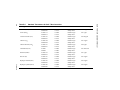
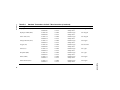
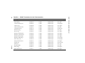
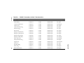
![000 CASORT [9].book](http://vs1.manualzilla.com/store/data/005753997_1-6c1117a0f29b8b2731a0aa33cfc5a43b-150x150.png)