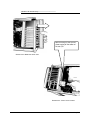
1
PMX-09
PORTABLE 9-SLOT PXIe CHASSIS WITH
INTEGRATED CONTROLLER AND HMI
P/N: 82-0149-000
Released May 22nd, 2014
Rev May 22nd, 2014
VTI Instruments Corp.
2031 Main Street
Irvine, CA 92614-6509
(949) 955-1894
TABLE OF CONTENTS
TABLE OF CONTENTS ................................................................................................................................................ 2
TABLE OF FIGURES ................................................................................................................................................... 4
Certification .......................................................................................................................................................... 5
Warranty ............................................................................................................................................................... 5
Limitation of Warranty ......................................................................................................................................... 5
Trademarks ........................................................................................................................................................... 5
Restricted Rights Legend ...................................................................................................................................... 5
GENERAL SAFETY INSTRUCTIONS ............................................................................................................................. 6
Terms and Symbols .............................................................................................................................................. 6
Warnings ............................................................................................................................................................... 6
Improper Use ........................................................................................................................................................ 7
SUPPORT RESOURCES ............................................................................................................................................... 8
SECTION 1 ..................................................................................................................................................................... 9
INTRODUCTION ......................................................................................................................................................... 9
Overview .............................................................................................................................................................. 9
Unpacking ............................................................................................................................................................. 9
SECTION 2 ................................................................................................................................................................... 11
FEATURES ............................................................................................................................................................... 11
Features............................................................................................................................................................... 11
Slot Configuration .............................................................................................................................................. 12
Speed, Flexibility, and Performance ................................................................................................................... 12
Rugged Design.................................................................................................................................................... 15
Serviceability ...................................................................................................................................................... 15
DETAILED SPECIFICATIONS .................................................................................................................................... 16
General Specifications ........................................................................................................................................ 16
System Synchronization Clocks ......................................................................................................................... 16
Mechanical.......................................................................................................................................................... 17
Electrical ............................................................................................................................................................. 18
Cooling ............................................................................................................................................................... 18
Environmental Specifications ............................................................................................................................. 18
Safety and EMC .................................................................................................................................................. 18
Reliability ........................................................................................................................................................... 19
Serviceability ...................................................................................................................................................... 19
Controller Specifications .................................................................................................................................... 19
I/O CONNECTIVITY ........................................................................................................................................ 19
Display ................................................................................................................................................................ 20
Keyboard ............................................................................................................................................................ 20
Drive Bay ............................................................................................................................................................ 20
SECTION 3 ................................................................................................................................................................... 21
PREPARATION FOR USE........................................................................................................................................... 21
System Power Requirements .............................................................................................................................. 21
Air Flow Requirements ....................................................................................................................................... 21
Turning on the Chassis ....................................................................................................................................... 21
Keyboard & Touchpad operation........................................................................................................................ 21
Power switch and plug ........................................................................................................................................ 23
Power supply ...................................................................................................................................................... 23
Hooking up external monitor: ............................................................................................................................. 24
LCD Display ....................................................................................................................................................... 24
Cooling Fan ........................................................................................................................................................ 25
SECTION 4 ................................................................................................................................................................... 27
HARDWARE INSTALLATION .................................................................................................................................... 27
Remove the Slot Unit.......................................................................................................................................... 27
Open plastic back cover--------------------------- ............................................................................................. 27
2
PMX-09 Features
b. Unscrew the Cooling fan cover------------------------ ................................................................................. 28
c. Unscrew the upper cover of slot unit------------------ ................................................................................. 28
d. Unscrew the side aluminum covers away--------------- .............................................................................. 29
e. Unscrew the inside mounting screws away-------------- ............................................................................. 29
f. Remove the slot unit away------------------------------------ ......................................................................... 29
SECTION 5 ................................................................................................................................................................... 31
MAINTENANCE AND TROUBLESHOOTING ............................................................................................................... 31
Handling of PMX-09: ......................................................................................................................................... 31
Handling of Cable: .............................................................................................................................................. 31
Handling of LCD: ............................................................................................................................................... 31
Handling of Power: ............................................................................................................................................. 31
Handling of Keyboard: ....................................................................................................................................... 31
Cleaning LCD: .................................................................................................................................................... 31
Cleaning Keyboard: ............................................................................................................................................ 32
TROUBLESHOOTING ................................................................................................................................................ 32
Installation problem ............................................................................................................................................ 32
BIOS Beep Code: ............................................................................................................................................... 32
System Fails to power up:................................................................................................................................... 32
No display (LCD): .............................................................................................................................................. 32
External CRT no display: ................................................................................................................................... 33
Keyboard fails:.................................................................................................................................................... 33
TOUCHPAD fails:.............................................................................................................................................. 33
3
PMX-09 Features
TABLE OF FIGURES
Figure 2-1 – PMX-09 Front Overview ....................................................................................................................... 11
Figure 2-2 – PMX-09 Backplane Architecture (4 Link) .............................................................................................. 13
Figure 2-3 – PMX-09 Backplane Architecture (2 Link) .............................................................................................. 14
Figure 2-4 – PMX-09 Backplane Architecture (1 Link) .............................................................................................. 14
Figure 3-1 – Releasing Keyboard ............................................................................................................................... 21
Figure 3-2 – Closing Keyboard ................................................................................................................................... 22
Figure 3-3 – Keyboard Feet ......................................................................................................................................... 22
Figure 3-4 – PMX-09 Touch Pad ............................................................................................................................... 23
Figure 3-5 – PMX-09 Power Switch .......................................................................................................................... 23
Figure 3-6 – Cooling Fans .......................................................................................................................................... 25
Figure 3-7 – Plastic Cover Removal ........................................................................................................................... 27
Figure 3-8 – Removing Cooling Fan Cover ............................................................................................................... 28
Figure 3-9 – Removing Upper Cover ......................................................................................................................... 28
Figure 3-10 – Removing Side Aluminum Covers ...................................................................................................... 29
Figure 3-11 – Removing Mounting Screws ................................................................................................................ 29
Figure 3-12 – Removing Slot Unit ............................................................................................................................. 30
Figure 3-13 – Unplugging Cables ............................................................................................................................... 30
4
PMX-09 Features
CERTIFICATION
VTI Instruments Corp. (VTI) certifies that this product met its published specifications at the time of shipment from
the factory. VTI further certifies that its calibration measurements are traceable to the United States National
Institute of Standards and Technology (formerly National Bureau of Standards), to the extent allowed by that
organization’s calibration facility, and to the calibration facilities of other International Standards Organization
members. Note that the contents of this document are subject to change without notice.
WARRANTY
The product referred to herein is warranted against defects in material and workmanship for a period of one year
from the receipt date of the product at customer’s facility. The sole and exclusive remedy for breach of any warranty
concerning these goods shall be repair or replacement of defective parts, or a refund of the purchase price, to be
determined at the option of VTI. Note that specifications are subject to change without notice.
For warranty service or repair, this product must be returned to a VTI Instruments authorized service center. The
product shall be shipped prepaid to VTI and VTI shall prepay all returns of the product to the buyer. However, the
buyer shall pay all shipping charges, duties, and taxes for products returned to VTI from another country.
VTI warrants that its software and firmware designated by VTI for use with a product will execute its programming
when properly installed on that product. VTI does not however warrant that the operation of the product, or
software, or firmware will be uninterrupted or error free.
LIMITATION OF WARRANTY
The warranty shall not apply to defects resulting from improper or inadequate maintenance by the buyer, buyersupplied products or interfacing, unauthorized modification or misuse, operation outside the environmental
specifications for the product, or improper site preparation or maintenance.
VTI Instruments Corp. shall not be liable for injury to property other than the goods themselves. Other than the
limited warranty stated above, VTI Instruments Corp. makes no other warranties, express or implied, with respect to
the quality of product beyond the description of the goods on the face of the contract. VTI specifically disclaims the
implied warranties of merchantability and fitness for a particular purpose.
TRADEMARKS
LXI® is a registered trademark of the LXI Consortium. Java Runtime Environment™ are trademarks or registered
trademarks of Sun Microsystems, Inc. or its subsidiaries in the United States and other countries. LabVIEW™ and
LabWindows/CVI™ are trademarks of National Instruments Corporation. Visual Basic®, Windows®, and Internet
Explorer® are registered trademarks of the Microsoft Corporation or its subsidiaries. Linux® is a registered
trademark of the Linux Foundation. IVI™ is a trademark of the IVI Foundation. Bonjour™ is a trademark of
Apple, Inc.
RESTRICTED RIGHTS LEGEND
Use, duplication, or disclosure by the Government is subject to restrictions as set forth in subdivision (b)(3)(ii) of the
Rights in Technical Data and Computer Software clause in DFARS 252.227-7013.
VTI Instruments Corp.
2031 Main Street
Irvine, CA 92614-6509 U.S.A.
5
PMX-09 Features
GENERAL SAFETY INSTRUCTIONS
Review the following safety precautions to avoid bodily injury and/or damage to the
These precautions must be observed during all phases of operation or service of this
Failure to comply with these precautions, or with specific warnings elsewhere in this
violates safety standards of design, manufacture, and intended use of the product. Note
product contains no user serviceable parts or spare parts.
product.
product.
manual,
that this
Service should only be performed by qualified personnel. Disconnect all power before servicing.
TERMS AND SYMBOLS
These terms may appear in this manual:
WARNING
Indicates that a procedure or condition may cause bodily injury or death.
CAUTION
Indicates that a procedure or condition could possibly cause damage to
equipment or loss of data.
These symbols may appear on the product or in the manual:
ATTENTION - Important instructions
Indicates hazardous voltage.
Frame or chassis ground
Indicates that the product was manufactured after August 13, 2005. This mark is
placed in accordance with EN 50419, Marking of electrical and electronic
equipment in accordance with Article 11(2) of Directive 2002/96/EC (WEEE).
End-of-life product can be returned to VTI by obtaining an RMA number. Fees
for take-back and recycling will apply if not prohibited by national law.
WARNINGS
Follow these precautions to avoid injury or damage to the product:
6
Use proper Power Cord
To avoid hazard, only use the power cord specified for this product.
Use proper Power Source
To avoid electrical overload, electric shock, or fire hazard, do not
use a power source that applies other than the specified voltage. The
mains outlet that is used to power the equipment must be within 3
PMX-09 Features
meters of the device and shall be easily accessible.
Use proper Fuse
To avoid fire hazard, only use the type and rating fuse specified for
this product.
Power Consumption
Prior to plugging-in PXI modules, it is imperative that the power
consumption of all modules that will be installed in the mainframe
be calculated for all power supply rails. The required information is
available in detailed specifications of this chassis, and respective
I/O card user manuals. Failure to do so may result in damaging the
switch card and the mainframe.
Avoid Electric Shock
To avoid electric shock or fire hazard, do not operate this product
with the covers removed. Do not connect or disconnect any cable,
probes, test leads, etc. while they are connected to a voltage source.
Remove all power and unplug unit before performing any service.
Service should only be performed by qualified personnel.
Ground the Product
This product is grounded through the grounding conductor of the
power cord. To avoid electric shock, the grounding conductor must
be connected to earth ground.
Operating Conditions
To avoid injury, electric shock or fire hazard:
-
Do not operate in wet or damp conditions.
-
Do not operate in an explosive atmosphere.
-
Operate or store only in specified temperature range.
-
Provide proper clearance for product ventilation to prevent
overheating.
-
When selecting the installation location, be certain that there is
enough space around the power plug and the outlet so that they
are readily accessible. Do not insert the power cord into an
outlet where accessibility to the plug cord is poor.
-
All unused slots should be closed with the dummy filler panels
to ensure a proper air circulation. This is critical to avoid
overheating of the cards.
-
DO NOT operate if any damage to this product is suspected.
Product should be inspected or serviced only by qualified
personnel.
IMPROPER USE
The operator of this instrument is advised that if the equipment is used in a manner not specified
in this manual, the protection provided by the equipment may be impaired.
Conformity is checked by inspection.
7
PMX-09 Features
SUPPORT RESOURCES
Support resources for this product are available on the Internet and at VTI Instruments customer
support centers.
VTI Instruments Corp.
World Headquarters
VTI Instruments Corp.
2031 Main Street
Irvine, CA 92614-6509
Phone: (949) 955-1894
Fax: (949) 955-3041
VTI Instruments
Cleveland Instrument Division
5425 Warner Road
Suite 13
Valley View, OH 44125
Phone: (216) 447-8950
Fax: (216) 447-8951
VTI Instruments, Pvt. Ltd.
Bangalore Instrument Division
75, Millers Road
Bangalore – 560 001
Karnataka
India
Phone: +91 80 4040 7900
Fax: +91 80 4170 0200
Technical Support
Phone: (949) 955-1894
Fax: (949) 955-3041
E-mail: [email protected]
Visit http://www.vtiinstruments.com for worldwide support sites and service plan information.
8
PMX-09 Features
SECTION 1
INTRODUCTION
OVERVIEW
The PMX-09 is designed to be a highly integrated and fully portable chassis with 8+1 number of
slots. It features one dedicated slot with EMX-2401 controller pre-installed (optional) and eight
general purpose slots for peripheral PXIe and CompactPCI modules. Complex applications which
require typical PXI characteristics, like timing, synchronization etc, can now take the advantage of
mobility for field use.
The PMX-09 is very easy to maintain because of the easily accessible power supply, fan panel,
and air filter. The optional EMX-2401 PXI Express Embedded Controller makes the chassis to
work standalone, without needing any external computer.
UNPACKING
Upon arrival, the shipping carton should be inspected for damage. If the carton or any of its
contents are damaged please contact VTI Instruments immediately for a replacement. Do not
dispose of the carton or any of its contents; VTI Instruments will not replace the damaged product
if these materials are not returned.
Please check that the following materials are in the carton. If any of these materials are missing
please contact VTI Instruments immediately.
•
•
•
9
PMX-09 3U 9-Slot Chassis, with integrated controller, display & keyboard
User’s Manual
Power Cord
PMX-09 Features
10
PMX-09 Features
SECTION 2
FEATURES
FEATURES
The PMX-09 chassis provides the following features:
•
•
•
•
•
•
•
•
9-slot PXI Express chassis with 1 system controller, 1 timing slot, 1 hybrid slot, and
6 peripheral slots
High bandwidth PCIe 2nd Generation backplane with 2 GB/s slot bandwidth and 8 GB/s
system bandwidth
Sunlight readable display & keyboard
Rugged construction with extended temperature range
Flexible slot-to-slot direct communication for highly-deterministic operations
Partitionable switch architecture with non-transparent bridging for true multi-root support
Industry’s first chassis that is PXI Multicomputing (PXImc) ready
Optional carry case, for ease of transportation and safety
3
4
5
2
1
FIGURE 2-1 - PMX-09 FRONT OVERVIEW
1
2
3
4
5
11
PXI Express Controller Slot
PXI Express Peripheral Slots
Handle
Touch screen display
Detachable keyboard & mouse
PMX-09 Features
SLOT CONFIGURATION
The PMX09 is a 9-slot PXI Express mainframe with 1 system controller slot, 1 PXIe timing slot,
1 PXIe hybrid slot and 6 PXIe peripheral slots.
The PXI Express hybrid slot delivers connectivity to either an x4 PCI Express link or to the 32-bit,
33 MHz PCI bus on the backplane. This allows PXI Express hybrid-compatible, or 32-bit
cPCI/PXI-1 modules (without J2 connector), to be used in this slot.
The PXIe timing slot accepts either a PXI Express module or a PXI Express system timing
controller for advanced timing and synchronization.
The system controller slot has configurable 4x4, 2x8 and 1x8 links, which allows all PXIe
controllers to be supported per spec.
SPEED, FLEXIBILITY, AND PERFORMANCE
Best in Class Bandwidth
The PMX09 uses a 4-lane 2nd generation PCIe backplane to achieve unmatched data rates of up to
2 GB/s per slot and 8 GB/s system. This is especially useful when using high-speed instruments
like digitizers, oscilloscopes, and signal generators.
Advanced PCIe Switch Fabric
The PMX09’s advanced switch fabric uses innovative methods like non-transparent bridging
(NTB) and partitionable switch architecture to allow slot-to-slot direct communication and true
multi-root support.
Slot-to-slot direct communication allows data from any slot to be read directly by another slot
without having to go through the controller and host. This allows extremely high-speed
deterministic data transfers between slots which is very useful for applications that require closed
loop control.
True multi-root support allows any slot to be used as a root-complex meaning data processing or
memory units can be plugged into any slot on the chassis. This combined with slot-to-slot
communication capability allows data to be streamed directly from a plug-in module to a root
complex for storage or processing without burdening the host processor.
12
PMX-09 Features
PXImc Ready
The slot-to-slot direct communication capability combined with true multi-root support allows the
PMX-09 to be the first and only PXImc (PXI MultiComputing) ready mainframe in the industry.
This provides the ability to use multiple processor modules, in any slots on the mainframe, to
share the processing requirements for an application.
This allows PMX-09 to be used in high-speed, high-channel count, applications where large
amounts of streaming data require in-line processing and analysis.
x4
PCIe / PCI
Bridge
x4
PCIe Switch Fabric
x4
x4
1
x4
x4
2
3
x4
4
x4
5
x4
6
x4
7
x4
8
x4
9
Hybrid
FIGURE 2-2 - PMX-09 BACKPLANE ARCHITECTURE (4 LINK)
13
PMX-09 Features
PCIe / PCI
Bridge
x8
PCIe Switch Fabric
x8
1
x4
x4
2
3
x4
4
x4
5
x4
6
x4
7
x4
8
x4
9
Hybrid
FIGURE 2-3 - PMX-09 BACKPLANE ARCHITECTURE (2 LINK)
PCIe / PCI
Bridge
Disabled
PCIe Switch Fabric
x8
1
x4
x4
2
3
x4
4
x4
5
x4
6
x4
7
x4
8
x4
9
Hybrid
FIGURE 2-4 - PMX-09 BACKPLANE ARCHITECTURE (1 LINK)
14
PMX-09 Features
RUGGED DESIGN
The PMX-09’s rugged, compact, and light-weight design makes it ideal for portable applications.
The PMX-09 is available with optional hardened carry case, for ease of transportation and safety.
SERVICEABILITY
The PMX-09 was designed with serviceability in mind. The PMX-09 sports a very modular design
with an easily removable power supply, fan assembly, filter tray and keyboard assembly. The
mentioned components were designed to be easily removed from the chassis to simplify on-site
diagnostics and the replacement of any failed components.
15
PMX-09 Features
DETAILED SPECIFICATIONS
GENERAL SPECIFICATIONS
Total Slots
9 slots
PXI Express System Controller
PXI Express Peripheral
1 slot (slot 1)
6 slots (slots 2, 3, 4, 6, 7, 8)
PXI Express Timing
1 slot (slot 5)
PXI Express Hybrid
1 slot (slot 9)
Module Size
3U
Bandwidth
Slot
2 GB/s
Mainframe
8 GB/s
Standards Compliance
PXI-5 PXI Express Hardware Specifications
PXI-1 hardware specifications Rev 2.2
PICMG EXP.0 R1.0 specification
SYSTEM SYNCHRONIZATION
CLOCKS
10 MHz System Reference Clock:
PXI_CLK10
Max slot-to-slot skew
1 ns
Accuracy
±100 ppm Max
Max Jitter
5 ps RMS Phase Jitter
Duty Factor
45 to 55%
100MHz System Reference Clock:
PXI_CLK100
Max slot-to-slot skew
200 ps
Accuracy
±100 ppm Max
Max Jitter
< 1 ps RMS Phase Jitter (10 Hz to 12 kHz)
< 1 ps RMS Phase Jitter (12 kHz to 20 MHz)
Duty Factor
16
45 to 55%
PMX-09 Features
MECHANICAL
Size
10.8’’ L x 10.52’’ D x 7.43’’ H
Weight
30 - 35 lbs.
17
PMX-09 Features
ELECTRICAL
AC Input
Input Voltage Range
Input Frequency range
Input current
90 to 264 VAC
47 to 63 Hz
Max 8 A @ 115 VAC, 4 A @ 230 VAC
DC Output
PS Connector
Form Factor
Input
Output
AC
ATX 20
PS2 / Mini
AC 100-240V @ 47-63 Hz, full range
2 × 300W
+3.3 V
Max. Load
28 A
Min. Load
0.3 A
COOLING
Fans
Two 130 CFM fans with High / Auto speed modes
Chassis cooling intake
Bottom of front bezel, bottom panel of chassis
Chassis cooling exhaust
Rear of chassis
Slot airflow direction
Bottom of module to top of module
ENVIRONMENTAL
SPECIFICATIONS
Temperature
Humidity
Shock
Vibration (5-500 Hz)
Operating
Non-Operating
0 ºC ~ 50 ºC (32 ~ 113 ºF)
-20 ~ 60 ºC (-4 ~ 140 ºF)
20 ~ 90 % @ 40 ºC, non-condensing
10 ~ 95 % @ 40 ºC,non-condensing
10 G
30 G
1.0 Grms
2.0 Grms
SAFETY AND EMC
Safety Compliance
EN 61010-1, IEC 61010-1
UL 61010-1, CSA 61010-1
2006/95/EC; Low-Voltage Directive (safety)
18
PMX-09 Features
EMC Compliance
EN 61326 (IEC 61326): Class A emissions, basic
immunity
EN 55011 (CISPR 11): Group 1, Class A emissions
AS/NZS CISPR 11: Group 1, Class A emissions
FCC 47 CFR Part 15B: Class A emissions
ICES-001: Class A emissions
RELIABILITY
Backplane
Power supply
MTBF
800,000 hours
100K hours @ Full load
MTTR
5 minutes
SERVICEABILITY
CONTROLLER SPECIFICATIONS
CPU
Chipset
Memory
(for detailed specifications of EMX-2401, please refer to its user manual)
Intel® Core™ i5-520E, 2.4 GHz, 4 Core
Intel® QM57 Express Chipset
RAM - Dual-channel DDR3 SDRAM, 800/1066 MHz (expandable up to 8GB)
Cache - 3 MB
Hard Drive / Storage
Video
Operating Systems
160 GB, 2.5’’ SATA II SSD,
Integrated Intel graphics
Microsoft Windows® 7 (64-bit) is available pre-installed
Other operating systems can be installed by the user
I/O CONNECTIVITY
ETHERNET
Two RJ-45 connectors
Intel® 82574L Gigabit Ethernet controller
USB
GPIB
4 x USB 2.0 on the faceplate
Micro-D 25-pin connector on the faceplate
(ACL-IEEE488-MD1-A cable required)
Onboard IEEE488 GPIB controller
TRIGGER I/O
EXPRESSCARD/34
SMB connector, programmable direction
ExpressCard 34mm expansion slot
BACKPLANE
PCIE LINK CONFIGURATION
BANDWIDTH
2x8 or 4x4, automatically selected based on chassis configuration
2 GB/s max to/from the processor
4 GB/s max between PCIe backplane links in 2-link mode
PXI TRIGGER BUS ROUTING
19
Selectable to/from all 8 PXI_TRIG lines
PMX-09 Features
DISPLAY
Touch panel
Display
Resolution
Illumination
Protection
Resistive touch panel
15.1” high brightness TFT
Up to 1024 x 768
250nits
Yes (tempered glass if w/o touch screen)
Conversion BD
CB-7301
Keys
108 keys
KEYBOARD
Touch Pad
Yes
DRIVE BAY
DVD-ROM
20
Slim type
PMX-09 Features
SECTION 3
PREPARATION FOR USE
SYSTEM POWER REQUIREMENTS
The PMX-09 operates from 90 V to 264 V AC at 43 Hz to 63 Hz. A power source providing at
least 920 VA is required in order for the chassis to function correctly.
AIR FLOW REQUIREMENTS
The PMX-09 is designed to intake air from the sides and front of the unit. The fans pull air into the
unit from the sides and front ventilation ports of the unit and push it out of the rear.
Placing objects against the ventilation ports on either side of the chassis or against the rear of the
unit will obstruct airflow and cause the chassis to overheat. Prolonged obstruction of ventilation
can cause permanent damage to the chassis. Therefore, consideration should be given when
placing objects around the chassis so that the airflow is not obstructed.
If the internal temperature of the chassis exceeds 90 °C for more than 15 minutes the chassis will
immediately shut down. Similarly, if the internal temperature reaches 100 °C the chassis will also
immediately shut down.
TURNING ON THE CHASSIS
The chassis will not power on until a controller has been installed. A VTI controller (such as the
EMX-2401) or similar controller must first be installed.
KEYBOARD & TOUCHPAD OPERATION
How to release
There are two release buttons located on the top-left and top-right
of the keyboard. When depressed, the keyboard is disengaged
from the portable and will release the keyboard structure. There
are also two mounting leg located at the bottom of the keyboard
that are inserted into the portable for fitting and stability, in
which case you can start lifting the keyboard upward. The
keyboard now can then be removed for usage.
FIGURE 3-1 – RELEASING KEYBOARD
PMX-09 Bench-Top Use
21
How to close keyboard
Closing the keyboard back onto the portable follows the same procedure as opening, in a reverse
manner. It is noted that the keyboard cable should be put back into its proper lodging location.
Make sure the two locking mechanism are properly secure after it is put back.
FIGURE 3-2 - CLOSING KEYBOARD
What to look for
The keyboard cable is located on the top portion of the keyboard; it is a coil cable with a RJ45
connector at the end. The jack should now be removed and attach to the portable (at the lower
right hand corner) to be operational.
Keyboard Usage
Keyboard is the main medium for inputting data into the system. The keyboard of the PMX09series portables contains both a keyboard and a touch pad. Keyboard is a 108-keys Windows
ready keyboard with power function and shortcut keys.
Keyboard Position
You may want to adjust the keyboard angle by tilting the feet of the keyboard located at the
bottom
FIGURE 3-3 – KEYBOARD FEET
22
PMX-09 Bench-Top Use
TOUCHPAD operation
TOUCHPAD surface can be use to move the cursor in the
GUI environment by placing and moving your finger. The
two buttons located below the touch pad act as same as the
mouse left/right button. Or you may wish to tap on the
touch pad to indicate a left click.
FIGURE 3-4 – PMX09 TOUCH PAD
POWER SWITCH AND PLUG
The power receptacle is located on the right side of the machine near the bottom. The three-prong
power plug is supplied. Depending on your Power supply type, you may find a main power
switch located next to the power receptacle and the position of the switch is of the following:
O=Off, I=On. This is the main power, to power up the system, user still require to power on the
machine at the front of the portable, labeled Power. If your power supply does not have a main
switch, user will control power on/off using the power switch located in the front.
FIGURE 3-5 – PMX09 POWER SWITCH
POWER SUPPLY
There are three kind of power supply.
As long as one of these has problem, the other will take turn and alarm beep will remind you to
change the defect one.
PMX-09 Bench-Top Use
23
HOOKING UP EXTERNAL MONITOR:
The external CRT monitor / Projector can be hooked up via the side panel VGA (15pin) port while
the system is off. The CRT/Projector will provide the cable to be inserted into this port. When
connected, the display should come on if the machine is powered on. The signal is standard with
the internal viewing resolution and the default setting is simultaneous display both on portable’s
LCD and CRT. To change the output mode (Simultaneous/LCD only/CRT only), please refer to
your VGA setting.
LCD DISPLAY
The LCD display has a fix mechanism. You may till up the pair of feet, which are at the bottom of
the case to lift the LCD display toward the main chassis will release the display. You may adjust
your portable to a comfortable viewing position by tilting the LCD. To relock the LCD display,
simply push the display back into its original position.
24
PMX-09 Bench-Top Use
COOLING FAN
The cooling fan on the right side is easy for removable. There are two cooling fans with 41 CFM
for each socking out the heat to make the whole slot unit be in the working temperature, and they
are easily exchanged to a new or better one.
FIGURE 3-6 – COOLING FANS
PMX-09 Bench-Top Use
25
26
PMX-09 Bench-Top Use
SECTION 4
HARDWARE INSTALLATION
Before you attempt to open the PMX-09and do any hardware installation, make sure you have the proper
knowledge of installation and compatibility feature of any upgrade. And understand the concept of electrostatic
damage that can occur during handling of sensitive electronic equipment, proper precaution should be taken
before proceeding.
REMOVE THE SLOT UNIT
a. Open plastic back cover---------------------------
Unscrew
Unscrew
Unscrew
Unscrew
FIGURE 3-7 – PLASTIC COVER REMOVAL
※ The screws are well-designed that won’t be departed from the back cover.
PMX-09 Bench-Top Use
27
b. Unscrew the Cooling fan cover------------------------
Unscrew
Unscrew
Please unplug before
moving the back cover.
FIGURE 3-8 – REMOVING COOLING FAN COVER
c. Unscrew the upper cover of slot unit------------------
PXI Slot
Unit
Rear
I/O
FIGURE 3-9 – REMOVING UPPER COVER
28
PMX-09 Bench-Top Use
d. Unscrew the side aluminum covers away---------------
FIGURE 3-10 – REMOVING SIDE ALUMINUM COVERS
e. Unscrew the inside mounting screws away--------------
Unscrew
Unscrew
FIGURE 3-11 – REMOVING MOUNTING SCREWS
PMX-09 Bench-Top Use
29
f. Remove the slot unit away------------------------------------
Before moving out the slot unit,
please unplug all the cables on
the rear I/O.
FIGURE 3-12 – REMOVING SLOT UNIT
FIGURE 3-13 – UNPLUGGING CABLES
30
PMX-09 Bench-Top Use
SECTION 5
MAINTENANCE AND TROUBLESHOOTING
HANDLING OF PMX-09:
You should always make sure the keyboard assembly is properly closed onto the PMX-09before
transporting it. This will ensure you do not lose the keyboard as well as protecting the LCD
screen. You may transport the portable in its carrying case, or you can carry the PMX-09on its
handle located on top of the machine. The handle is located securely to the strongest part of the
machine, and distributes the load of the PMX-09 evenly as to allow easy carriage and proper
balance.
HANDLING OF CABLE:
All cable should be treated with care. Do not over extend any cable and this could result in
breakage internally in the cable. It is essential that cable with its plug be handled in the proper
manner without force.
HANDLING OF LCD:
Do not use any abrasive material to scratch the LCD screen, as they can leave marks on the
surface. Do not apply any pressure to the surface of the LCD screen either with objects or hands;
this will ensure that the screen do not suffer from internal damage or cracks.
HANDLING OF POWER:
Always make sure the power cord is in top condition before using them with the GCP 382. Make
sure your power source is reliable and of proper standard. The PMX-09 power supply is capable
of handling 100-240V and 50-60Hz. Do not use the PMX-09 on an already overloaded circuit.
HANDLING OF KEYBOARD:
The keyboard is essential in that it helps protect the LCD during transportation. You should
always watch for spill liquid or small objects from entering the keyboard. And the touch pad
surface should be kept dry and clean for proper usage.
CLEANING LCD:
1.
Do not use cleaner that contain alcohol.
2.
Do not use cloth that could be abrasive to the surface of the LCD
3.
Always gently wipe the LCD surface when cleaning.
PMX-09 Bench-Top Use
31
CLEANING KEYBOARD:
1.
Do not spill any liquid on to the keyboard.
2.
Do not drop particle into the spacing between keys.
3.
Using a compress air cleaner, you can remove the dust built-up within.
TROUBLESHOOTING
INSTALLATION PROBLEM
1.
Normally problem with fail start up are due to installation problem.
2.
Double check with all the peripheral cards or items you have added to the PMX-09.
3.
Are all the items seated properly?
4.
Are all the cable connected back to its original or correct position?
5.
Are the items you have added compatible?
6.
Before you check for these turn the computer off and unplug the power cord.
7.
Check for 1 thru 5 and then re-power up the computer.
8.
Remove all items that were added and re-try system power up.
9.
If the system starts now, try inserting 1 new item in at a time and try powering up.
10.
Repeat this step until you get the desire result
BIOS BEEP CODE:
The BIOS beep code indicates error in system initialization. The BIOS of the system board will
associate with video and memory error. Please check your video card is properly seated and your
memory is installed properly.
SYSTEM FAILS TO POWER UP:
1.
Check you power connection first.
2.
Check the main power switch is in the ON position.
3.
Press the power button located in front of the machine
NO DISPLAY (LCD):
32
1.
Check all the proper power up procedure has been taken.
2.
Hook up an external CRT to the VGA port check if video is present.
PMX-09 Index
3.
If video is present on external CRT, check the internal LCD cable connection.
4.
Or check your VGA setting using a CRT to make sure LCD video is enabled.
5.
If there is no video on external, check your system makes sure everything is seated
properly
6.
If everything is seated properly and still no video, call us for further assistance.
EXTERNAL CRT NO DISPLAY:
1.
Check to see if you have internal LCD video.
2.
Check your CRT is functioning properly.
3.
Check your VGA setting to make sure external video is enabled.
KEYBOARD FAILS:
1.
Make sure the keyboard plug is inserted completely into the portable.
2.
Make sure you do not have another keyboard connected to the side I/O PS/2 port.
TOUCHPAD FAILS:
1.
Make sure the keyboard plug is inserted completely into the portable.
2.
If you have an external PS/2 mouse hook up on the side I/O PS/2 port, the touch pad will
not function simultaneously.
3.
If your operating system requires and does not load the mouse driver automatically, make
sure you have the proper mouse driver loaded.
PMX-09 Bench-Top Use
33