1
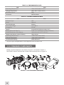
Bit 5x
Bit 5x-10x
Digital Night Vision Monoculars
Operation and
Maintenance Manual
Important Export Restrictions! Commodities, products, technologies and services of this manual are controlled by the U.S.
Department of State Office of Defense Trade Controls, in accordance with International Traffic in Arms (ITAR), Title 22, Code of
Federal Regulations Part 120-130 and/or by the Export Administration Regulations (EAR) of U.S. Department of Commerce. At any
time when a license or a written approval of the U.S. Government
is applicable to it, it is illegal and strictly forbidden to export, intend to export, transfer in any other manner whatsoever, sell any
hardware or technical data, provide any associated service to any
non-U.S. resident, beyond or within the United States territory,
until the valid license or written approval has been issued by the
Departments of the U.S. Government having jurisdiction. Additionally U.S. law prohibits the sale, transfer, or export of items to
certain restricted parties, destinations, and embargoed countries,
as identified on lists maintained by the U.S. Department of State,
the U.S. Department of Commerce, and the U.S. Department of
Treasury. It is the responsibility of the Customer to be aware of
these lists. The sale, transfer, transportation, or shipment outside of the U.S. of any product prohibited or restricted for export
without complying with U.S. export control laws and regulations,
including proper export licensing, documentation or authorization, is unlawful and may result in civil and/or criminal penalties
and/or constitute a federal crime. Diversion contrary to U.S. law
is strictly prohibited.
SAFETY SUMMARY
Before operating this product, you must carefully study this Operation and Maintenance Manual.
The Armasight Bit Digital Night Vision Monocular is a precision electro-optical instrument and requires
careful handling. To avoid physical danger to the user and damage to the equipment, follow all WARNINGS, CAUTIONS and NOTES.
Below are definitions of the alerts that will appear throughout this Manual:
WARNING – Identifies clear danger to the person operating the equipment.
CAUTION – Identifies risk of damage to the equipment.
NOTE – Highlights essential procedures, conditions, and statements, or conveys important instructional data to the user.
The information provided in this manual is for familiarization purposes only. The contents may undergo further
changes with no commitment by Armasight© to notify customers of any updates.
Armasight© assumes no responsibility for any misprints or other errors that this manual may contain.
©2013 by Armasight. All rights reserved.
2
WARNINGS:
This product contains natural rubber latex, which may cause allergic reactions! The FDA
has reported an increase in the number of deaths that are associated with an apparent sensitivity to natural latex proteins. If you are allergic to latex, it is a good idea to learn which products
contain it and strictly avoid exposure to those products.
CAUTION:
• Do not dismantle the equipment.
• Keep the equipment clean. Protect it from moisture, dramatic temperature drops, and electrical shocks.
• DO NOT force the equipment controls past their stopping points.
• DO NOT leave the equipment activated during breaks in operation.
• DO NOT store the equipment with the batteries installed.
• Thoroughly clean and dry each item before placing them into the storage case.
CAUTION:
Although the equipment is highly resistant to damage from light overload, DO NOT point it,
either powered or un-powered, directly at the sun or any other source of high intensity light
that the unprotected human eye cannot tolerate (such as welding arc). To prevent inadvertent
exposure to these light sources, never leave the equipment unsupervised with the objective
lens cap removed.
NOTES:
• DO NOT remove the batteries or disconnect the external power source while the Bit is on.
• Inadvertent sun damage is not considered a defect in material or workmanship, and is therefore not covered in the product warranty.
3
LIST OF CONTENTS
TITLE
Safety Summary
List of Contents
List of Figures
List of Tables
How to Use This Manual
PAGE
2
4
5
6
6
1. INTRODUCTION
1.1 General Information
1.1.1 Type of Manual
1.1.2 Model Number and Equipment Name
1.1.3 Purpose of Equipment
1.1.4 Reporting Equipment Improvement Recommendations
1.2 Warranty Information and Registration
1.2.1 Warranty Information
1.2.2 Limitation of Liability
1.2.3 Product Warranty Registration
1.2.4 Obtaining Warranty Service
1.3 List of Abbreviations
7
7
7
7
7
8
8
8
8
9
9
10
2. DESCRIPTION AND DATA
2.1 System Description
2.2 Bit Specifications
2.3 Standard Components
2.4 Optional Equipment
2.5 Key Features
11
11
12
14
16
17
3. OPERATING INSTRUCTIONS
3.1 Installation and Mounting
3.1.1 Battery Installation
3.1.2 Mounting a Platform Ring to the Bit
3.1.3 Fastening an Advanced Wireless Remote Control 3.1.4 Installing Additional Equipment on the Bit
3.1.5 Connecting Additional Equipment to the Bit
3.1.6 Installing an IR Illuminator on the Bit
3.1.7 Attaching an Afocal Doubler to the Bit
3.1.8 Installing the Bit on a Tripod
3.2 Controls and Display Indications
3.2.1 Bit Controls
3.2.2 IR Illuminator Controls
3.3 Operating Procedures
3.3.1 Operating the Bit
3.3.2 Operating an IR Illuminator
3.3.3 Bit Shut-Down
18
18
18
18
19
19
20
21
22
22
23
23
24
24
24
25
26
4
4. PREVENTIVE MAINTENANCE AND TROUBLESHOOTING
4.1 Preventive Maintenance Checks and Services
4.1.1 Preventive Maintenance Checks and Services (PMCS)
4.2 Operator Troubleshooting
4.3 Maintenance
4.3.1 General
4.3.2 Cleaning Procedures
4.3.3 Battery Removal and Replacement
4.4 Return Instructions
27
27
27
29
29
29
30
30
31
APPENDIX
A List of Spare Parts
B Product Warranty Registration Card
32
32
33
LIST OF FigureS
FIGURE TITLE
2-1
2-2
2-3
2-4
3-1
3-2
3-3
3-4
3-5
3-6
3-7
3-8
3-9
3-10
3-11
3-12
4-1
A-1
Bit Digital Night Vision Monoculars Appearance
Bit Digital Night Vision Monocular. System Description
Bit Standard Components
Optional Equipment
Battery Installation
The Bit Fully Assembled with the Platform Ring
Platform Ring
Advanced Wireless Remote Control
Armasight DT Digital Recorder Installation
Video Cable
IR Illuminator
IR Illuminator. Battery Installation
The Bit with the Afocal Doubler Attached
Bit Controls
IR Illuminator Controls
IR Illuminator Adjustment
Advanced Wireless Remote Control Battery Installation
Bit Spare Parts List
PAGE
11
12
14
16
18
19
19
19
20
20
21
21
22
23
24
25
30
32
5
LIST OF Tables
TABLE
TITLE
2-1
2-2
2-3
2-4
2-5
2-6
2-7
2-8
2-9
3-1
3-2
4-1
4-2
A-1
Bit System Description
System Data
Mechanical Data
Optical Data
Electrical Data
Environmental Data
IR850W Illuminator Data
Bit Standard Components
Optional Equipment
Controls and Indicators
IR Illuminator Controls
Preventive Maintenance Checks and Services
Operator Troubleshooting
Bit Spare Parts List
PAGE
12
12
13
13
13
14
14
15
16
23
24
27
29
32
HOW TO USE THIS MANUAL
USAGE
You must familiarize yourself with the entire manual before operating the equipment. Read the entire
maintenance checklist before performing maintenance. Follow all WARNINGS, CAUTIONS, and NOTES.
MANUAL OVERVIEW
The Manual contains sections on operating and maintaining the Bit Digital Night Vision Monocular.
Throughout this Manual, the Bit Digital Night Vision Monocular will be referred to as the Bit or the
equipment.
A List of Spare Parts is in Appendix A.
The Product Warranty Registration Card is in Appendix B.
6
1
INTRODUCTION
1.1 GENERAL INFORMATION
1.1.1 TYPE OF MANUAL
Operation and Maintenance (including a List of Spare Parts).
1.1.2 Model Number and Equipment Name
Bit 5x Digital Night Vision Monocular.
Bit 5x-10x Digital Night Vision Monocular.
1.1.3 PURPOSE of Equipment
The Bit is a professional grade, Digital Night Vision Monocular with optical 5x or 10x magnification, making
it the most powerful monocular in its class. Sensitive to both near-infrared and visible light, the high performance CCD imaging system of the Bit provides round-the-clock observation. The Bit is effective regardless
of light conditions - in daylight, in natural lighting, and at nighttime. The Bit is an ideal product for both
professional and amateur use, such as hunting, security, law enforcement, general nighttime observation,
and recording.
The Bit is available in two versions, with magnifications of 5x and 10x. The magnification of the Bit 5x can be
changed to 10x by using an optional afocal lens attachment.
The Bit is powered by two CR 123A (2×3V) batteries. An external battery supply or 6 VDC/1A power source
can also be used to power the Bit.
The Bit can be controlled by a wireless remote control.
A detachable, long-range IR illuminator provides additional lighting and enables the use of the Bit in extremely low light conditions or total darkness.
The Bit is equipped with a standard NTSC/PAL video input/output function that makes it possible to connect to an external video monitor, or to record images for field documentation or training purposes. It also
allows the transmission of data from a remote display to that of the Bit.
The Bit can be used in conjunction with other Armasight equipment, such as the Recorder DT Digital Video
Recorder and External Battery Power Supply. The additional equipment can be mounted onto the Bit’s
Picatinny/Weaver rail or detachable platform ring.
Extremely reliable and versatile, the Bit is a valuable, multifunctional addition to any security or hunting.
7
1.1.4 Reporting Equipment Improvement Recommendations
User recommendations for improvements to the device are encouraged.
Mail your comments to:
Armasight Inc.
815 Dubuque Avenue
South San Francisco, CA 94080
USA
Or, send an email to [email protected].
1.2warranty INFORMATION and Registration
1.2.1 WARRANTY INFORMATION
This product is guaranteed to be free from manufacturing defects in material and workmanship under
normal use for a period of two (2) years from the date of purchase. This warranty does not cover the
battery or damage caused by leaking batteries, nor does it protect against damage due to loss, misuse
or mishandling.
In the event a defect that is covered by the warranty occurs during the 2 year period stated above, Armasight, at its option, will either repair or replace the product, and such action on the part of Armasight
shall be the full extent of Armasight’s liability, and the Customer’s sole and exclusive remedy. This warranty does not cover a product (a) used in other than its normal and customary manner; (b) subjected
to misuse; (c) subjected to alterations, modifications or repairs by the Customer or by any party other
than Armasight without prior written consent of Armasight; (d) special order or “close-out” merchandise or merchandise sold “as-is” by either Armasight or the Armasight dealer; or (e) merchandise that
has been discontinued by the manufacturer and either parts or replacement units are not available due
to reasons beyond the control of Armasight. Armasight shall not be responsible for any defects or damage that in, Armasight’s opinion, is a result from the mishandling, abuse, misuse, improper storage or
improper operation, including use in conjunction with equipment which is electrically or mechanically
incompatible with or of inferior quality to the product, as well as failure to maintain the environmental
conditions specified by the manufacturer.
This warranty is extended only to the original purchaser. Any breach of this warranty shall be waived
unless the customer notifies Armasight at the address noted below within the applicable warranty
period.
The customer understands and agrees that except for the foregoing warranty, no other warranties
written or oral, statutory, expressed or implied, including any implied warranty of merchantability or
fitness for a particular purpose, shall apply to the product. All such implied warranties are hereby and
expressly disclaimed.
1.2.2 Limitation of Liability
Armasight will not be liable for any claims, actions, suits, proceedings, costs, expenses, damages or
liabilities arising out of the use of this product. Operation and use of the product are the sole responsibility of the Customer. Armasight’s sole undertaking is limited to providing the products and services
outlined herein in accordance with the terms and conditions of this Agreement. The provision of products sold and services performed by Armasight to the Customer shall not be interpreted, construed,
or regarded, either expressly or implied, as being for the benefit of or creating any obligation toward
any third party or legal entity outside Armasight and the Customer. Armasight’s obligations under this
Agreement extend solely to the Customer.
Armasight’s liability hereunder for damages, regardless of the form or action, shall not exceed the fees
or other charges paid to Armasight by the customer or customer’s dealer. Armasight shall not, in any
event, be liable for special, indirect, incidental, or consequential damages, including, but not limited to,
lost income, lost revenue, or lost profit, whether such damages were foreseeable or not at the time of
purchase, and whether or not such damages arise out of a breach of warranty, a breach of agreement,
negligence, strict liability or any other theory of liability.
8
1.2.3 Product Warranty Registration
In order to validate the warranty on your product, Armasight must receive a completed Product Warranty Registration Card for each unit, or the Customer can complete a warranty registration on our
website at www.armasight.com. Please complete the included form (Appendix B) and immediately
mail it to our Service Center:
Armasight Inc.
815 Dubuque Avenue
South San Francisco, CA 94080
USA
1.2.4 Obtaining Warranty Service
To obtain warranty service on your unit, the End-user must notify the Armasight’s service department
in order to receive a Return Merchandise Authorization number (RMA#). The customer can do this by
sending an email to [email protected].
When returning any product, please take or send the product, postage paid, with a copy of your sales
receipt, to our service center, Armasight Inc. at the address noted above. All merchandise must be fully
insured with the correct postage; Armasight will not be responsible for improper postage or missing or
damaged merchandise during shipment.
When sending merchandise back, please write the RMA# clearly on the outside of the shipping box.
Please include a letter that indicates your RMA#, Name, Return Address, reason for service return, Contact information (such as a valid telephone number and/or e-mail address), as well as proof of your purchases that will help us to establish the valid start date of the warranty. Product merchandise returns
that do not have an RMA listed may be refused or be subject to a significant delay in processing.
Estimated Warranty service time is 10-20 business days. The End-user/Customer is responsible for postage to Armasight for any warranty service. Armasight will cover return postage/shipping to continental
USA End-users/Customers after warranty repair only if product is covered by the aforementioned warranty. Armasight will return the product after warranty service via domestic ground service and/or domestic mail. The postage and shipping fees for any other requested, required or international shipping
methods will be the responsibility of the End-user/Customer.
9
1.3 List of Abbreviations
µm
AWREC
C
CCW
CW
F
FL
g
H
hr
in
inf.
kg
L
lbs
m
mA
mil
min
mm
MOA
mrad
NO.
NTSC
oz
PAL
PMCS
RMA#
sec
SEQ
SOA
SR
V
W
10
micrometer
Advanced Wireless Remote Control
Celsius (Centigrade)
counterclockwise
clockwise
Fahrenheit
Focal Length
gram
Height
hour
inch
infinity
kilogram
Length
pounds
meter
milliampere
angular mil
minute
millimeter
Minute Of Angle
milliradian
Number
National Television Standards Committee
ounce
Phase Alternating Line
Preventive Maintenance Checks and Services
Return Merchandise Authorization number
second
sequence
Second Of Angle
Service Representative
Volt
Width
2
DESCRIPTION AND DATA
2.1 System DESCRIPTION
The Bit consists of next primary parts: a body, a lens assembly and a eyepiece assembly. The equipment
comes as shown in Figure 2-1. The figure represents the both 5x and 5x-10x versions of the Bit.
The Bit is a highly light-sensitive device. The Bit sensor (CCD array) reacts to near-infrared and visible
light and converts the received light into electric charges. The controlling circuit converts the entire
contents of the two-dimensional array to a sequence of voltages that are processed into a continuous
analog signal. The Bit displays, as a result, a real-time images corresponding to the scene projected
onto the focal plane of the sensor.
Bit 5x
Bit 5x-10x
Figure 2-1. Bit Digital Night Vision MonocularS APPEARANCE
The main optical-electronic components of the Bit include: an objective lens, an eyepiece, a CCD camera, a display, a control card, and a button control panel.
The Bit is equipped with a manually adjustable eyepiece, focusable objective lens, and a digitally controlled display brightness.
Information on the battery status is continuously displayed.
Manufactured for exceptional durability, the Bit has a lightweight and robust aluminum body.
A side Picatinny/Weaver rail allows for the installation of an optional Armasight DT Digital Video Recorder, extended battery supply, or other equipment.
A detachable Platform Ring makes it possible to mount an IR illuminator or other additional equipment
to the top of the device.
A detachable, long-range IR illuminator provides additional lighting and enables the use of the Bit in extremely low light conditions or total darkness.
11
A standard NTSC/PAL video input/output connector enables an external video display (monitor, TV) or
video recorder to be connected to the Bit. An external battery power supply or 6 VDC/1A power source
can also be connected to the Bit.
The Bit is powered by two CR 123A (2×3V) batteries.
The Bit is shown in Figure 2-2. The ITEM NO. column of Table 2-1 indicates the number used to identify
items in Figure 2-2.
5
7
6
8
9
4
3
13
2
12
1
11
10
14
Figure 2-2. Bit Digital Night Vision Monocular. SYSTEM DESCRIPTION
TABLE 2-1. Bit SYSTEM DESCRIPTION
Item
Description
Item
Description
1
Objective Lens Cap
8
Eyepiece Focus Ring
2
Objective Lens
9
Eyecup
3
Objective Focus Ring
10
Turn-pull Switch
4
Body
11
Connector Cap
5
Button Control Panel
12
Connector
6
Battery Cap
13
Side Picatinny/Weaver Rail
7
Eyepiece
14
Tripod Socket
2.2 Bit Specifications
Table 2-2. SYSTEM DATA
Item
CCD Camera
Bit 5x
Pixel CCD Array Format
752×582
CCD Array Spectral Response
Resolution
Display Type
Pixel Display Format
12
Bit 5x-10x
High-rate High Resolution Near-IR Hypersensitive CCD Camera
0.4 to 1.1 µm
30 SOA
15 SOA
AMOLED SVGA 060
800×600
table 2-2. continued
Bit 5x
Item
Display Brightness
Bit 5x-10x
Discretely Adjustable to 8 Levels
Turn-on Time, max
3 sec
Analog Input Format
PAL/ NTSC
Analog Output Format
PAL
PAL Output Resolution
768×574 pixels
Table 2-3. Mechanical Data
Item
Overall Dimensions
Weight (w/o Batteries)
Bit 5x
Bit 5x-10x
240×69×65mm (9.4”×2.7”×2.6“)
335×70×74mm (13.2”×2.8”×2.9“)
0.74 kg (1.6 lbs)
1.07 kg (2.4 lbs)
Table 2-4. Optical Data
Item
Magnification
Field of View
Bit 5x
Bit 5x-10x
5x
(10x with optional
Afocal Doubler)
5x or 10x
(10x with included
Afocal Doubler)
- ang. X degrees
5.7°
3.2° (with Afocal Doubler)
- ang. Y degrees
4.2°
2.3° (with Afocal Doubler)
50mm
90mm (with Afocal Doubler)
Objective Focal Length
Objective F-number
1:1.2
1:1.4 (with Afocal Doubler)
Eyepiece Focal Length
Entrance Pupil Diameter
25 mm
42mm
65mm
Exit Pupil Diameter
10 mm
Eye Relief
45 mm
Focus Method
Manual
Focusing Range
10m to infinity
10m to infinity
Diopter Adjustment
Manual
Diopter Adjustment Range
±5 diopter
Table 2-5. Electrical Data
ITEM
DATA
Battery
Two CR123A Lithium 3V or CR123 type
rechargeable batteries with voltage 3.2V
Current Consumption, maximum
500 mA
Battery Life at 20 °C (68 °F)
up to 3 hr
External Battery Power Supply 1
Four AA Lithium batteries (1.5V) or AA rechargeable batteries (1.2V) / Operational Time up to
3.5 hr
External Battery Power Supply 2
External Power Supply
Two 18650 rechargeable batteries (3.7V) or four
CR123 type rechargeable batteries with voltage
3.7V max. / Operational Time up to 7 hr
6 VDC / 1 А
13
Table 2-6. Environmental Data
ITEM
DATA
Operating Temperature
-40 to +50°C (-40 to +122°F)
Storage Temperature
-50 to +70°C (-58 to +158°F)
Recoil Resistance
700g
Immersion
10m for 30 min
Table 2-7. IR850W illuminator DATA
ITEM
data
IR Emitter Type
Power
Peak Wavelength
Illumination Range
Divergence
Battery
Battery Life at 20 °C (68 °F)
Overall Dimensions (with Mount)
Weight (with Mount, without Battery)
Operating Temperature
Storage Temperature
Environmental Rating
LED
500 mW
850 nm
up to 500 m
2 to 30°
Single CR123А Lithium battery (3V) *
From 1.5 hr (Full Power) to 10 hr (1/4 Power)
120×42×38 mm (4.7”×1.6”×1.5”)
102 g (3.6 oz)
-30 to +50°С (-22 to 122°F)
-50 to +70°С (-58 to 158°F)
Water Resistant
* Any CR123 type rechargeable batteries with voltage from 3.0V to 3.7V can be used
2.3 STANDARD COMPONENTS
The Bit standard components are shown in Figure 2-3 and listed in Table 2-8.
The ITEM NO. column indicates the number used to identify items in Figure 2-3.
1
3
6
5
10
7
8
9
2
4
11
Figure 2-3. Bit STANDARD COMPONENT
14
12
13
TABLE 2-8. Bit STANDARD COMPONENTS
ITEM no.
DESCRIPTION
QUANTITY
1
Armasight Bit Digital Night Vision Monocular
A Digital Night Vision device.
1
2
Objective Lens Cap
Protects the objective lens from dirt and mechanical damage, and provides protection
from light overload. Comes attached to the objective lens.
1
3
Eye-cup
A rubber cup used to protect the eyepiece as well as provide comfort for the operator.
Comes attached to the eyepiece.
1
4
Battery Cassette
Intended for the installation of two CR123 batteries in the battery compartment. The Bit
comes with two battery cassettes (includes one installed in the battery compartment
and one spare cassette).
2
5
CR123A Lithium Battery
Batteries are used to power the Bit.
2
6
Advanced Wireless Remote Control (AWREC)
Allows the user to operate the Bit in remote activation mode. Ensures quick and silent
activation/deactivation of the equipment. Comes with CR2032 (3V) battery installed.
1
7
Picatinny Adapter for Advanced Wireless Remote Control
Allows the advanced wireless remote control to be installed on a weapon’s Picatinny/
Weaver rail.
1
8
IR850W Detachable Wide Angle Adjustable X-Long Range Infrared Illuminator
A detachable LED long-range infrared illuminator with a wide, adjustable beam angle.
Compatible with night vision devices that rely on CCD or image intensifier technology.
Should be used when there is little to no ambient light. Comes fully assembled with a
dedicated mount in order to be installed on a Picatinny/Weaver rail.
1
9
Platform Ring
A dedicated mount with a Picatinny/Weaver rail, used to install on the top of the Bit and
additional equipment, such as the Armasight MCS Miniature Collimating Sight.
1
10
Video Cable
A cable used to connect the analog video input/output of the Bit to external display
devices (a monitor, TV) or power sources. The cable plug A is used for video, the plug B
is used for external power surse connection.
1
11
Afocal Doubler (Bit 5X-10X only)
2x magnifying lens intended for long-range operation. Comes complete with an thread
adapter and three M2×3 screws that are required to mount the lens to the Bit.
1
12
Operation and Maintenance Manual
Provides safety information, equipment description, mounting procedures, operating
instructions, and preventive maintenance checks and services (including a List of Spare
Parts).
1
13
Carrying Case
A textile bag used for the transportation and storage of the Bit and its accessories.
1
15
2.4 Optional Equipment
Optional items are shown in Figure 2-4 and listed in Table 2-9.
The ITEM NO. column indicates the number used to identify items in Figure 2-4.
The PART NO. column indicates the primary number used by the manufacturer, to identify an item.
1
2
3
4
5
Figure 2-4. OPTIONAL EQUIPMENT
TABLE 2-9. OPTIONAL EQUIPMENT
ITEM NO.
DESCRIPTION
Part no.
1
Digital Video Recorder DT
A compact digital video recorder used for video recording, storage and
playback. Can also serve as an external power source. Equipped with a remote
control.
ATAM000004
2
External Battery Power Supply 1
The power surce for extended operational time. Takes four AA batteries (1.5V)
or AA rechargeable batteries (1.2V).
ATAM000007
3
External Battery Power Supply 2
The power source for extended operational time. Takes four CR123A Lithium
batteries (1.5V) or CR123 type rechargeable batteries (3.2V or 3.7V) or two
18650 type rechargeable batteries (3.7V).
ATAM000008
4
Afocal Doubler for Bit 5X
An accessory 2x magnifying lens intended for long-range operation. Comes
complete with an thread adapter and three M2×3 screws that are required to
mount the lens to the Bit 5X.
Hard Shipping/Storage Case
A protective case used for the shipping/storage of the Bit and its accessories.
ANAF18X039
5
16
ANHC000004
2.5 Key Features
–––
–––
––
––
–––
–––
–––
–
Available in two versions — with magnification of 5x and 10x
High-performance CCD camera
Bright-light tolerance
An effective regardless of light conditions - in daylight, in natural lighting, and at nighttime.
Lightweight and robust design
Easy to operate
Manually adjustable eyepiece and objective lens
Real-time display
Digitally controlled display brightness
Indication of the battery status information on the display
Wireless remote control
Analog video input (NTSC/PAL) and output (PAL)
Powered by two standard CR123A batteries
Power input capability
Tripod mountable
Digital video recorder (optional)
Serviceability under severe conditions
Filled with dry nitrogen to prevent internal fogging
Waterproof
Limited two-year warranty
17
3
OPERATING INSTRUCTIONS
3.1 Installation and Mounting
3.1.1 Battery Installation
CAUTION:
Before installing a battery, verify that the equipment is off.
Install two CR123A batteries as follows (refer to Figure 3-1):
1. Unscrew the battery cap (A).
2. Remove the battery cassette (B).
3. Insert the batteries (C) into cassette. Align the polarity symbols on the batteries with the polarity
symbols on the cassette.
4. Insert the cassette with installed batteries to place.
5. Replace the battery cap.
a
b
c
Figure 3-1. BATTERY INSTALLATION
3.1.2 Mounting a Platform Ring to the Bit
Figure 3-2 shows the Bit with the Platform Ring adapter (A) installed.
To mount the Platform Ring on the Bit, do the following (refer to Figure 3-3):
1. Using a 1.5 hex key, unscrew the both clamp screws (C).
2. Place the clamps (B, D) onto the mounting tube (as in Figure 3-2). Screw the clamps together without
tightening the screws (C).
3. Adjust position of the Platform Ring until its rail (A) is level. Apply a small amount of thread lock to
the threads and tighten the screws (C).
18
a
Figure 3-2. THE Bit FULLY ASSEMBLED WITH THE Platform Ring
a
b
c
c
d
Figure 3-3. Platform Ring
3.1.3 Fastening an Advanced Wireless Remote Control
Using Velcro tape (A, Figure 3-4), fasten the remote control (B) in an easily accessible place.
If your equipment has a Picatinny or Weaver rail, you can use the Picatinny adaptor for the Advanced
Wireless Remote (C). Install the adaptor onto the rail (D). Insert the remote control unit into the adapter.
You can also install the Picatinny adaptor onto the Bit side rail or onto the platform ring.
B
B
a
C
D
Figure 3-4. Advanced wireless REMOTE CONTROL
3.1.4 Installing additional equipment on the Bit
Use the side Picatinny/Weaver rail to install any additional equipment, such as the Armasight DT digital
video recorder (see Figure 3-5) or an external battery power supply.
Use the Platform Ring adapter to install any additional equipment, such as the long-range IR illuminator. For adapter mounting procedures, see Part 3.1.2.
19
3.1.5 Connecting additional equipment to the Bit
CAUTION:
Turn off the Bit before you begin connecting/disconnecting any external equipment and before removing the batteries.
Remove the batteries before you connect any external power source.
Remove the connector protective cap.
Connect a cable of Armasight DT digital video recorder or an external battery power supply to the Bit
connector.
Figure 3-5. Armasight DT digital recorder INSTALLATION
Use the plug A of a video cable to connect an external video recorder/monitor/TV to the Bit. Connect
the plug C of a video cable to the Bit connector.
Use the plug B of a video cable to connect an external power source (6 VDC/1A) to the Bit. Connect the
plug C of a video cable to the Bit connector.
A
B
C
Figure 3-6. video cable
NOTE:
The external power supply must have a standard 6mm OD double-pole socket with a positive
center contact.
CAUTION:
After removing the cable, replace the protective cap over the connector.
20
3.1.6 Installing an IR Illuminator on the Bit
Armasight long range IR illuminators are delivered fully assembled with a dedicated mount, to be installed on the side rail of the Bit or on the rail of the Platform Ring mounted to the Bit.
To mount an IR illuminator on a Picatinny/Weaver rail, do the following (refer to Figure 3-7):
1. With the nut (A) loosened, install the mount (B) on the Weaver rail so that the stop (C) slides into one
of the transverse slots of the rail.
2. Tighten the nut (A) using a screwdriver.
D
b
c
A
Figure 3-7. IR ILLUMINATOR
NOTE:
The mount clamp (D) has a spherical hinge that allows to tilt the IR illuminator mounted on the
rail.
Install the CR123A battery as follows (refer to Figure 3-8):
CAUTION:
Ensure that the IR Illuminator is off before installing the battery.
1. Unscrew the battery cap (A).
2. Install the battery (B) into the battery compartment. Align the polarity symbols on the battery with
those on the cap face.
3. Replace the battery cap (A).
a
b
Figure 3-8. IR ILLUMINATOR. BATTERY INSTALLATION
21
3.1.7 Attaching an Afocal doubler to the Bit
Figure 3-9 shows the Bit with an accessory Afocal Doubler lens attached.
Attach the magnifying lens to the Bit as follows:
1. Remove the Bit objective lens cap and place it over the lens housing.
2. Screw the Afocal Doubler (A) into the threading of the Bit objective lens (B) housing. Be careful not
to over-tighten the lens.
a
b
c
Figure 3-9. THE Bit WITH the AFOCAL Doubler ATTACHED
NOTE:
The adapter (C, Figure 3-9) is used for mounting the Afocal Doubler to the Bit. The adapter is
screwed to the threaded portion of the doubler housing and fixed with three M2×3 screws using a 0.9 hex key. The thread adapter switches between M48×1 and M51×1 thread sizes.
NOTE:
With the magnifying lens in place, magnification value changes as well as other parameters,
such as system resolution, field of view, focusing range, etc.
NOTE:
The caution notice DO NOT REMOVE IN DAYLIGHT on the front lens cap of this universal magnifying lens is not applicable when using it on the Bit.
3.1.8 INSTALLINg the Bit on a TRIPOD
The Bit can be installed to a tripod. To mount the tripod with the Bit device, screw the tripod into the
1/4’’ threaded socket located on the Bit’s bottom side.
CAUTION:
The unit may be badly damaged if the tripod collapses or falls over. Remove the unit from the
tripod if it is not within your reach.
22
3.2 Controls and Display Indications
3.2.1 Bit CONTROLS
The Bit controls are shown in Figure 3-10 and are defined in Table 3-1. The ITEM NO. columns of the
tables indicate the number used to identify items in the figures.
4
5
3
2
1
6
Figure 3-10. Bit CONTROLS
CAUTION:
DO NOT force the equipment controls past their stopping points.
TABLE 3-1. CONTROLS AND INDICATORS
item no.
CONTROL/INDICATOR
FUNCTION
1
Eyepiece Focus Ring
Adjusts the eyepiece diopter. The total diopter adjustment range is
covered with 2 turns of the ring.
2
Turn-pull Switch
Activates the Bit when turned to ON.
NOTE:
You must pull the knob before turning in order to activate either
ON or STB.
Activates standby mode when turned to STB (see note above).
Deactivates the Bit when turned to OFF.
3
Display Brightness
Decrease Button
Push the button (3) to decrease the screen brightness.
4
Display Brightness
Increase Button
Push the button (4) to increase the screen brightness.
5
Objective Focus Ring
Focuses the objective lens. Adjusts for sharpest view of the scene.
The total focus range is covered with three quarter turns of the lens.
6
Remote Control Button
Activates/deactivates the Bit in standby mode. To turn the unit on,
press button once, to turn it off – press button again.
—
Battery Status Indicator
(a battery icon on the
the display) *
The light gray bar in the battery icon indicates the current power
level of the internal battery, or remaining battery life.
The totally shaded battery icon indicates the fully charged battery.
The flashing transparent battery icon indicates a low battery.
* The Battery Status Indicator not show a correct power level when the external battery or power supply is
used.
23
3.2.2 IR Illuminator Controls
The controls of the optional IR illuminators are shown in Figure 3-11 and defined in Table 3-2. The ITEM
NO. column indicates the number used to identify items in Figure 3-14.
2
1
Figure 3-11. IR ILLUMINATOR CONTROLS
TABLE 3-2. IR ILLUMINATOR CONTROLS
ITEM NO.
Control
1
Power Switch
2
Lens focus
FUNCTION
Switches the IR illuminator on/off and adjusts for radiated power.
Four ON positions are located between the two OFF positions, and
are each marked with a different-sized spot. The larger the spot, the
greater the radiated power.
Adjusts for IR beam divergence. Adjustment range is covered with
approximately one turn of the lens.
3.3 OPERATIng Procedures
3.3.1 Operating the Bit
CAUTION:
DO NOT force the equipment controls past their stopping points.
CAUTION:
Although the Bit is highly resistant to damage from light overload, DO NOT point it, either powered or un-powered, directly at the sun or any other source of high intensity light that the unprotected human eye cannot tolerate (such as welding arc). To prevent exposure to these types
of sources, never leave the equipment unsupervised with the objective lens cap removed.
Operating procedures are as follows:
1. Remove the Bit from the carrying case.
2. Remove the objective lens cap.
3. Point the equipment at an object.
4. Activate the Bit by turning the turn-pull switch to the ON position. After approximately 3 sec, video
of the scene should appear.
5. Adjust the Bit for your eyesight by turning the eyepiece focus ring CW up to the stop, and then CCW
until the display and symbols are as clear as possible. Bring the object into focus by turning the objective focus ring (CW for long-range focus, CCW for close-range focus).
24
NOTE:
The total diopter adjustment range is covered with 2 turns of the eyepiece focus ring.
The total focus range is covered with 3/4 turn of the objective focus ring.
6. Using the buttons on the control panel, adjust the brightness of the display for your comfort. Momentarily push the brightness adjustment buttons to increase/decrease the display brightness by
one level at a time until you reach your desired brightness level.
7. To operate the Bit with remote control, turn the switch to the STB position (standby mode). To activate the Bit, press the remote control button once. Press the remote control button again to deactivate the Bit.
CAUTION:
DO NOT leave the equipment activated when it is not in use.
3.3.2 Operating an IR Illuminator
Use an IR illuminator when there is little to no ambient light.
CAUTION:
IR illuminator infrared light will be invisible to the naked eye. However, the light can be detected by other night vision devices.
CAUTION:
DO NOT leave the IR illuminator activated if it is not being used.
Operate the IR illuminator as follows:
1. Turn on the IR illuminator by rotating the power switch (A) from OFF position.
2. To change the radiated power level, turn the power switch to one of the spots between the two OFF
positions.
3. To adjust IR beam divergence, turn the lens (B).
4. To adjust the IR spot position in the field of view, loosen the clamp screw (C) and tilt the IR illuminator
as required in the spherical clamp hinge. Tighten the screw using a 2.5 mm hex key.
b
c
A
Figure 3-12. IR ILLUMINATOR adjustment
25
3.3.3 Bit Shut-Down
NOTE:
Shut down the Bit properly to avoid losing unsaved settings and data.
Shut-down the Bit as follows:
1. Turn off the Bit.
2. Replace the cap on the objective lens.
3. Disconnect the cable (if applicable).
4. Place the cap on the connector.
5. Remove the batteries.
CAUTION:
Do not store the Bit with the batteries still installed.
6. Store the Bit and all accessories in the carrying case.
26
4
PREVENTIVE MAINTENANCE AND
TROUBLESHOOTING
4.1 Preventive Maintenance Checks and Services
4.1.1 PREVENTIVE MAINTENANCE CHECKS AND SERVICES (PMCS)
Table 4-1 Preventive Maintenance Checks and Services (PMCS) has been provided so that you can keep
your equipment in good operating condition.
Perform functional tests in the order listed in Table 4-1.
Operating procedures are detailed in Chapter 3.
Explanation of Table Entries:
Seq No. column. Sequence numbers are for reference and appear in the order required to perform
checks and services.
Location/Item to Check/Service column. Indicates the location and the item to be checked or
serviced.
Procedure column. Details the check/ service procedure.
Not Fully Mission Capable If ... column. Indicates what faults will prevent your equipment from
operating successfully.
TABLE 4-1. PREVENTIVE MAINTENANCE CHECKS AND SERVICES
Seq
No.
Location Item to
Check/Service
PROCEDURE
Not Fully Mission
Capable If ...
PRE-OPERATION CHECKS
1
Completeness
Open storage/carrying case and inventory items by
comparing them with the data specified in this manual.
2
Soft Carrying Case
Shake out loose dirt or foreign material. Inspect for tears,
cuts, excess wear or damage.
3
Body
Inspect for cracks or damage. Scratches and gouges are
OK if operation is not affected. Inspect for missing parts.
Clean as required.
Cracked or damaged. Missing parts.
4
Objective
Cap
Inspect for cuts, tears and dirt.
Clean as required.
Cap is torn or cut. Cap is not secured to
the housing of the lens.
5
Eyecup
Inspect for cuts, tears and dirt. Inspect for torn, bent or
improperly fitting eyecup.
Clean as required.
Cup is torn or cut.
Lens
Missing items.
27
table 4-1. continued
Seq
No.
Location Item to
Check/Service
PROCEDURE
Not Fully Mission
Capable If ...
6
Battery Compartment, Cap, and,
Cassette
Inspect for corrosion, moisture, and corroded or defective contacts. Inspect for cap damaged or retainer
breaks. Inspect rubber gasket for damage.
Contacts are damaged or corroded.
Retainer is broken. Cap or rubber gasket is damaged.
7
Lenses
Inspect for cleanliness, scratches, chips or cracks.
Clean as required.
Chipped or cracked. Scratches hinder
visibility.
8
Objective Focus
Ring
Rotate objective focus ring to ensure it is not too tight or
too loose. Range is approximately 3/4 turns.
Ring gets stuck, is too loose, or adversely affects the user’s ability to
properly focus the objective lens.
9
Eyepiece Focus
Ring
Rotate eyepiece focus ring to ensure the ring is not too
tight or too loose. Range is approximately 2 turns.
Ring gets stuck, is too loose, or
adversely affects the user’s ability to
properly adjust the diopter.
10
Turn-pull Switch
Check for operation (without batteries).
Switch is inoperative.
11
Connector
Inspect for corrosion, moisture, and corroded or defective contacts. Inspect for cap damage or retainer breaks.
Contacts are damaged or corroded.
Cap is damaged. Retainer is broken.
12
Remote Control
Unit
Check for damage and missing parts.
Check Velcro tape for wear.
Damaged. Missing parts.
13
Long Range IR
Illuminator
Inspect the body of the IR illuminator and mount for
damage and missing parts.
Check IR Illuminator Power Switch for proper operation.
Check IR Illuminator Battery Cap and O-ring for damage.
Inspect IR Illuminator lens for cleanliness, scratches, chips
or cracks. Clean as required. Check to ensure there is free
rotation through the full range of travel (one turn).
Damaged.
Missing parts.
Switch is inoperative.
O-ring is damaged or missing.
Lens is chipped or cracked. Lens is
sticking or too loose when turned.
14
Platform Ring
Inspect for damage, corrosion, or missing parts. Check
for proper operation. Clean as required.
Damaged. Missing parts.
15
Video Cable
Inspect for damage. Inspect the cable connector for corrosion, moisture, and corroded or defective contacts.
Clean as required.
Damaged.
16
Afocal Doubler
Inspect the Afocal Doubler lens optical surfaces for
cleanliness, scratches, chips or cracks. Clean as required.
Inspect the front cap for cuts, tears and dirt. Inspect
the rear cap for ease of installation and dirt. Clean as
required.
Check ease of attaching and removal of the lens. Clean
as required.
Chipped or cracked. Scratches hinder
vision through the equipment.
The front cap is torn or cut, or is not secured to the housing of the lens. The
rear cap is damaged.
Damaged.
17
Turn-pull Switch
Install the batteries. Remove the objective lens cap.
Point the equipment at an object. Turn the equipment
on. Look for an image on the display. Look for a flashing
battery icon in the eyepiece viewing area.
No image. Battery icon is flashing (indicates a low battery).
18
Control Board
Ensure the Bit is responsive to control buttons.
Unresponsive buttons.
19
Remote Control
Turn the equipment to standby. Point the equipment at
an object. Press the remote control button. Look for an
image on the display. Press the button again. Turn off the
equipment.
No image.
20
Video Cable
Connect an external monitor to the Bit. Point the equipment on an object. Turn the equipment on. Look for an
image on the monitor. Turn off the Bit. Disconnect the
monitor.
No image.
21
Long Range IR
Illuminator
Insert the battery. Mount the IR illuminator onto the Bit.
Turn the IR illuminator on. Direct the radiated beam at a
wall from a distance of about 5 m. Look through the Bit.
A square of light should appear on the wall.
No light appears on the wall.
OPERATIONAL CHECKS
POST-CHECK PROCEDURES
Turn off the equipment.
Replace the objective lens cap.
Remove the batteries.
Return the equipment and all accessories to the carrying case.
28
4.2 OPERATOR TROUBLESHOOTING
The purpose of troubleshooting is to identify the most frequent equipment malfunctions, probable
causes, and corrective actions required.
Table 4-2 lists the common malfunctions that may be found during the operation or maintenance of
the Bit. Perform the tests/inspections and corrective actions in the order listed.
This table does not list all of the malfunctions that may occur with your device, or all of the tests
and corrective actions that may be necessary. If you experience an equipment malfunction that is
not listed, or is not fixed by the corrective actions listed in the table, please contact Armasight’s Customer Service center.
TABLE 4-2. Operator Troubleshooting
Malfunction
The Bit fails to activate.
PROBABLE CAUSE/ TEST/INSPECTION
Corrective Action
Batteries are missing or improperly installed.
Insert batteries or install correctly.
Batteries are dead.
Replace the batteries.
Batteries, surfaces or contacts are dirty
or corroded.
Clean the contact surfaces with a pencil eraser
and/or alcohol and cotton swabs.
Remote control unit is damaged.
Please contact Customer Support.
Remote control battery is dead.
Replace the battery as per Part 4.3.4.
The equipment is damaged.
Please contact Customer Support.
The Bit is not responsive to
control buttons.
The equipment is damaged.
Please contact Customer Support.
Remote control does not
work.
Battery is missing or improperly installed.
Insert battery or install correctly.
Battery is dead.
Replace the battery.
Battery surfaces or contacts are dirty or
corroded.
Clean the contact surfaces with a pencil eraser
and/or alcohol and cotton swabs.
Poor image quality.
Remote control unit is damaged.
Please contact Customer Support.
Check objective lens and eyepiece focus.
Refocus.
Check for fogging or dirt on objective
lens and eyepiece.
Clean the lenses as detailed in Part 4.3.2.
The equipment is damaged.
Please contact Customer Support.
No image
Video cable is damaged.
Replace the video cable with a new one. Please
contact Customer Support.
The equipment is damaged.
Please contact Customer Support.
Hindered rotation of the
battery cap.
Dirty cap thread.
Clean the thread.
Damaged cap thread.
Replace the cap with a new one. Please contact
Customer Support.
Light is visible around eyecup.
Check eyecup resilience.
If the eyecup is defective, please contact Customer Support.
4.3 Maintenance
4.3.1 General
The Bit operator maintenance consists of operational tests, inspections for unit serviceability, cleaning
and mounting procedures, corrective actions (troubleshooting and replacement of a limited number
of parts). Maintenance instructions covered elsewhere in this manual (PMCS, troubleshooting, etc.) are
not repeated in this section.
29
CAUTION:
The Bit is a precision electro-optical instrument and must be handled carefully at all times to
prevent damage.
CAUTION:
DO NOT dismantle the equipment.
4.3.2 CLEANING PROCEDURES
Clean the Bit and optional items as follows:
1. Gently brush off any dirt from the equipment using only a clean, soft cloth.
2. Moisten the cloth with fresh water and gently wipe the external surfaces (except for optical surfaces).
3. Dry any wet surfaces (except for optical surfaces) with another clean, dry soft cloth.
4. Using a lens brush, carefully remove all loose dirt from optical surfaces (objective lens and eyepiece).
5. Slightly dampen a cotton swab with ethanol and lightly and slowly wipe optical surfaces. Clean optical surfaces using circular movements, starting from the center and moving out towards the edge,
not touching the lens holder and changing the cotton swab after each circular stroke. Repeat until
the optical surface is clean.
6. Clean the battery contact surfaces and contact springs with a pencil eraser and/or alcohol and cotton swabs.
CAUTION:
Thoroughly dry each item before replacing into the storage/carrying case.
4.3.4 Battery Removal and Replacement
Refer to Part 3.1.1 for battery installation procedures.
Refer to Part 3.1.6 for IR illuminator battery installation procedure.
Replace the remote control battery as follows:
1. Using a screwdriver, unscrew the four screws (A, Figure 4-1) that secure the cover to the bottom of
the unit. Remove the cover.
2. Replace the battery with new one (CR2032, 3V). Install the battery, aligning it polarity markings (+/-)
with those embossed on the compartment.
3. Replace the cover and tighten the screws (A).
A
Figure 4-1. Advanced Wireless Remote Control Battery Installation
30
4.4 Return Instructions
For service, repair or replacement, please email: [email protected].
To assist the Service Representative (SR) with determining if the item is repairable, please provide the
following information:
1. Serial Number of the defective item (engraved on bottom of the equipment).
2. Thorough description of the malfunction, defect or damage.
3. An explanation of how the malfunction, defect or damage occurred, if known.
If the SR determines that the item is under warranty or should be returned for repair, a Return Material
Authorization number (RMA#) will be provided.
When returning the Bit for service or repair, the following procedures should be followed to prevent
any additional damage:
1. Make sure the Bit is free of all contaminants such as dirt or any other foreign material.
2. Remove the batteries.
3. Place the cap over the objective lens.
4. Place the Bit and accessories in the carrying case.
Place the Bit and a copy of the test report or detailed description of the failure in a suitable packing/
shipping container. Mark the package with the RMA#. Ship the fastest, traceable, prepaid means to:
Armasight Inc.
815 Dubuque Avenue
South San Francisco, CA 94080
USA
31
Appendix
A. List of Spare Parts
The parts authorized by this list of spare parts are required for operator maintenance. The list includes
parts that must be removed before replacing authorized parts.
The PART NO. column indicates the primary number used by the manufacturer, which controls the design and characteristics of the item in terms of its engineering drawings, specifications, standards, and
inspection requirement, to identify an item.
4
3
5
6
10
11
12
13
2
1
8
14
9
15
17
16
Figure 2-3. Bit STANDARD COMPONENT
TABLE A-1. Bit SPARE PARTS LIST
ITEM NO.
DESCRIPTION
PART NO.
1
Objective Lens Cap
ABPSOLC
2
Objective Lens Assembly
ABPSOLA
3
Connector Cap
ABCCP
4
Battery Cap
ABPSBC
5
Eyepiece Assembly
ABPSEPA
6
Eyecup
ABPSEC
7
Side Picatinny/Weaver Rail (not shown)
ABPSPRL
8
Battery Cassette
ABBTCS
9
CR 123A Lithium Battery
ALT
10
Advanced Wireless Remote Control
ANVR000001
11
Picatinny Adapter for Advanced Wireless Remote Control
ANRA000002
12
13
IR850W Detachable Wide Angle Adjustable X-Long-Range
Infrared Illuminator
Platform Ring
14
Video Cable
32
IAIR850IR000002
ATAM000003
ATCA000004
table A-1. continued
ITEM NO.
DESCRIPTION
PART NO.
15
Afocal Doubler
ANAF18X039
16
Operation and Maintenance Manual
ABOMM
17
Carrying Case
ABCRCS
B. Product Warranty Registration Card
In order to validate the warranty on your product, Armasight must receive a completed Product Warranty Registration Card for each unit, or the user must complete warranty registration on our website
(www.armasight.com). Please complete the included form and immediately mail it to our Service Center:
Armasight Inc.
815 Dubuque Avenue
South San Francisco, CA 94080
USA
ARMASIGHT PRODUCT WARRANTY REGISTRATION CARD
PRODUCT INFORMATION
Product Name
Purchased From
Purchase Date
Product Serial #
CUSTOMER INFORMATION
Name
Address
City
Day Phone #
Country
Zip
Home Phone #
E-mail address
Customer Signature Required
33
34
v1-20140326
35
Armasight Inc.
815 Dubuque Avenue
South San Francisco
CA 94080, USA
Phone: (888)959-2259
Fax: (888)959-2260
Intl Phone/Fax: (650)492-7755
[email protected]
CAUTION:
This product contains natural rubber latex
which may cause allergic reactions! The FDA
has reported an increase in the number of deaths
that are associated with an apparent sensitivity
to natural latex proteins. If you are allergic to
latex, it is a good idea to learn which products
contain it and strictly avoid exposure to those
products.
www.armasight.com
2014.03.05