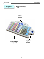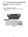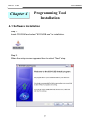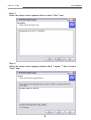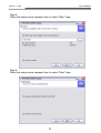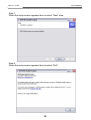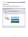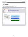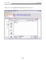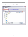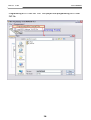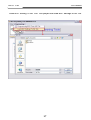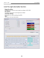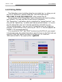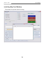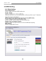
1
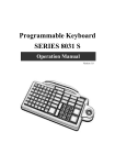
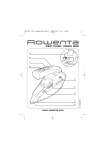
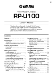
JARLTECH
ISO 9001 Certified
Lead with technology
Win customers with service
Programmable Keyboard
JP8031 USB SERIES
Version: 1.0
OPERATION
MANUAL
JP8031 USB
User Manual
This equipment has been tested and found to comply with the limits for Class
A digital device. Pursuant to Part 15 of the FCC Rules. These limits are
designed to provide reasonable protection against harmful interference in a
residential installation. This equipment generates, uses, and if not installed
and used in accordance with the instructions may cause harmful interference
will not occur in a particular installation. If this equipment does cause
harmful interference to radio or television reception, which can be determined
by turning the equipment off and on. The user is encouraged to try correct
interference by one or more of the following measures:
- Reorient or relocate the receiving antenna.
- Increase the separation between the equipment and receiver.
- Connect the equipment into an outlet on a circuit different from that to which
the receiver is connected.
- Consult the dealer or an experienced radio/TV technician for help. This
booklet is available from the U.S. government Printing Office, Washington, DC
20402, Stock NO.004-000-00345-4.
CAUTION: Any changes of modifications not
expressly approved by the grantee of this device
could void the user’s authority to operate the
equipment.
Operation is subject to the following two conditions:
(1) This device may not cause harmful interference.
(2) This device must accept any interference received including interference
that may cause undesired operation.
1
JP8031 USB
User Manual
Table of Contents:
Chapter 1
Specification Introduction .............................................................4
Chapter 2
Appearance .....................................................................................5
Chapter 3
Hardware Installation......................................................................6
Chapter 4
Programming Tool Installation
4-1. Software Installation..................................................................7
4-2. Main Screen............................................................................11
4-3. ToolBars..................................................................................12
4-4. Key Board Setting............................................................................18
4-4-1. Key Map Button Setting................................................19
4-4-2. Common Setting...........................................................20
4-4-3. KeyLock Level Setting..................................................21
4-4-4. The Right Side Button Fuction......................................22
4-4-5. String Editer..................................................................23
4-4-6. Key Map Test Window..................................................24
4-5. MSR Setting
4-5-1. Main Setting..................................................................25
4-5-2. MSR Right side Button Fuction.....................................26
4-5-3. Track 1~3 Setting..........................................................27
4-5-4. MSR ISO Standard Setting...........................................28
4-6. KeyLock Setting
4-6-1. Main Setting..................................................................29
4-6-2. KeyLock Right Side Button Fuction...............................30
2
JP8031 USB
User Manual
Table of Contents:
4-7. AUX RS232 Setting
4-7-1. Main Setting..................................................................31
4-7-2. AUX RS232 Right Side Button Fuction.........................32
4-8. AUX PS/2 Setting
4-8-1. Main Setting..................................................................33
4-8-2. AUX PS/2 Right Side Button Fuction............................34
4-9. Firmware Update...............................................................................35
Appendix I
Specifications...............................................................................37
Appendix II
Troubleshooting...........................................................................38
3
JP8031 USB
Chapter 1
User Manual
Specification Introduction
The Jarltech 8031 programmable keyboards have been
specially designed for use with personal computers or
terminals in point-of-sale and industrial applications. This
manual describes how to connect the Jarltech keyboard to
your system, how to design a keyboard layout which meets
your special requirements, and how to install your
keyboard layout into the Jarltech keyboard. There are two
model of 8031.
One is a tactile keyboard with seven rows and fifteen
columns for a maximum of105 keys; another emulates for
QWERTY keyboard layout. Both of them are with single,
double, and quadruple key caps. For the keyboard layout,
key function sand key data strings are completely
programmable.
Each keyboard is capable of two concurrent keyboard
maps with switching between the maps controlled by one
designated key. Go to Appendix I for picture reviewing.
JP-8031 is set simulation the windows standard
keyboard, connected to the usb port without driver. AUX
KB port can connect standard PS/2 keyboard, and AUX
RS232 port can connect any external RS232 devices (e.g.,
bar code scanner) and transmitting that data to a host
computer via either the keyboard wedge or an RS232
interface.
4
JP8031 USB
User Manual
Chapter 2
Appearance
MSR
Module
KeyLock
Module
Programmable
keyboard
5
JP8031 USB
Chapter 3
User Manual
Hardware Installation
Connect keyboard to computer:
Please connect 8031 usb cable computer usb port.
(Diagram 3.1)
USB Cable
Diagram 3.1
6
JP8031 USB
Chapter 4
User Manual
Programming Tool
Installation
4-1 Software Installation
Step 1.
Insert CD-ROM and select "8031USB.exe" to installation.
Step 2.
When the setup screen appears then to select "Next" step.
7
JP8031 USB
User Manual
Step 3.
When the setup screen appears then to select "Next" step.
Step 4.
When the setup screen appears please select "I agree.."" then to select
"Next" step.
8
JP8031 USB
User Manual
Step 5.
When the setup screen appears then to select "Next" step.
Step 6.
When the setup screen appears then to select "Start" step.
9
JP8031 USB
User Manual
Step 7.
When the setup screen appears then to select "Next" step.
Step 8.
When the setup screen appears then to select "Exit".
10
JP8031 USB
User Manual
4-2 Main Screen
After the opening program will appear under the plan is the main screen.
The next steps will introduce you to use various functions.
11
JP8031 USB
User Manual
4-3 Tool Bars
New: This project can create a new INF file.
12
JP8031 USB
User Manual
Open INF File: This project can open your choice of INF file.
13
JP8031 USB
User Manual
Save : This project can save your settings to INF file.
14
JP8031 USB
User Manual
Save As : This project can save as your settings to new INF file.
15
JP8031 USB
User Manual
Programming 8031 From INF File: This project can programming 8031 from
INF file.
16
JP8031 USB
User Manual
Load 8031 Setting To INF File: This project can load 8031 settings to INF file.
17
JP8031 USB
User Manual
4-4 Keyboard Key Map Setting
Click the Map 1 button on keyboard page's Key Map Setting , will present
map1 105 pressed key set.
18
JP8031 USB
User Manual
4-4-1 Key Map Button Setting
Click the button will enter the internal settings.
19
JP8031 USB
User Manual
4-4-2 Common Setting
Click Sound:
This setting allows user enable click sound of keys.
Key Repeat:
This setting allows user enable keys repeating speed.
Map Change:
The 8031 has two maps for designs. This keyboard allows use defining a key to switch
maps; once a key be enabled for map changing function, then, the keyboard map will be
changed from map1 to map2 when press this key.
Delay time for each char:
When user scrolling the scale, the key string output speed between characters.(0 ~ 2.55
Sec.).
20
JP8031 USB
User Manual
4-4-3 KeyLock Level Setting
When the optional KeyLock Module be installed, this setting allows user
define key lock's level. i.e. when you set key #1 to be level 1 and level 2,
then the key#1 can only be used when the keylock be set to level 1 or
level 2 by user's key.
Note: Jarltech JP-8031 allow user to set keylock level for 6 levels.
21
JP8031 USB
User Manual
4-4-4 The right side button function
Single Key Write:
This Button is for write the current single key settings to 8031 USB.
Set Default:
This Button is for set the current single key to default.
Load Key Setting:
This Button is for load key settings from 8031.
Test:
This button is for show test window.
22
JP8031 USB
User Manual
4-4-5 String Editer
The field allows users to define string for one single key. i.e. when you set
key #1 as "Welcome to Jarltech Web Site", then the output will be "
WELCOME TO JARLTECH WEB SITE" after pressed key #1.
Above buttons of the"String Editor" field in the picture are tools for editing
key contents. You may use them to edit string or characters.
The "Special key" is as bellow, which is designed for "special function", you
may use the "special key " to define each key as picture's below. i.e. In your
key #1 setting field, click <F1> from the special key and add it to your
"current string property", after you write it to map(you may use "single key
program" to write data of a key), press key #1. the <F1> function appears as
QWERTY PC keyboard behavior.
You may also set "ALT" and "Shift" functions key On/Off to fit your expect.
In keyboard mode, the capital characters cannot be type on the field, and you
may click "Shift ON" before the string to set them on, i.e: <shift-on>
1234<shift-off>5678, The result will be : !@#$5678
23
JP8031 USB
User Manual
4-4-6 Key Map Test Window
This window can provide users for testing.
24
JP8031 USB
User Manual
4-5 MSR Setting
4-5-1 Main Setting
Error Beep Sound:
Enable / disable sound when MSR reading error.
Prefix / Suffix:
Enable or disable prefix / suffix for MSR data
When the check box on, you can edit the prefix / suffix,every fields in up to 7 characters.
Note: The format of output data is:
[MSR Prefix] [Track1 data] [Track2 data] [Track3 data] [MSR Suffix]
Track 2 Shows Credit Card Number Only:
Enable or disable Track 2 Shows Credit Card Number Only.
Enable Caps lock When Output:
Enable or disable the Caps Lock fix to on when the MSR data outputting.
MSR Enable:
Enable or disable MSR Function.
25
JP8031 USB
User Manual
4-5-2 MSR right side button function
MSR Write:
This Button is for write the data settings to 8031 MSR.
Set Default:
This Button is for set the data to default.
Load Key Setting:
This Button is for load the setting from MSR device.
Test:
This button is for show test window.
26
JP8031 USB
User Manual
4-5-3 Track1~3 Setting
Beep Sound
Enable / disable sound when MSR reads the data of card track.
Prefix / Suffix
Enable or disable prefix / suffix for the data of card track.
Start Sentinel
Enable / Disable track start sentinel
(Track 1 start sentinel is “% “, Track 2 / 3 start sentinel is “; “ )
End sentinel
Enable / Disable track end sentinel
(The end sentinel is “? “ for all tracks)
LRC sentinel
Enable / Disable the LRC sentinel is the checksum character for the data of card track.
Left to Right decode and Right to Left decode
You can make choice to decide the user to swipe card and read data only from left to
right or from right to left or both ways
i.e: Track1 data output.
[Track1 Prefix][Start][Track1 Data][END][LRC][Track1 Suffix]
Track2 & Track3 so on..
27
JP8031 USB
User Manual
4-5-4 MSR ISO Standard Setting
For the ISO standard field settings, you need to set the check box of "Field
Splitting Enable" for ON, then the data of card track will be outputted and
follow the ISO standard fields.
You can set the "Send CR" or/and "Send LF" for every ISO fields.
Block Format
i.e: Track1 data output when ISO Field Splitting Enable.
[Additional Data][CC/NAME Data][FC/PAN Data][CR][LF]
Track2 &Track3 so on..
28
JP8031 USB
User Manual
4-6 KeyLock Setting
4-6-1 Main Setting
Beep Sound
Enable / disable sound when turn key.
Prefix / Suffix
Enable or disable prefix / suffix for KeyLock module.
Auto response key level when turn key
Enable or disable when turn key will auto response key level.
Enable
Enable or Disable KeyLock.
29
JP8031 USB
User Manual
4-6-2 KeyLock Right Side Button
Function
KeyLock
Write:
This Button is for write the settings to keylock.
Set Default:
This Button is for set the data to default.
Load Setting:
This Button is for load the setting from device.
Test:
This button is for show test window.
30
JP8031 USB
User Manual
4-7 AUX RS232 Setting
4-7-1 Main Setting
Buffer Full Warning Sounds
Enable / disable sound when buffer full warning.
Prefix / Suffix
Enable or disable prefix / suffix .
Enable
Enable or Disable AUX RS232.
31
JP8031 USB
User Manual
4-7-2 AUX RS232 Right Side Button Function
RS232 Write:
This Button is for write the settings to AUX RS232.
Set Default:
This Button is for set the data to default.
Load Setting:
This Button is for load the setting from device.
Test:
This button is for show test window.
32
JP8031 USB
User Manual
4-8 AUX PS/2 Setting
4-8-1 Main Setting
Buffer Full Warning Sounds
Enable / disable sound when buffer full warning.
Prefix / Suffix
Enable or disable prefix / suffix.
Enable
Enable or Disable AUX PS/2.
33
JP8031 USB
User Manual
4-8-2 AUX PS/2 Right Side Button Function
PS/2 Write:
This Button is for write the settings to AUX PS/2.
Set Default:
This Button is for set the data to default.
Load Setting:
This Button is for load the setting from device.
Test:
This button is for show test window.
34
JP8031 USB
User Manual
4-9 Firmware Update
Special Note:
The 8031 usb provides new features update or modification
from the programming tool, please visit Jarltech web site or
contacts the suppliers for the information.
Step 1.
When you click "Open File" button will pop up the window, select the BIN file
then click "Open".(Picture on the "SS-8031001-00.bin" is an example)
35
JP8031 USB
User Manual
Step 2.
When the picture show on F/W Version after the press "Flash Firmware"
button to update.
Note:
Please do not power off the 8031 or removal the usb cable
when updating firmware.
36
JP8031 USB
User Manual
Appendix I
NO
Specifications
Item
Descriptions
1
Model 8031
Keyboard
• Tactile keyboard
• 7 rows x 15 columns
• Cherry keyswitch
• ABS plastic key caps
• Single, dual and quadruple key caps available
• User-definable key layout
2
Power
Requirements
•USB interface: +5V DC from host computer usb port
3 Physical
4
Communication
Ports
5 LED indicator
• Dimensions: 330mm (L) x 195mm (W) x 55mm (H)
• Weight: 1170g
• One USB port
• LED1 Green -- Power ON -- MAP1 ON
• LED2 Red -- MAP2 ON
• LED2 Green -- Caps Lock ON
37
JP8031 USB
User Manual
Appendix II Troubleshooting
1. Q : Why is there a period of blank time before the "beep"
indication of successful programming?
A : The software has to initialize the download data to keyboard
during this period, so please wait some seconds.
2. Q : Why we can not program this 8031 keyboard through the
USB port?
A : 1. Check if your connection of hardware is correct.
2. Check if your setting in 8031 programming tool is correct.
3. Q : How to program a guard key correctly?
A : For Programming a quad key, please program one of the four
keys with data only and disable the other three keys. The doublekey is set by the same method, Or
to programming a double key or quad key with same data for every
keys.
Jarltech International Inc.
Taipei Office: 3F, No.1, Lane 538, Chunng Cheng Road, Hsin Tien City,Taipei ,Taiwan ROC
Web site: www.jarltech.com.tw
E-mail: [email protected]
38