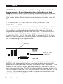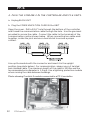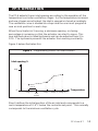
1
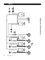
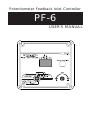
Potentiometer Feedback Inlet Controller
PF-6
USER'S MANUAL
TABLE OF CONTENTS
PRECAUTIONS ........................................................ 3
FEATURES .............................................................. 4
LOCATION OF THE CONTROLS ................................. 5
CONTROLLER STATUS LEDS ................................................... 5
INTERNAL SWITCHES ............................................................. 6
INSTALLATION PROCEDURE ..................................... 7
PF-6 OPERATION ....................................................15
OVER-OPENING STAGE (OPTIONAL) ....................................... 18
BEFORE CALIBRATING THE REFERENCE POINTS ....................... 20
CALIBRATION PROCEDURE ................................................... 21
CONTROLLER FUNCTIONS ......................................23
ACTUAL OPENING ............................................................... 23
IDENTIFICATION NUMBER ..................................................... 24
OVER-OPENING SETTING ...................................................... 25
PROGRAMMING .................................................................. 26
ALARMS - READOUT ............................................................ 27
ALARMS - HIGH .................................................................. 28
ALARMS - LOW ................................................................... 29
ROOM TEMPERATURE .......................................................... 30
TROUBLESHOOTING GUIDE .....................................31
TECHNICAL SPECIFICATIONS ...................................32
FACTORY SETTINGS ...............................................33
FOR CUSTOMER USE
Enter below the serial number located on the side of the controller
and retain this information for future
reference.
Model number
Serial number
2
PF-6.rev.07
PF-6
PRECAUTIONS
Fuses at the input and outputs of the controller adequately protect
its circuitry in the case of an overload or overvoltage. However, we
recommend that you install an additional protection device on the
controller's supply circuit to prolong the life of the controller.
The room temperature of the room in which the controller is located
MUST ALWAYS REMAIN BETWEEN 32° AND 104°F (0° AND
40°C).
To avoid exposing the controller to harmful gases or excessive
humidity, it is preferable to install it in a corridor.
DO NOT SPRAY WATER ON THE CONTROLLER
PF-6.rev.07
3
FEATURES
The PF-6 is an electronic device used for air inlet control in livestock
buildings. In combination with an environment controller, the PF-6
coordinates the movement of the air inlets with the operation of the fans
using a potentiometer located on the panel drive. Additional units can be
connected to the PF-6 for an independent control of additional air inlets.
The main features of the PF-6 are as follows:
DIGITAL DISPLAY
A digital display shows the operation parameters and alarm messages.
PILOT LIGHTS
Pilot lights indicating the state of outputs allow you to monitor the
operation of the system from a distance.
ALARM OUTPUT
The controller generates an output signal that will activate any alarm
system in the case of various operation problems.
HYSTERESIS
A hysteresis prevents the air inlet panels from oscillating around the
desired position when small variations in fan speed occur.
PERMANENT MEMORY
Settings are retained in memory even in the event of a power failure.
OVERLOAD AND OVERVOLTAGE PROTECTION
Fuses located at the input and outputs of the controller protect its
circuitry in the case of an overload or overvoltage.
COMPUTER CONNECTION
A computer can be connected to the PF-6 to centralize information
management and provide monitoring and datalogging possibilities.
4
PF-6.rev.07
LOCATION OF THE CONTROLS
STATUS LEDS
PUSH-BUTTON
FUNCTION
SELECTOR
ADJUSTMENT
KNOB
CONTROLLER STATUS LEDS
LED
ME AN IN G
OPEN
TU R N S O N W H E N TH E P F - 6 O P E N S TH E A IR IN L E T PA N E L S .
CLOSE
TU R N S O N W H E N TH E P F - 6 C L O S E S TH E A IR IN L E T PA N E L S .
% OPENING
T U R N S O N W H E N T H E N U M B E R D IS P L A YE D IS T H E A IR IN L E T
O P E N IN G P E R C E N TA G E .
ADJUST
OPENING
T U R N S O N W H E N T H E P F - 6 IS WA IT IN G F O R YO U T O A D J U S T T H E
A IR IN L E T O P E N IN G .
C A L I B R AT I O N
TU R N S O N W H E N P F - 6 IS IN C A L IB R ATIO N M O D E . F L A S H E S W H E N
C A L IB R ATIO N IS F IN IS H E D A N D S W ITC H # 7 IS S TIL L IN O N
P O S ITIO N .
LOCKED
TURNS ON WHE N THE PA RA ME TE RS A RE LOC K E D A ND C A NNOT
B E A D JUS TE D
ºC / ºF
T U R N S O N W H E N T H E N U M B E R D IS P L A YE D IS IN F A H R E N H E IT
D E G R E E S . F L A S H E S W H E N T H E N U M B E R D IS P L A YE D IS IN
C E L S IU S D E G R E E S .
ALARM
TU R N S O N W H E N A N A L A R M IS D E T E C T E D .
PF-6.rev.07
5
PF-6
ON
INTERNAL SWITCHES
1
2
3
4
5
6
7
8
9 10 11 12
The internal switches are located on the inside of the front cover. When
the controller is shipped from the factory, all the switches are set to
OFF.
6
#
OFF
ON
1
UNLOC KED PARAMETERS
LOC KED PARAMETERS
2
FAHRENHEIT D EGREES
C ELSIUS D EGREES
3
SUMMER PROGRAM
WINTER PROGRAM
4
D ISABLE TEMPERATURE
ALARMS
ENABLE TEMPERATURE
ALARMS
5
NO TEMPERATURE
PROBE
TEMPERATURE PROBE
PRESENT
6
SLAVE UNIT
PRIMARY UNIT
7
END C ALIBRATION
START C ALIBRATION
8
OVER-OPENING:
NORMAL MOD E
OVER-OPENING:
D ROP MOD E
9
RESERVED
10
RESERVED
11
RESERVED
12
RESERVED
PF-6.rev.07
INSTALLATION PROCEDURE
EQUIPMENT LIST
Integrating an air inlet control system into your ventilation system
requires the following equipment:
a Comlink-2 communication module added to your controller
a PF-6 controller for each air inlet panel (up to 100 in all)
an alarm system (optional)
a DC power supply (optional)
a power unit equiped with a 10 turn potentiometer (> 1 kOhm)
1. MOUNT THE PF-6
Remove the four screws in the front cover and lift the cover. Remove
the black caps located on the three mounting holes. Mount the enclosure
to the wall using three screws. Be sure the electrical knockouts are at
the bottom of the enclosure in order to prevent water from entering the
controller. Insert the screws into the mounting holes and tighten. Fasten
the black caps onto the mounting holes.
2. MAKE THE CONNECTIONS
To connect the equipment, refer to one of the two wiring diagrams
enclosed with this user's manual depending on whether you are using an
AC or DC type power unit motor. Also refer to the DC power supply
wiring diagram when using a DC type motor.
PF-6.rev.07
7
PF-6
COMPLETE PF-6 CONTROLLER SETUP
PF-6.rev.07
8
PF-6
Use the electrical knockouts provided at the bottom of the
enclosure. Do not make additional holes in the enclosure.
Set the voltage switch to the appropriate line voltage.
CONCERNING THE ALARM CONNECTION: There are two types of
alarms in the industry. One type activates when current is cut off at its
input, whereas the other activates when current is supplied at its input.
For an alarm of the first type, use the NO terminal as shown on the
wiring diagram. For an alarm of the second type, use the NC terminal.
!
CAUTION
ALL WIRING MUST BE DONE BY AN AUTHORIZED ELECTRICIAN AND MUST COMPLY WITH APPLICABLE CODES,
LAWS AND REGULATIONS. BE SURE POWER IS OFF
BEFORE DOING ANY WIRING TO AVOID ELECTRICAL
SHOCK AND EQUIPMENT DAMAGE.
TEMPERATURE PROBES: If your PF-6 unit is supplied with a temperature probe, connect it to terminal PROBE #1 and set internal switch #5
to ON. Note that the PF-6 will operate with no temperature probes
connected to it. However, the room temperature position on the function selector will not function in this case.
This probe can be extended up to 500ft (150m).
To extend the probe:
Use a shielded cable of outside diameter between 0.245 and
0.260 in (6.22 and 6.60 mm) to ensure the cable entry is liquidtight (the cable dimension must not be under 18 AWG).
It is preferable to solder the cable joint to ensure a proper
contact between the two cables.
Do not ground the shielding.
PF-6.rev.07
9
PF-6
CAUTION : The probes operate under low voltage and are isolated from
the power supply. Be sure the probe cable is isolated from all high
voltage sources. Do not route the probe cable and other power cables
through the same electrical knockout. Do not run the probe cable next to
other power cables. When crossing over other power cables, cross at
90°.
3. CONFIGURE ID AND END-OF-LINE JUMPERS ON
COMLINK-2 CARDS
Each Comlink-2 card used to communicate parameters between PF-6
units and the main controller must have a unique identification number.
This number is configured using jumpers on the card and should be
assigned before plugging the card into each unit. To do this, use the
three jumpers (marked X100, X10 and X1) on the card (i.d. numbers can
go from 0 to 199). Use X1 for units, X10 for tens and X100 for hundreds. In each case, place the black jumper horizontally over the two
pins corresponding to the digit required.
ID JUMPERS
END OF LINE
JUMPERS
The PF-6 network operates on two communication lines. One line links
the PF-6 units together to the main controller and the other line links
temperature controllers to a computer (this second line is optional). Two
jumpers on the Comlink-2 card are used to identify the end of line for
each communication line. The PF-6 communication line uses jumper JP5
and the computer line uses JP4. Use pins 2 and 3 for YES and pins 1 and
2 for NO. The following diagram shows a typical connection with the
appropriate jumper configurations.
10
PF-6.rev.07
PF-6
PF-6.rev.07
11
PF-6
4. PLUG THE COMLINK-2 IN THE CONTROLLER AND PF-6 UNITS.
a. Unplug EACH UNIT
b. Plug the COMMUNICATION CARD IN the UNIT
Open the cover. Drill a 5/16" hole through the bottom of the controller
and thread the communication cable through the hole. Use the grommet
provided to secure the cable. Connect the cable to the terminals of the
communication card as shown below. When connecting two cable ends
together, solder the joint and use a heat shrink to ensure a proper
contact.
Line-up the module with the connector and insert it in the upright
position (see photo below). For communication, always use a 1 twisted
pair shielded cable. The maximum length of the cable is 3000m and the
recommended wire diameter is 1.0mm. Use a lightning protection module
when running the cable between buildings.
Photo showing Comlink-2 module connected to a PF-6 controller.
Comlink-2
12
PF-6.rev.07
PF-6
Photo showing Comlink-2 module connected to a TC5 controller.
Comlink-2
!
CAUTION
!
CAUTION
Be sure the communication cable is isolated from all high
voltage sources and fluorescent lights. Do not route the
communication cable and power cables through the same
electrical knockout. Do not run the communication cable
next to power cables. When crossing power cables, cross
at 90°.
DO NOT GROUND THE SHIELD WIRE!
DISCONNECT THE POWER SOURCE BEFORE CONNECTING THE COMMUNICATION CABLE.
5. CONFIGURE THE PF-6'S AS PRIMARY / SLAVE
If your installation requires more than one PF-6 unit for independent
control of different air inlets, one of the PF-6's will be configured as the
primary unit and the others will be configured as slaves. Up to 99 slave
units can be connected in this way. When programming the PF-6's, the
slave units take their reference temperature from the primary unit and
are programmed after the primary unit has determined the next
reference point. The default setting at the factory is SLAVE.
Set internal switch #6 to ON for the primary unit or OFF for a
slave unit.
PF-6.rev.07
13
PF-6
6. VERIFY PF-6 OPERATION
Power the PF-6 and set the function selector to MANUAL MODE
position. Use the adjustment knob to select OPN to open, CLO to
close or OFF to stop the winch.
Verify motor operation:
Open and close the air inlet panels using the open-close switch.
The air inlet panels should open when the switch is set to OPEN
and close when the switch is set to CLOSE. If the air inlet panels
move the opposite way, the motor operates in the wrong
direction. Turn off the power and reverse the wires connected
to terminal #3 and #4. Verify that the motor now operates in
the right direction.
Verify limit positions of air inlet panels:
Fully close the air inlet panels using the open-close switch. Adjust
the power unit limit switch to this position in order to prevent the
power unit from closing further. Fully open the air inlet panels
using the open-close switch. Adjust the power unit limit switch
to this position in order to prevent the power unit from opening
further.
14
PF-6.rev.07
PF-6 OPERATION
The PF-6 adjusts the air inlet opening according to the operation of the
temperature controller ventilation stages. As the temperature increases
and new stages are activated, the inlet is opened or closed accordingly.
The ventilation curve is divided into steps and the user must program a
new air inlet position for each step.
When the actuator isn't moving, a minimum opening or closing
percentage is necessay so that the actuator can start to move. This
user-defined value is called hysteresis and can be adjusted from 2 to
10%. The hysteresis prevents the actuator from moving constantly.
Figure 1 below illustrates this.
Figure 1 Programming Points for Inlet Position
Inlet opening %
○
○
○
○
Step 0
Set
point
○
○
○
○
○
○
○
0.4°F
○
0
○
○
○
○
○
○
○
○
○
○
○
○
○
○
○
○
○
○
100
Step 1 Step 2 Step 3
Temperature
Step 0 defines the initial position of the air inlet and corresponds to a
room temperature of 0.4°F below the controller set point. This normally
corresponds to the minimum ventilation cycle.
PF-6.rev.07
15
PF-6
The other steps follow according to the ventilation curve. A step is
added each time a new stage is activated by the temperature controller.
Figure 2 below shows an example of this.
Figure 2 Ventilation Curve with Constant-Speed Stages Only
Ventilation
Stage 1
○
○
○
○
○
○
○
○
○
○
○
○
○
○
○
○
○
○
○
Step 2
Step 1
○
○
○
Stage 2
○
○
○
○
○
○
○
○
Step 0
0.4oF
(0.2oC)
DIFFERENTIAL
STAGE 1
DIFFERENTIAL
STAGE 2
Room
Temperature
Temperature
Set Point
This example has two constant-speed ventilation stages. Step 1
corresponds to the activation of the first ventilation stage at
“ temperature set point + differential 1 ”. Step 2 corresponds to the
activation of the second ventilation stage at “ temperature set point +
differential 1 + differential 2 ”.
16
PF-6.rev.07
PF-6
A step is also added when the speed on a variable speed stage reaches
100% without activating a new stage. Figure 3 below illustrates this.
In this example, a step is added when the first ventilation stage reaches
full speed at “ temperature set point + bandwidth 1 ” even though no
new stages are activated at this point. This step is called “ Step 1 Hi ” the step number is not increased as we are dealing with the same
ventilation stage as Step 1. Step 2 corresponds to the activation of
Stage 2 and Step 2 Hi defines the point where Stage 2 reaches full
speed.
Figure 3 Ventilation Curve with Variable-Speed Stages
Ventilation
○
○
○
○
○
○
○
○
○
○
○
○
○
○
○
○
○
○
○
○
○
○
○
○
○
Step 3
○
○
○
○
○
○
○
○
○
○
○
Step 2
Step 2
Hi
○
○
○
○
○
○
○
○
○
○
○
○
○
○
Step 1
○
○
○
○
○
○
○
○
○
○
○
○
○
○
○
○
○
○
○
○
○
○
○
○
○
○
○
○
○
Step 0
BANDWIDTH
STAGE 1
OFFSET
BANDWIDTH
STAGE 2
○
○
○
○
0.4oF
(0.2oC)
○
○
Min.
Ventilation
○
○
Stage 1
○
○
Step1 Hi
○
○
Stage 2
○
○
○
○
○
Stage 3
Room
DIFFERENTIAL
STAGE 3
Temperature
Temperature
Set Point
PF-6.rev.07
17
PF-6
OVER-OPENING STAGE (OPTIONAL)
A supplementary stage can be calibrated in order to continue opening the
air inlet beyond the last temperature controller ventilation stage. This
supplementary stage is optional. It is used to direct the airflow more
efficiently during periods of warm weather. When all the reference
points of the temperature controller ventilation stages have been calibrated, the PF-6 allows you to specify a temperature bandwidth as well
as a percentage of air inlet opening for the supplementary stage.
Normal Mode:
To use normal mode, set internal switch #8 to OFF. The PF-6 gradually
opens or closes the panels in a linear fashion as the room temperature
rises above the last reference point temperature. The air inlet opening
reaches the percentage specified for the over-opening when the room
temperature is equal to "temperature of the last reference point +
over-opening bandwidth". The percentage of air inlet opening is based on
the smallest and greatest air inlet openings calibrated for the controller
stages. The smallest value defines an air inlet opening of 0% and the
greatest value defines an air inlet opening of 100%.
Inlet
Opening
Over-Opening
Inlet Opening
○
○
○
○
○
○
○
○
○
○
○
○
○
○
○
○
○
○
○
○
○
○
○
○
○
○
○
○
○
○
○
Last Stage
Inlet Opening
○
○
○
○
○
○
○
○
○
○
○
○
○
○
○
○
○
○
○
Min.Opening
○
○
○
○
○
○
○
CONTROLLER STAGES OVER-OPENING
BANDWIDTH
Temperature
Set Point
18
PF-6.rev.07
Room
Temperature
PF-6
Drop Mode:
To use drop mode, set internal switch #8 to ON. The PF-6 maintains the
inlet opening at the value of the last controller stage as the temperature
rises above the last reference point temperature. When the temperature
reaches "temperature of the last reference point + over-opening bandwidth", the inlet is opened to the over-opening percentage. When the
temperature drops by 0.5°F, the inlet returns to the opening of the last
controller stage.
Inlet
Opening
0.5°F
Over-Opening
Inlet Opening
○
Last Stage
Inlet Opening
○
○
○
○
○
○
○
○
○
○
○
○
○
○
○
○
○
○
○
○
○
○
○
○
○
○
○
○
○
○
○
○
○
○
○
○
○
○
○
○
○
○
Min.Opening
○
○
○
○
○
○
○
○
CONTROLLER STAGES OVER-OPENING
BANDWIDTH
Room
Temperature
Temperature
Set Point
PF-6.rev.07
19
PF-6
BEFORE CALIBRATING THE REFERENCE POINTS
When to calibrate the reference points
It is preferable to calibrate the reference points when the room
is empty because adjusting the air inlet openings will cause
drafts.
Operation of the temperature controller
In order to properly simulate the operation of the ventilation
stages, adjust all the parameters at the same value that would
be used at the first day of a new breeding.
If variable fans are used to ensure minimum ventilation, adjust
the minimum speed of the fans at the same speed that would
be used at the first day of a new breeding.
Be sure that the circuit breakers at the service panel and all
other protection devices are in a position such that the fans can
be activated.
Air inlet panel position
Install a static pressure measuring device or determine in
advance the position required at each reference point by
calculating, according to the fan airflow, the opening that will
maintain the desired air speed at the inlet.
PF-6 internal switches:
Set the lock switch to OFF in order to unlock the automatic
mode.
Using the season switch, select the season you want to
program.
20
PF-6.rev.07
PF-6
CALIBRATION PROCEDURE
This section describes the calibration procedure for a primary/slave
installation. Slave units allow an independent control of additional air
inlets. The PF-6 leads you through the procedure by gradually increasing
the room temperature to simulate the complete operation of the
temperature controller from the minimum ventilation cycle up to the last
ventilation stage. Each time the room temperature reaches a step point
temperature, the PF-6 waits for you to adjust the air inlet panels to the
required position for this step point. You can determine the required
position either by measuring the static pressure in the room or by
calculating the opening that will maintain the desired air speed at the
inlet based on the fan airflow.
Note that when you advance to a new step point in the sequence, the
PF-6 can position the inlets according to the position currently stored in
memory. Minor adjustments can then be made to an existing calibration.
The calibration is saved only at the end of the sequence when the word
END is displayed.
1. Set internal switch #7 to ON on all PF-6 units. If the calibration led
on a unit is flashing, set switch #7 to OFF and then back to ON. Air
inlets are completely closed and the display shows CLO. Then OFF is
displayed, alternating with “S. 0” (step 0). The temperature
controller operates according to the set point value minus 0.4°F
0.2°C).
STEP 0
0.4 oF
(0.2oC)
Room Temperature
Temperature Set Point
2. Use the adjustment knob to manually adjust the opening value on
each PF-6 unit for this reference value – CLO to close, OPN to open,
AUT to retrieve the previously calibrated position.
PF-6.rev.07
21
PF-6
3. When finished adjusting, use the adjustment knob to return to the off
position.
4. Press the push-button on the primary PF-6 unit to record air inlet
positions for all PF-6 units (note that the push-button on slave units is
disabled during calibration).
5. The temperature controller increases the temperature to the next
step. A new step is created either when a new stage turns on or
when a variable stage reaches maximum speed. When the second
case occurs, the step value is not incremented and the PF-6 displays
“Hi”.
6. Repeat steps 2, 3 and 4 until the last stage on the controller is
reached.
7. When the last stage has been calibrated, the temperature controller
increases the temperature to 120°F to calibrate the over-opening
step (the user can also press the push-button for 5 seconds to
advance to this step). Use the adjustment knob to manually adjust
the opening value on each PF-6 unit for the over-opening step – CLO
to close, OPN to open, AUT to retrieve the previously calibrated
position, and OFF to finish adjusting.
Last Step
Inlet Opening
CONTROLLER STEP
Over-Opening
Inlet Opening
OVER-OPENING
DIFFERENTIAL
Room
Temperature
Temperature
Set Point
8. Press the push-button on the primary PF-6 to finish the calibration.
If this is not done, none of the calibrated openings will be saved.
Each PF-6 displays End.
9. Set internal switch #7 to OFF on all PF-6 units.
22
PF-6.rev.07
CONTROLLER FUNCTIONS
ACTUAL OPENING
This function gives a readout of the
current air inlet opening as a
percentage from 0 % to 100 %
(limit values are determined during
the calibration). This function also
allows to modify the needed
hysteresis value to activate the
actuator. Minimum and maximum opening values can also be displayed.
Note that this function is not available during calibration.
Settings
The current opening is displayed as a percentage.
Turn the adjustment knob one notch to the right. The maximum
value is displayed alternating with the letters "Hi".
Turn the adjustment knob one notch to the left. The current
opening is displayed.
Turn the adjustment knob one notch to the left. The minimum
value is displayed, alternating with the letters "Lo".
Press and hold the push-button during 5 seconds. The hysteresis
is displayed alternating with the letters "HYS".
Use the adjustment knob to adjust the hysteresis to the desired
value.
Note :
If you let the display flash for more than 10 seconds, the controller
resets the minimum and maximum opening values currently in memory.
In other words, the two values are reset to the current opening value. To
avoid resetting minimum and maximum values, return to the current
opening display using the adjustment knob (clockwise or
counterclockwise) before the 10 second delay has elapsed.
PF-6.rev.07
23
PF-6
IDENTIFICATION NUMBER
This function displays the identification number of the PF-6 along with its
primary/slave status. The identification number is set using jumpers on
the printed circuit board (see chapter on installation). Note that this
function is not available during calibration
Settings
The identification number is displayed, alternating with "ID"
and "PRI" or "SLA" for a primary or slave unit.
24
PF-6.rev.07
PF-6
OVER-OPENING SETTING
The over-opening bandwidth is
used to open the air inlet further
when the last reference point
temperature has bean reached.
It can be adjusted from 0.5 to
20°F (0.3 to 11.1°C). Note that
this function is not available during calibration.
Last Stage
Inlet Opening
Over-opening
Inlet Opening
CONTROLLER STAGES OVER-OPENING
BANDWIDTH
Room
Temperature
Temperature
Set Point
Settings
The bandwidth is displayed, alternating with the letters "BD".
Use the adjustment knob to adjust the bandwidth to the desired
value.
PF-6.rev.07
25
PF-6
PROGRAMMING
This function is used to calibrate
the air inlet opening for each
calibration step. A step is
created each time a new stage
is activated or whenever the
speed on a variable speed stage
reaches 100% without
activating a new stage.
Settings
The step number is displayed as "S.X" where X is the step
number (0 to 28), alternating with the air inlet opening. When
the step correspond to a speed of 100 % on a variable stage
with no new stage activated, "Hi" is displayed in the alternating
sequence and the step number is not incremented.
When calibrating, use the adjustment knob to manually adjust
the opening value : OFF to stop adjusting, CLO to close, OPN
to open and AUT to retrieve the previously calibrated position.
Press the push-button to calibrate the next step. The last step
is the over-opening stage.
Press the push-button after the over-opening stage to end the
calibration. "END" is displayed. If this is not done, none of the
calibration steps will be stored in memory. Set internal switch
#7 to OFF to end the calibration.
After a calibration, the opening of each point can be edited.
26
PF-6.rev.07
PF-6
ALARMS - READOUT
When an alarm occurs, the PF-6
activates the alarm contact and
turns on the alarm pilot light. The
alarm readout function displays all
currently outstanding alarm
situations. This function is not
available during calibration.
ALAR M
C OD E
MEAN IN G
AL1
C OMMUNIC ATION BETWEEN THE PF-6 AND THE C ONTROLLER IS D ISRUPTED .
AL2
C ALIBRATION IS NOT VALID .
POTENTIOMETER IS NOT C ONNEC TED PROPERLY.
AL3
THE WINC H TRIED TO OPEN / C LOSE WHILE IT WAS LEANING ON A LIMIT
SWITC H. REC ALIBRATE THE PF-6
THE LIMIT SWITC HES HAVE BEEN D ISPLAC ED . REC ALIBRATE THE PF-6
POTENTIOMETER IS D EFEC TIVE.
AL4
TEMPERATURE PROBE IS D EFEC TIVE OR NOT C ONNEC TED PROPERLY.
AL5
LOW TEMPERATURE ALARM.
AL6
HIGH TEMPERATURE ALARM.
Settings
The display shows "No" alternating with "AL" when no alarms
have been detected. Otherwise, the display shows an alternating sequence of all outstanding alarms as "AL,X" where X is the
alarm number
.
!
CAUTION
If the potentiometer is defective, the PF-6 will operate in
security mode: when the room temperature is 2°F above
the set point, the inlet opens according to the cycle: 5
seconds ON, 120 seconds OFF. When the room
temperature is 2°F below the set point, the inlet closes
according to the same cycle.
PF-6.rev.07
27
PF-6
ALARMS - HIGH
This function is used to adjust the
offset for the high temperature
alarm. The alarm contact is
activated when the room
temperature
exceeds
"temperature set point + high
alarm offset" as shown below.
The offset can be adjusted from
0.5°F to 20°F (0.3°C to
11.1°C). Note that internal switch #4 must be set to ON for this alarm to
be detected. This function is not available during calibration.
T°
HighTemperature Alarm
High Offset
Set Point
Time
Settings
The high alarm offset is displayed, alternating with the letters
"Hi"
Use the adjustment knob to adjust the offset to the desired
value.
28
PF-6.rev.07
PF-6
ALARMS - LOW
This function is used to adjust
the offset for the low
temperature alarm. The alarm
contact is activated when the
room temperature drops below
"temperature set point- low
alarm alarm offset" as shown
below. The offset can be
adjusted from 0.5°F to 20°F (0.3°C to 11.1°C). Note that internal switch
#4 must be set to ON for this alarm to be detected. This function is not
available during calibration.
T°
Set point
Low offset
Time
Low temperature alarm
Settings
The low alarm offset is displayed, alternating with the letters
"Lo"
Use the adjustment knob to adjust the offset to the desired
value.
PF-6.rev.07
29
PF-6
ROOM TEMPERATURE
This function gives a readout of
the current room temperature,
minimum and maximum
temperature values can also be
displayed. Internal switch #5
must be set to ON and a
temperature probe must be
connected for this function to
work. Note that this function is
not available during calibration.
Settings
Turn the adjustment knob one notch to the right. The maximum
value is displayed alternating with the letters "Hi".
Turn the adjustment knob one notch to the left. The current
opening is displayed.
Turn the adjustment knob one notch to the left. The minimum
value is displayed, alternating with the letters "Lo".
Note :
If you let the display flash for more than 10 seconds, the controller
resets the minimum and maximum opening values currently in memory.
In other words, the two values are reset to the current opening value. To
avoid resetting minimum and maximum values, return to the current
opening display using the adjustment knob (clockwise or
counterclockwise) before the 10 second delay has elapsed.
30
PF-6.rev.07
TROUBLESHOOTING GUIDE
PROBLEM
SOLUTION
THERE IS NO
DISPLAY.
THE CIRCUIT BREAKER AT THE SERVICE PANEL IS OFF OR
TRIPPED.
THE WIRING IS INCORRECT.
THE F6 INPUT FUSE IS OPEN.
THE VOLTAGE SELECTOR SWITCH IS IN THE WRONG
POSITION.
THE DISPLAY BOARD INTERCONNECT CABLE IS UNPLUGGED FROM THE POWER SUPPLY BOARD.
THE ROOM
TEMPERATURE
DISPLAYED BY
THE PF-6 SHOWS
SUDDEN VARIATIONS.
A VARIATION IN RESISTANCE IS INDUCED ON THE
SENSOR CONNECTED TO THE PF-6
- BE SURE THE SENSOR IS DRY AND MOVE IT AWAY
FROM DRAFTS AND FROM ANY SOURCE OF RADIANT
HEATING.
THERE IS ELECTRICAL NOISE NEAR THE CABLE OF THE
SENSOR CONNECTED TO THE PF-6.
- DO NOT RUN THE SENSOR CABLE NEXT TO OTHER
POWER CABLES. WHEN CROSSING OTHER POWER
CABLES, CROSS AT 90°.
THE PF-6 ALARM
THE F5 ALARM FUSE IS OPEN.
PILOT LIGHT IS ON
BUT THE ALARM
THE DISPLAY BOARD INTERCONNECT CABLE IS UNIS NOT
PLUGGED FROM THE POWER SUPPLY BOARD.
ACTIVATED.
THE WIRING IS INCORRECT.
THE PF-6 ALARM IS DEFECTIVE.
THE PF-6 IS DEFECTIVE.
- LISTEN TO SEE IF THERE IS A CLICKING SOUND WHEN
THE ALARM PILOT LIGHT TURNS ON. IF THERE IS NO
CLICKING SOUND, THE PF-6 IS DEFECTIVE. CONTACT
YOUR DISTRIBUTOR TO REPAIR THE CONTROLLER.
PF-6.rev.07
31
TECHNICAL SPECIFICATIONS
Supply: - 115/230 VAC (- 18%, + 8%), 50/60 Hz, overload and
overvoltage protection fuse F6-1A fast blow.
- 12 VDC for AC back-up supply, can activate the inlet and alarm if
supplied with DC back-up voltage.
Power unit: 50/60 Hz, 30 VDC, 5A motor output, fuse F1-5A slow blow.
Alarm: ON-OFFoutput, 115/230 VAC, 50/60 Hz, 30 VDC, 3A, fuse F4-3A
slow blow.
Potentiometer: 5kOhms to 10kOhms
Probes: Low voltage ( < 5V), isolated from the supply. Operating range:
-40.0° to 120.0°F(-40.0° to 49°C). Accuracy: 1.8oF (1°C) between
41o and 95oF (5° and 35°C).
Enclosure: ABS, humidity and dust-tight.
32
PF-6.rev.07
FACTORY SETTINGS
PAR AMETER
FAC TORY SETTIN GS
R AN GE OF VALU ES
LOW ALARM
10°F
0.5 - 20°F
0.3 - 11.1°C
HIGH ALARM
12°F
0.5 - 20°F
0.3 - 11.1°C
OVER-OPENING
BAND WID TH
5°F
0.5 - 20°F
0.3 - 11.1°C
PF-6.rev.07
33