1
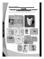
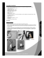
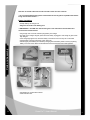
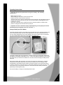
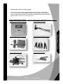
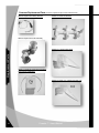
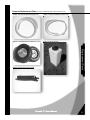
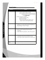
PowerFlo 20™ Parts List/Assembly Instructions/Users Guide ***PLEASE READ ALL INSTRUCTIONS CAREFULLY AND THOROUGHLY*** Owners Manual (Please check to make sure to locate all parts before assembly.) 11/12/2008 PowerFlo ™ -Owners Manual 1 PowerFlo ™ -Owners Manual 2 Table of Contents . I. Parts and Assembly . . . . . . . . . . . . . . . . . . . . . . . . . . . . . . (pages 4-8) II. Operating Instructions . . . . . . . . . . . . . . . . . . . . . . . . . . . . . (pages 9) III. Maintenance/Storage . .. . . . . . . . . . . . . . . . . . . . . . . . . . . . (pages 10-12) IV. Commonly Replaced Parts . . . . . . . . . . . . . . .. . . . . . . . . . (pages 13-15) V. Troubleshooting Guide . . . . . . . . . . . . . . . . . . . . . . . . . . .. (pages 16) VI. Frequently Asked Questions. . . . . . . . . . . . . . . . . . . . . . . . (pages 17) VIII. Warnings . . . . . . . . . . . . . . . . . . . . . . . . . . . . . . . . . . . . . . ..(pages 19) Table of Contents VII. Reconditioning Program . . . . . . . . . . . . . . . . . . . . . . . . . . . (pages 18) (Please check to make sure to locate all parts before assembly.) PowerFlo ™ -Users Manual 3 . Parts List and Assembly PowerFlo20™ ***PLEASE READ ALL INSTRUCTIONS CAREFULLY AND THOUROGHLY*** ***BEFORE BEGINNING ASSEMBLY*** Please be sure all parts listed below are included in your package before beginning assembly. Figure (1) Figure (2) Parts and Assembly Figure (1) Figure (3) Figure (7) Figure (2) Figure (4) Figure (8) Figure (10) 4 Figure (5) Figure (6) Figure (9) Figure (11) PowerFlo™ -Users Manual Figure (12) 4 Assembly Instructions . You should have two large boxes for a complete unit. Contents of the larger box is as follows: • One 2-wheeled hand truck -(Figure 1.) • 20 gal tank-(Figure 2) • Cabinet and two hoses -(Figure 3.) • Manifold and six valves -(Figure 4.) • Battery charger pack – (Figure 5) • Hose Clamp – (Figure 6.) • Battery – (Figure 7) • Wiring Harness – (Figure 8) • (4) mounting tabs with (4) ¼ x 20 hex head bolts, (4) nuts, (4)washers (in zip plastic bag) – inside the cabinet -(Figure 9) • 2 bolts, 2 nuts – ( Figure 10) • Strap – (Figure 11) • Manifold Mounting straps – (Figure 12) • Instructions • Fuse (extra inside cabinet door) Assembly: Cabinet Installation Parts and Assembly • Lay the cart down on a clean dry surface with the foot plate facing down • Use the screws included in the mounting kit bag to attach mounting tabs to the back of the cabinet as shown below (left). Attach cabinet to the rear of the hand truck using the mounting tabs (Figure 9) and screws provided. • Position the cabinet so the four elongated holes on the mounting tabs (Figure 9) match up with the pre-drilled holes in the crossbars on the hand truck. Insert the 1/4x 20 bolts (Figure 9) into each hole through cabinet and hand truck, install washer (Figure 9) , and lock nut (Figure 9) . Tighten all four bolt assemblies. Lock nut PowerFlo ™ -Users Manual 5 Manifold Installation • Stand the cart upright on its wheels placing the manifold with three of the hoses over the front of the top bar • The clear supply hose should be on the right side of the bar looking at the unit from the rear (Fig 13) Parts and Assembly (Figure 13) • Locate the two manifold mounting straps, two 1” bolts, and two nuts (figure 10 on parts page) • Place a strap over each end of the manifold so the straight side of the strap is against the back of the top strap on the cart • Install one bolt through the hole in the top strap in the cart from the front • Place the strap over the protruding bolt squeezing the strap closed just enough to install a nut on the bolt • Repeat for other side • Twist manifold slightly in the straps to make the hoses and manifold level from front to back and securely tighten the nuts 6 PowerFlo™ -Users Manual 6 • Attach short hose from box to barb on manifold with supplied clamp and tighten securely Tank Installation Parts and Assembly • Place the tank on the foot of the cart with the hole in the top on the right side looking at the unit from the front • Insert the braided suction hose through the hole pushing it into the tank until it is at or near the bottom of the tank • Locate the strap and wrap it around the unit aligned just below the cabinet. • Pull the strap tight and tuck the excess strap between the tightened strap and the tank PowerFlo ™ -Users Manual 7 Note: Do not overfill water tank as water will leak out the vent hole in the lid! ***It is recommended that the system is flushed with at least 10 gallons of potable water before being used for the first time*** Battery Installation • Unwrap battery and charger unit • Plug wire connectors onto battery post ***IMPORTANT*** The RED wire with the fuse goes on the red terminal and the white wire connects to the black terminal Parts and Assembly • Plug charger into a 120 volt outlet and plug battery into charger • The light on the charger will glow yellow when the battery is plugged in and change to green when fully charged • If the charger light glows red, check the battery connections to be sure they are not reversed • Charge battery overnight (check that green light is lit) • After charged, place battery into cabinet by swinging the foam battery holder toward you placing battery to the rear of the cabinet underneath the hoses and close the foam holder against it • Plug battery into socket inside cabinet • Close and latch door 8 PowerFlo™ -Users Manual 8 Operating Instructions . ****Important: Sanitize the system before using it for drinking. See sanitizing instructions**** • Make sure the unit is off. • After sanitizing the unit, fill the cooler with fresh water. • Close the lid of the cooler and turn on the unit. • The pump will cycle on until the manifold and the hose are primed. The pump will then shut off. (If pump does not prime and shut off, open one of the hose valves to allow trapped air to be expelled from system.) • Open each of the hose valves to allow water to flow. Pump will operate to maintain water pressure. Closing the last valve will shut the pump off. *** Important: If cooler is allowed to empty completely during use, the pump will not shut off automatically and damages to the unit can result. *** Charger, Battery and Fuse Holder Operating Instructions The battery harness includes a fuse holder and 10-amp fast blow fuse to provide protection in the case of accidental shorting. If this fuse needs replacement, use only a 10-amp fast blow fuse. Use of a higher amperage fuse may cause damage in the case of a short circuit. The PowerFlo 20™ unit is shipped with a spare fuse on the inside of the cabinet door. The battery provided with your PowerFlo 20™ Hydration System is a rechargeable, sealed leadacid battery. The capacity of this battery is 12V – 7.0 A.H. The battery should have a full or nearly full charge when you receive the PowerFlo 20™ unit, but it is best to recharge the battery before initial use. Recharge the battery after each day’s use for the unit to work at its optimal level. The battery charger has an automatic safety shut-off to prevent your battery from over charging. A fully charged battery should last through a practice as long as the pump is not continuously running. To prevent continuous running of the unit, be certain hose valves are turned off when not in use. Do not allow unit to run dry with an empty tank. This would cause the battery to discharge prematurely and damage the pump. Do not leave battery on charger for extended periods of time. PowerFlo ™ -Users Manual 9 Recharging the Battery • The battery can be left in the cabinet while charging or you can remove it from the cabinet. • Unplug the battery harness from the cabinet and connect it to the charger plug • Plug the charger into a 120 Volt outlet and observe the charging light. If a yellow light appears, the battery is charging. If a red light appears, unplug the charger from the outlet and check that the charger leads are connected to the battery correctly. • When the light is green, the battery is at full capacity disconnect the charger from the battery. ***Remove battery from charger once fully charged to avoid shortening battery life**** Maintenance/Storage RED LEAD TO RED TERMINAL WHITE LEAD TO BLACK TERMINAL *** Note: Due to the self-discharge characteristics of this type of battery, it is imperative that the battery be fully charged. We recommend charging your PowerFlo 20™ batteries immediately before use and at least every 3 months during the off-season storage. Do not subject batteries to freezing temperatures. Failure to keep your battery fully charged will reduce battery useful life. *** Draining Instructions Draining your powerflo unit may be accomplished through two methods. • open the valves and allow them to pump out left over water • Remove drain assembly cap ***WARNING***If cart is still attached damage may occur inside the cabinet and to the manifold. Do not tip cart! Damages incurred from improper use are not covered by your manufacturer’s warranty. Maintenance and Storage . *** Note: PowerFlo 20™ should be stored in a climate-controlled area. If this is not possible, see winterizing instructions. *** A filter is installed at the pump intake valve to prolong the life of the components and for added health and safety of the user. This filter should be inspected and cleaned periodically during normal use and maintenance. A dirty filter can cause unit not to work. To remove the filter for inspection: 10 PowerFlo™ -Users Manual 10 • Unscrew Filter cap from pump (counter clockwise below) • Twist male-end to the left and pull to inspect and clean screen. • Place screen back in filter and reassemble in reverse order. *** Important: Do not run the unit without the filter properly installed. Unit damage can occur and void warranty. *** Sanitizing the System The unit may be disinfected without disassembly as follows: • Mix 10 gallons of water and 5 oz. of common household bleach in the tank. • Turn on unit and open all of the hose valves and let the unit run until a distinct odor of bleach is detected. Then shut off all hose valves. • The standard solution must have one (1) hour of contact time to disinfect completely. • When the contact time is complete, open the hose valves and drain the tank. Completely fill the tank with potable water and purge the system by turning on all the hose valves and allowing the tank to drain. Remember to turn the pump off when the tank is empty to prevent damage to the pump. • Be sure to recharge the battery. Winterizing Maintenance / Storage All of the hose connections and valves may be removed from the unit for cleaning if desired. Charge your battery and store at room temperature. If the PowerFlo 20™ unit will be stored where it will be exposed to freezing temperatures, the unit must be winterized. There are two methods for winterizing. Choose the method that is best for your situation. Dry method: The “Dry Method” of winterizing requires draining the water from the entire system. Because of the check valve mechanism built into the pump, blowing the lines will not remove the water from the pump. For best results: • Drain tank thoroughly and remove intake hose from tank. • Invert tank and allow to air dry in a clean environment before replacing cap. • Remove all six hoses from the manifold by unscrewing from fittings. PowerFlo ™ -Users Manual 11 11 Maintenance/Storage • Drain the water from each of the supply hoses by holding the valves open (squeeze the handle) while allowing the open end of the hose to drain. Be certain that all the water is allowed to drain from each hose. • Drain the supply hose and manifold by removing the hose nut on the pump allowing all the water to drain. • Turn the pump on, allowing the pump to drain any remaining water. This takes a few seconds. A towel or rag can be used to catch this water. ****DO NOT RUN PUMP DRY FOR EXTENDED TIME. **** • After removing the water from the system and lines are dry, re-attach all lines and store for the winter. *** Note: If any water remains in the unit and it is exposed to freezing temperatures, damage will occur. *** RV Antifreeze Method: • The “RV Antifreeze Method” of winterizing is a more positive way to prepare your unit for storage in freezing conditions. ****Warning: Use only RV type antifreeze, sold specially for use in potable water systems, available at most hardware stores, for this purpose.**** • Drain tank thoroughly and wipe dry with a towel. • Insert the supply hose (the hose that goes into the tank) into a fresh gallon jug of RV type antifreeze. *** Warning: Do not use Automotive Antifreeze to winterize this system. Such solutions are highly toxic. Ingestion may cause serious injury or death. *** • With the unit near a sink or floor drain, turn the unit on and open one of the valves. Keep open until the water has been flushed and antifreeze is coming out of the valve. • Repeat step 3 on each of the other five valves. This ensures that the antifreeze • protects all lines, the pump and the filter. 12 PowerFlo ™ -Users Manual 12 Preparing the unit for use after storage: If it has been stored dry, follow the regular sanitizing procedures mentions in the operating instructions. If it has been stored with RV antifreeze, fill the tank with clean tap water and run the unit opening each valve until all antifreeze is eliminated and only clear water flows from each valve. Then follow the sanitizing instructions. Common Replacement Parts (for full list of replacement parts contact customer service) 026013- Replacement Switch 026009- Replacement Battery Charger 026017- Replacement Valves (Set of 4) 026010- Replacement Pump 026011- Replacement Valve PowerFlo ™ -Users Manual Replacement Parts 026008- Powerflo Replacement Battery , 13 13 Common Replacement Parts (for full list of replacement parts contact customer service) 026018- Replacement Wiring Harness . 029002- Powerflo 20 Manifold 026019- Replacement Filter Assembly Replacement Parts 029003- 2.5’ Single Coiled Hose 029001- Powerflo 20 Control Box Assembly (with Charger and Battery) 028003- Powerflo 2.5’ Coiled hoses (Set of 6) X6 14 Powerflo™™-Owners -UsersManual Manual PowerFlo 14 Common Replacement Parts (for full list of replacement parts contact customer service) 029004- Powerflo 20 Manifold Supply Hose . 029005- Powerflo 20 Braided Suction Hose 028008- PF50 Replacement Cart Handle 968512- PF 20 Replacement Wheel qty (1 ea.) 029011- Powerflo 20 Tank FAQ’s Replacement Parts 968025- Replacement Valve Handle Powerflo™™-Owners -UsersManual Manual PowerFlo 15 15 Trouble Shooting Troubleshooting Problem 16 . Solution Unit Will Not Turn On The pump is not making any noise when switch is turned on. o Check to make sure battery is charged o Check to make sure electrical connections are secure If these steps do not generate results please contact customer service • 1-800-345-2231 Pump is running but no water flow. o Check line for pinches or kinks o Remove and clean filter o If there is still no water pressure please contact customer service to order replacement parts Leaking Valves check threads at connections for cracks caused by overtightening. If no cracks make sure that all connections are tight (hand tight) and try the unit again Leaking Manifold If a leak is on a threaded part tighten the fittings finger tight Check for cracks in the fittings and around the hose connections. If a leak is between the glued parts, contact customer service Flat Tire Air up tire ( do not exceed 30 PSI). If significant pressure loss occurs within 24 hours check for punctures or cracks If under warranty contact customer service for warranty repair Pump Back Plate Broken Must be replaced…contact customer service PowerFlo ™ -Users Manual 16 Frequently Asked Questions . Question Answer May I use fluid other than water in my powerflo unit? How long does the battery last when fully charged? Can I damage the battery if it charges too long? What if the battery moves about in the cabinet while transporting? • It is not recommended that you use anything other than water through these units. A fully charged battery should last through a practice. If you have more than one practice in a 24 hour period it is recommended that you purchase extra batteries to suit your needs. The pump will last for 1.5hrs of “continuous use” depending on the environment in which it is operated. Yes The battery charger has an auto shut-off to prevent from overcharging but leaving battery hooked up will shorten battery life RED Wiring is incorrect. If light is still red once wires are connected correctly the battery and charger should be returned to the manufacturer for repair or replacement Green Battery is fully charged Yellow Battery is still charging As long as the battery doesn’t turn over in transit there should be no damage. Make sure the cabinet is closed securely and that the battery is in its proper place before loading the unit into your vehicle. Also be sure the unit is secured so that there is no possibility of tipping or falling. PowerFlo ™ -Users Manual FAQ’s What do the lights on the battery charger mean? No 17 17 Cramer Products PowerFlo Reconditioning Program . (All parts and services provided by Cramer manufacturing personnel) Ten Point Reconditioning Service Program: • Inspect drinking system and determine if any parts need replacement • Check complete system for leaks in the manifold, valves, hoses and nozzles • Inspect and repair all wiring • Inspect and clean filter (replace if necessary) • Check battery performance • Check charger performance • Check pump performance • Clean and sanitize entire drinking system • Dry winterization • Certify drinking system against manufacturer’s defects for a one year guarantee • Submitting unit for reconditioning authorizes Cramer Products to replace up to $50.00 for necessary replacement parts without approval from the customer. Customer will be called if replacement parts exceed $50.00 in costs. Reconditioning Program BONUS FEATURES: 10% discount off school list price for any replacement parts Backed by Cramer Product’s 100% satisfaction guarantee on all parts and labor against manufacturers defects School Price: $200.00 $250.00 $250.00 PowerFlo Reconditioning PowerFlo 20 Reconditioning PowerFlo 50 Reconditioning Note: No services will be performed without an authorized purchase order number. Freight program: Customer pays freight in - Cramer pays freight out Program deadlines: ***Please allow 60 day turnaround time on all units*** Shipping instructions: Contact Cramer via email ([email protected]) or by phone (800-345-2231) to request a Reconditioning Program Authorization Form and shipping label. Do not send your entire unit in for reconditioning. Contact customer service for shipping instructions. ***DO NOT RETURN any parts other than instructed to send by Cramer customer service. Cramer Products will not pay return freight on carts, tanks or other non reconditionable parts*** Include a completed Reconditioning Program Authorization Form WITH purchase order number in the return box. Affix the reconditioning authorization label to the outside of the box before shipping. 18 PowerFlo ™ -Users Manual 18 WARNING This is not a toy. All users of this system should be instructed not to point spouts at any person. The pressure of the water could be great and cause injury. Do not rewire electrical components. Do not use hand truck to move any object except the PowerFlo™ Hydration System. This system is designed only for the use with potable water. Do not use for pumping non-potable products. Manufactured by Cramer Products, Inc. Gardner KS 66030 USA Stock Number 029000 WARNINGS Please keep these instructions for further reference. If you have any questions or problems with your PowerFlo™ Hydration System, please call our customer service department at 1.800. 345.2231 between 8:00 A.M. and 5:00 P.M. CST. For customer assistance, please call 1.800.345.2231 PowerFlo ™ -Users Manual 19 19