1
User's
Manual
CW240
CLAMP-ON POWER METER
Communication Functions
IM CW240C-E
IM CW240C-E
1st Edition
Blank Page
i
<Toc> <Rev>
Introduction
This user's manual is applicable to the CW240 clamp-on power meter, and provides
information necessary for using communication functions and creating communication
programs.
● For details on the function or how to operate the CW240, see the IM CW240-E user's
manual, "CW240 Clamp-on Power Meter."
Precautions for Safe Use of the Instrument
■ Regarding This User's Manual
(1) This manual should be provided to the end user. Keep this manual in a safe place.
(2) Read this manual carefully to gain a thorough understanding of how to operate this
product before you start using it.
(3) This manual is intended to describe the functions of this product.Yokogawa M&C
Corporation (hereinafter simply referred to as Yokogawa M&C) does not guarantee
that these functions are suited to the particular purpose of the user.
(4) The contents of this manual may not be transcribed or reproduced, in part or whole,
without prior permission.
(5) The contents of this manual are subject to change without prior notice.
(6) Every effort has been made to ensure accuracy in the preparation of this manual.
Should any errors or omissions come to your attention however , please contact your
nearest Yokogawa M&C representative or our sales office.
Media No. IM CW240C-E (CD)
1st Edition : Jun. 2004 (KP)
All Rights Reserved Copyright © 2004, Yokogawa M&C Corporation
IM CW240C-E
1st Edition : Jun.30,2004
ii
<Toc> <Rev>
■ Regarding Protection, Safety, and Prohibition Against Unauthorized
Modification
(1) In order to protect the product and the system controlled by it from damage and
ensure its safe use, make certain that all of the instructions and precautions relating to
safety contained in this manual are strictly adhered to. Yokogawa M&C does not
guarantee safety if products are not handled according to these instructions.
(2) The following safety symbols are used on the product and/or in this manual.
Danger! Handle with Care.
This symbol indicates that the operator must refer to an explanation in the user's
manual in order to avoid risk of injury or death of personnel or damage to the instrument.
CAUTION
Indicates a hazard that may result in an injury to the user and/or physical damage to the
product or other equipment unless the described instruction is abided by.
NOTE
Indicates information that is essential for handling the instrument or that should be noted in
order to familiarize yourself with the instrument's operating procedures and/or functions.
SEE ALSO
Indicates the reference location(s) for further information on the present topic.
[NOTE]
Draws attention to information that is essential for understanding the operation and/or
features of the product.
■ Description of Displays
(1) Some of the representations of product displays shown in this manual may be exaggerated, simplified, or partially omitted for reasons of convenience when explaining
them.
(2) Figures and illustrations representing the controller's displays may differ from the
actual displays in regard to the positions and/or indicated characters (upper-case or
lower-case, for example), to the extent that they do not impair correct understanding
of the functions and the proper operation and monitoring of the system.
IM CW240C-E
1st Edition : Jun.30,2004
iii
<Toc> <Rev>
■ Force Majeure
(1) Yokogawa M&C does not make any warranties regarding the product except those
mentioned in the WARRANTY that is provided separately.
(2) Yokogawa M&C assumes no liability to any party for any loss or damage, direct or
indirect, caused by the use of the product, or any unpredictable defect of that.
(3) Be sure to use spare parts approved by Yokogawa M&C when replacing parts or
consumables.
(4) Modification of the product is strictly prohibited.
(5) Reverse engineering such as the disassembly or decompilation of software is strictly
prohibited.
(6) No portion of the product supplied by Yokogawa M&C may be transferred, exchanged,
leased or sublet for use by any third party without the prior permission of Yokogawa
M&C.
IM CW240C-E
1st Edition : Jun.30,2004
Blank Page
Toc-1
<Int> <Rev>
CW240
CLAMP-ON POWER METER
Communication Functions
IM CW240C-E 1st Edition
CONTENTS
Introduction........................................................................................................... i
Precautions for Safe Use of the Instrument ......................................................... i
1.
2.
RS-232 Communication Function ........................................................ A1-1
1.1
RS-232 Interface Specifications ................................................................... A1-1
1.2
Connecting CW240 through RS-232 Interface ............................................ A1-2
1.3
Handshake Methods ..................................................................................... A1-4
1.4
Matching the Data Format ............................................................................ A1-7
Communication Commands .................................................................. 2-1
2.1
Messages ........................................................................................................ 2-1
2.2
Commands ...................................................................................................... 2-3
2.3
Response ........................................................................................................ 2-5
2.4
Data .................................................................................................................. 2-6
2.5
Output Queue and Error Queue ..................................................................... 2-9
2.6
Communication Commands ........................................................................ 2-10
2.7
Detailed Description of Communication Commands ................................. 2-14
2.8
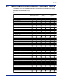
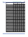
Valid/Invalid Communication Command Tables ......................................... 2-49
Revision Information
IM CW240C-E
1st Edition : Jun.30,2004
Blank Page
<Toc>
1-1
<Chapter 1. RS-232 Communication Function>
1.
RS-232 Communication Function
1.1
RS-232 Interface Specifications
Receiving Function
With this function, you can make settings via an RS-232 communication interface in basically the same way as you do with the panel keys.
Sending Function
With this function, you can output setup data, measured data, and error codes via the
RS-232 communication interface.
RS-232 Interface Specifications
Electrical and Mechanical characteristics: Conforms to EIA RS-232
Connection:
Point-to-point
Communication:
Full duplex
Synchronization:
Start-stop synchronization
Baud rate:
1200, 2400, 4800, 9600, 19200, and 38400 bps
Start bit:
1 bit (fixed)
Data length:
7 or 8 bits
Parity:
Even, odd, or none
Stop bit:
1 or 2 bits
Connector:
9-pin D-sub
Hardware handshake:
For CA (RTS) and CB (CTS) signals, a selection
can be made as to whether the signals are
always logically "true" or are used as control-line
signals.
Software handshake:
Flow control can be carried out using X-ON and
X-OFF codes.
X-ON: ASCII 11H
X-OFF: ASCII 13H
Receive buffer length:
2048 bytes
Send buffer length:
50k bytes
IM CW240C-E
1st Edition : Jun.30,2004
<Toc>
1.2
1-2
<Chapter 1. RS-232 Communication Function>
Connecting CW240 through RS-232 Interface
When connecting the CW240 to a computer, make sure the methods used for handshake,
data transmission rate, and data format are the same on both the CW240 and the computer.
For details, see the following pages. Also, be sure to use interface cables that match the
specifications of the CW240.
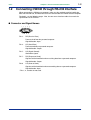
● Connector and Signal Names
1
2
6 7
Pin 2:
3
4
5
8 9
RD (Receive Data)
Data received from the personal computer.
Signal direction: Input
Pin 3:
SD (Send Data)
Data transmitted to a personal computer.
Signal direction: Output
Pin 5:
SG (Signal Ground)
Ground for signals.
Pin 7:
RS (Request to Send)
Signal used for handshake when receiving data from a personal computer.
Signal direction: Output
Pin 8:
CS (Clear to Send)
Signal used for handshake when transmitting data to a personal computer.
Signal direction: Input
* Pins 1, 4, 6 and 9 are not used.
IM CW240C-E
1st Edition : Jun.30,2004
<Toc>
<Chapter 1. RS-232 Communication Function>
1-3
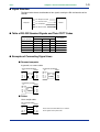
● Signal Direction
The figure below shows the directions of the signals used by the RS-232 interface of the
CW240.
Computer
RS: Request to Send
7
CS: Clear to Send
8
SD: Send Data
3
RD: Receive Data
2
CW240
● Table of RS-232 Standard Signals and Their CCITT Codes
Code
Pin No.
(9-pin connector)
RS-232
CCITT
JIS
5
AB (GND)
102
SG
Signal Ground
3
BA (TXD)
103
SD
Transmitted Data
2
BB (RXD)
104
RD
Received Data
7
CA (RTS)
105
RS
Request to Send
8
CB (CTS)
106
CS
Clear to Send
Description
● Examples of Connecting Signal Lines
■ Personal computer
In general, use a cross cable.
• OFF-OFF/XON-XON
PC
SD
RD
RS
CS
SG
3
2
7
8
5
• XON-RTS (XON-RS)
CW240
3
2
7
8
5
SD
RD
RS
CS
SG
PC
SD
RD
RS
CS
SG
3
2
7
8
5
CW240
3
2
7
8
5
SD
RD
RS
CS
SG
• CTS-RTS (CS-RS)
PC
SD
RD
RS
CS
SG
3
2
7
8
5
CW240
3
2
7
8
5
SD
RD
RS
CS
SG
■ Printer
Use a straight cable.
Use a straight cable.
Printer
SD
RD
3
2
RS 8
GND 5
CW240
3
2
SD
RD
8 CS
5 GND
Please refer to the IM CW240 user’s manual
for the signals on the printer side.
IM CW240C-E
1st Edition : Jun.30,2004
<Toc>
1.3
1-4
<Chapter 1. RS-232 Communication Function>
Handshake Methods
For the CW240 clamp-on power meter to be able to communicate with a personal computer
through the RS-232 interface, the equipment on both sides must agree on a set of rules
and go through a series of procedures relating to electrical signals to ensure reliable data
exchange. This series of procedures is called a handshake. Because there are many
handshake methods that can be used in combination with a computer. It is essential that
the same method is chosen for the meter and the computer.
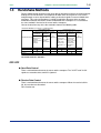
You can choose from any of the four methods shown in the following table.
Handshake Methods (䊊 means it is a valid selection)
Data Sending Control
(Control of sending data to a computer)
Software
Handshake
Handshake method Stops sending
when X-OFF is
received.
Resumes when
X-ON is
received.
Hardware
Handshake
Data Receiving Control
(Control of receiving data from a computer)
Software
Handshake
No
Stops sending
Sends X-OFF
handshake
when CB
when receive
(CTS) is false.
data buffer is 3/4
Resumes
full.
when it is true.
Sends X-ON
when receive
data buffer is 1/4
full.
Hardware
Handshake
No
Sets CA (RTS)
handshake
to False when
receive data
buffer is 3/4 full.
Sets to True
when receive
data buffer is
1/4 full.
OFF/OFF
XON/XON
XON/RS
CS/RS
The default method is "OFF/OFF."
OFF-OFF
● Send Data Control
There is no handshake between the meter and the computer. The "X-OFF" and "X-ON"
signals are treated as data, and CS is ignored.
● Receive Data Control
There is no handshake between the meter and the computer. When the receive buffer is
full, all extra data are discarded.
RS is fixed to true.
IM CW240C-E
1st Edition : Jun.30,2004
<Toc>
<Chapter 1. RS-232 Communication Function>
1-5
XON-XON
● Send Data Control
A software handshake is performed between the meter and the computer. If the "X-OFF"
code is received when data is being sent to the computer, the meter stops sending data.
When it receives the next "X-ON" code, it resumes data sending. The CS signal from the
computer is ignored.
● Receive Data Control
A software handshake is performed between the meter and the computer. When there is
512 bytes of free space in the receive buffer, the meter sends an "X-OFF" code. When the
free space is 1536 bytes, it sends an "X-ON" code.
RS is fixed to true.
XON-RS
● Send Data Control
A software handshake is performed between the meter and the computer. If the "X-OFF"
code is received when data is being sent to the computer, the meter stops sending data.
When it receives the next "X-ON" code, it resumes data sending. The CS signal from the
computer is ignored.
● Receive Data Control
A hardware handshake is performed between the meter and the computer. When there is
512 bytes of free space in the receive buffer, the meter sets "RS=False." When the free
space is 1536 bytes, it sets "RS=True".
CS-RS
● Send Data Control
A hardware handshake is performed between the meter and the computer. If CS becomes
False when data is being sent to the computer, the meter stops sending data. When CS
becomes True, it resumes data sending. The "X-ON" and "X-OFF" are treated as data.
● Receive Data Control
A hardware handshake is performed between the meter and the computer. When there is
512 bytes of free space in the receive buffer, the meter sets "RS=False." When the free
space is 1536 bytes, it sets "RS=True".
IM CW240C-E
1st Edition : Jun.30,2004
<Toc>
<Chapter 1. RS-232 Communication Function>
1-6
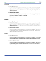
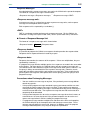
Precautions on Data Receive Control
When the CW240 power meter is controlling receive data by means of a handshake,
additional data may be sent from the computer even if there is less than 512 bytes of free
space in the receive buffer. If the receive buffer becomes full, all extra data are discarded
regardless of the handshake. When the receive buffer recovers free space, it resumes
data storing.
2048 bytes
Used
Used
512 bytes of
free space
1536 bytes of free space
In communication based on
handshaking, the meter stops receiving
data if it cannot transfer data internally
fast enough and the buffer's free space
becomes less than 512 bytes.
If the free space increases to 1536
bytes as a result of continuing internal
data transfer, the meter resumes data
receiving.
Regardless of the handshake, all extra
data will be discarded if the buffer
becomes full.
Used
Data Receive Control Using Handshaking
TIP
The program on the personal computer must be designed so that the receive buffers on the meter and
the personal computer do not become full.
IM CW240C-E
1st Edition : Jun.30,2004
<Toc>
1.4
1-7
<Chapter 1. RS-232 Communication Function>
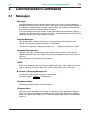
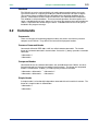
Matching the Data Format
The CW240 uses start-stop synchronization to communicate through its RS-232 interface.
In communication based on start-stop synchronization, a start bit is added every time a
character is transmitted, where the start bit is followed by data, parity, and stop bits (see the
figure below).
Idle state of circuit
Return of circuit to idle
state (dotted line), or
detection of the next data's
start bit (solid line)
One character
Data bits
(7 or 8 bits)
Stop bit
Start bit
Parity bit
(Even, odd, or none)
1
(1 or 2 bits)
2
IM CW240C-E
1st Edition : Jun.30,2004
Blank Page
<Chapter 2. Communication Commands>
<Toc>
2.
Communication Commands
2.1
Messages
2-1
Messages
Communication between the CW240 clamp-on power meter and a personal computer is
carried out in blocks of data called messages. Messages sent by the personal computer to
the CW240 are called program messages, and messages received by the personal computer from the CW240 are called response messages.
If a received program message contains a query command (a command which requests a
response), the CW240 returns a response message. A single response message is always
returned in response to a single program message.
Program Messages
As explained above, program messages are sent from the personal computer to the
CW240. The format of a program message is shown below.
<Program message unit>;<Program message unit>; ... <Program message unit><PMT>
<Program message unit>
A program message is a train of one or more program message units; each unit corresponds to one command. The CW240 executes the commands in the order that they are
received.
Each program unit is separated by a semicolon (;).
<PMT>
PMT is a terminator used to terminate each program message. For the CW240, the terminator is a string of CR (ASCII-code “0DH”) and LF (ASCII-code “0AH”) characters.
● Format of Program Message Unit
The format of a program message unit is shown below.
<Program header>
Space
<Program data>
<Program header>
The program header contains the command type.
<Program data>
If there are certain conditions for executing a command, they are appended as program
data. The program data follows the program header and is separated from the program
header by a space (ASCII-code “20H”). If there are multiple data, they are separated by a
comma (,).
IM CW240C-E
1st Edition : Jun.30,2004
2-2
<Chapter 2. Communication Commands>
<Toc>
Response Messages
As explained earlier, response messages are sent by the CW240 to the personal computer.
The format of a response message is shown below.
<Response message>;<Response message>; ... <Response message><RMT>
<Response message unit>
A response message is a train of one or more response message units; each response
message unit corresponds to one response.
Each response unit is separated by a semicolon (;).
<RMT>
RMT is a terminator used to terminate each response message. For the CW240, the
terminator is a string of CR (ASCII-code “0DH”) and LF (ASCII-code “0AH”) characters.
● Format of Response Message Unit
The format of a response message unit is shown below.
<Response header>
Space
<Response data>
<Response header>
It is possible to program the CW240 so a response header precedes the response data.
Response data is separated from the header by a space.
<Response data>
Response data contains the contents of the response. If there are multiple data, they are
separated by a comma (,).
If a program message contains multiple queries, the responses are made in the same order
as the queries. For most queries, the CW240 returns only one response message unit.
The CW240 returns more than one response message unit to some queries, however. The
first query is always answered with the first response message unit. However, the nth
query does not always agree with the nth response message unit. To be certain that the
given response message unit corresponds to the correct query, place one query in each
program message.
Precautions when Exchanging Messages
• You can send the next message at any time, if the previously sent message did not
contain any queries.
• If the previous program message contained a query, you cannot send the next message until the entire response message is received. If you send the next program
message before any response message is received or after only part of a message is
received, an error will occur. The response message that was not received at all or
completely will be discarded.
• If the personal computer tries to receive a response message when there is none, an
error will occur. An error also occurs if the personal computer tries to receive a response message before it finishes sending the program message.
• If a program message contains multiple units and some of the units are incomplete,
the CW240 will pick up the incomplete units and attempt to execute them. These
attempts may not always be successful, however. In addition, even if the program
message contained queries, they may not always be responded to.
IM CW240C-E
1st Edition : Jun.30,2004
2-3
<Chapter 2. Communication Commands>
<Toc>
Deadlock
The CW240 has receive and send buffers for storing program and response messages.
The receive buffer has a capacity of 2048 bytes and the send buffer can store 50 kbytes.
(The number of bytes available will vary depending on the operating conditions of the
CW240.) If both buffers become full at the same time, the CW240 becomes inoperative.
This condition is called a deadlock. To resume normal operation, discard response messages. A deadlock will not occur, however, if the size of the program message including the
<PMT> is kept below the number of bytes above. A deadlock never occurs if no query is
included in the program message.
2.2
Commands
Commands
There are two types of command (program header) that can be sent from the personal
computer to the CW240. They differ in the format of their program headers.
Common Command Header
Commands defined in IEEE 488.2-1987 are called common commands. The header
format of a common command is shown below. An asterisk (*) always precedes a common
command.
*<Mnemonic>?
*<Mnemonic>
Compound Header
Commands other than common commands, that are dedicated to the CW240, are classified and arranged in a hierarchy according to their functions. The format of a compound
header is shown below. A colon (:) is used to specify a lower-level header.
*<Mnemonic>:<Mnemonic> ... :<Mnemonic>?
*<Mnemonic>:<Mnemonic> ... :<Mnemonic>
Simple Header
A simple header is a functionally independent command with no hierarchical structure. The
format of a simple header is shown below.
*<Mnemonic>?
*<Mnemonic>
IM CW240C-E
1st Edition : Jun.30,2004
2-4
<Chapter 2. Communication Commands>
<Toc>
When Concatenating Commands
• Command Group
A group of commands which share the same compound header is called a command
group. A command group may contain sub-groups.
Example
:STARt:EXECute
:STARt:METHod
:STARt:TIME
• When Concatenating Commands of the Same Group
The CW240 stores information on which hierarchical level the command currently
being executed belongs to, and performs analysis on the assumption that the next
command will also belong to the same level. Therefore, you may omit the header of
the next command if the two commands belong to the same group.
Example
:STARt:METHod TIME; TIME 2003,8,12,18,21<PMT>
• When Concatenating Commands of Different Groups
Include a colon (:) before the header, if the following command does not belong to the
same group as the preceding command.
Example
:STARt:METHod TIME;:STOP:METHod
TIME<PMT>
• When Concatenating Common Commands
Common commands defined in IEEE 488.2-1987 are independent of hierarchy.
A colon (:) is not necessary before a common command.
Example
:STARt:METHod TIME;*CLS;TIME 2003,8,12,18,21<PMT>
• When Separating Commands with <PMT>
If a terminator is used to separate two commands, each command is a separate
message. Specify the command header for each command even when the commands from the same command group are being concatenated.
Rules of Header Interpretation
The CW240 interprets a received header according to the following rules.
• Mnemonics are not case-sensitive.
Example: SYSTem can also be written as system or System.
• The lower-case portion of a header can be omitted.
Example: SYSTem can also be written as SYSTE or SYST.
• The question mark (?) at the end of the header denotes a query. You cannot omit the
question mark.
Example: SYSTem? cannot be abbreviated to anything shorter than SYST?.
IM CW240C-E
1st Edition : Jun.30,2004
<Chapter 2. Communication Commands>
<Toc>
2.3
2-5
Response
Upon receiving a query from the personal computer, the CW240 returns a response message to the computer. A response message is sent in either of the following forms.
• Response consisting of a header and data
If the response can be used directly as a program message, the response message
will include the command header.
• Response consisting of data only
If the response cannot be used directly as a program message (i.e., the response is a
query-only command), the response message will include only the data. However,
some query-only commands will include a header.
● When you want a response without a header
You can have the header removed from a response that has a header and data by using
the COMMunicate:HEADer command.
IM CW240C-E
1st Edition : Jun.30,2004
2.4
2-6
<Chapter 2. Communication Commands>
<Toc>
Data
Data
The data section comes after the header. A space must be included between the header
and the data. The data contains conditions and values. It is classified as follows.
Data
Description
<Numeric>
Numerical value
<Decimal>
Value expressed as a decimal number
<Voltage>, <Current>, <Frequency>
Value with a physical dimension
<Character data>
Specified character string (mnemonic).
<Boolean>
Indicates ON/OFF. Specify with [ON], [OFF], or a value.
<Character string data>
Arbitrary character string
<Decimal>
<Decimal> indicates a value expressed as a decimal number, as shown in the table below.
Decimal values are given in the NR form specified in ANSI X3.42-1975.
Symbol
Description
Example
<NR1>
Integer
125 -1 +1000
<NR2>
Fixed-point number
125.0 -.90 +00.1
<NR3>
Floating-point number
125.0E+0 -9E-1 +.1E4
<NRf>
Any of the forms <NR1> to <NR3> is allowed.
• <NRf> represents the case when any of the forms <NR1> to <NR3> can be used.
The CW240 accepts decimal values from the personal computer in any form.
• The form, among <NR1> to <NR3>, used for the response message is predetermined
for each query. The same form is used irrespective of whether the value is large or
small.
• When using <NR3>, the “+” after the “E” can be omitted, but the “–” cannot.
• If a value outside the setting range is specified, the closest valid value will be used.
• If the value specified is beyond the precision of the CW240, the value will be rounded.
<Voltage>, <Time>, <Frequency>
<Voltage>, <Time> and <Frequency> indicate decimal values which have a physical
dimension. <Multiplier> or <Unit> can be attached to the <NRf> form. The values are
specified in any of the following forms.
Form
Example
<NRf><Multiplier><Unit>
5MV
<NRf><Unit>
<NRf><Multiplier>
<NRf>
5E-3V
5M
5E-3
IM CW240C-E
1st Edition : Jun.30,2004
<Chapter 2. Communication Commands>
<Toc>
2-7
<Multiplier>
The following multipliers are available.
Symbol
Word
Description
EX
Exa
1018
PE
Peta
1015
T
Tera
1012
G
Giga
109
MA
Mega
106
K
Kilo
103
M
Mili
10-3
U
Micro
10-6
N
Nano
10-9
P
Pico
10-12
F
Femto
10-15
<Unit>
The following units are available.
Symbol
Word
Description
V
Volt
Voltage
A
Ampere
Current
HZ
Hertz
Frequency
KHZ
Kilohertz
Frequency
• <Multiplier> and <Unit> are not case-sensitive.
• “U” is used to indicate “µ”.
• “MA” is used for Mega (M) to distinguish it from Mili. If used for current, however, “MA”
is interpreted as Milliampere. To refer to Megaampere, write as “MAA”.
• If both <Multiplier> and <Unit> are omitted, the default unit (V, A or Hz) will be used.
• Response messages are always expressed in the <NR3> form. The default unit is
used without the <Multiplier> or the <Unit>.
<Character Data>
<Character data> is a data of specific characters (mnemonic). It is mainly used to indicate
options and is chosen from character strings given in { }. For interpretation rules, see
“Rules of Header Interpretation.”
Form
Example
{U1 | U2 | U3}
U1
IM CW240C-E
1st Edition : Jun.30,2004
2-8
<Chapter 2. Communication Commands>
<Toc>
<Boolean>
<Boolean> is a type of data that indicates ON or OFF, and is expressed in one of the
following forms.
Form
Example
{ON|OFF|<NRF>}
ON OFF 1 0
• When expressing <Boolean> in <NRf> form, OFF is selected if the rounded integer
value is “0” and ON is selected if the rounded integer is “non 0.”
• A response message is always “1” if the value is ON and “0” if it is OFF.
<Character String Data>
<Character string data> is an arbitrary character string unlike the <character data>, which
uses only specific characters. The character string must be enclosed in single quotation
marks (‘) or double quotation marks (“).
Form
Example
<Character string data>
'ABC' "IEE488.2-1987"
• If a character string contains a double quotation mark (“), use two double quotation
marks (“ “) to indicate it. This rule also applies to a single quotation mark (‘) within a
character string.
• Response messages always use double quotation marks (“) around the character
string.
• Since <Character string data> is an arbitrary character string, leaving the end single
quotation mark (‘) or double quotation mark (“) will cause the CW240 to interpret the
program message unit as part of the <character string data>. As a result, errors may
not be detected properly.
<Filename>
<Filename> is data that denotes a file name. It is expressed in one of the following forms.
Form
Example
{ <NRf>|<Character data>|<Character string data>}
1 CASE "CASE"
• In the <NRf> form, a file name is an ASCIII code obtained by rounding an 8-digit
value into an integer (for example, “1” denotes “00000001.”). A negative value is not
allowed, however.
• In the <character data> or <character string data> form, a file name is the first eight
characters.
• A response message is always returned in the <character string data> form.
IM CW240C-E
1st Edition : Jun.30,2004
2.5
2-9
<Chapter 2. Communication Commands>
<Toc>
Output Queue and Error Queue
● Output Queue
The output queue is provided to store response messages to queries. For example, when
the :MEASure:VALUe? query is sent to request output of measured data, the response
data will be stored in the output queue until it is read out.
Data items are stored in sequence in the output queue and then read out on a first-in-firstout basis. The output queue is emptied in any of the following cases, in addition to a case
when it is entirely read out.
• A new message is received from the personal computer.
• A deadlock occurs.
• The power is turned on again.
● Error Queue
The error queue stores the error number when an error occurs. For example, if the personal computer sends an illegal program message, the error queue stores error number
102.
The contents of the error queue can be read using the STATus:ERRor? query. As with the
output queue, messages in the error queue are read out on a first-in-first-out basis.
If the error queue overflows, the last error queue is replaced with error number 350.
The error queue is emptied in either of the following cases, in addition to a case when it is
entirely read out).
• The *CLS command is received.
• The power is turned on again.
Error Code
(Error No.)
Contents
Description and Corrective Measures
102
Syntax Error
Syntax error other than the ones listed below
200
Execution Error
Cannot execute the command
350
Queue Overflow
Read the error queue
Query DEADLOCKED
Limit the length of the program message including
the<PMT>to the following buffer lengths or less:
Receive buffer length:
2048 bytes
Send buffer length:
50k bytes
430
IM CW240C-E
1st Edition : Jun.30,2004
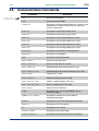
2.6
Communication Commands
Command
Click each command
for detailed descriptions
2-10
<Chapter 2. Communication Commands>
<Toc>
Description
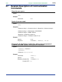
*CLS
Clears the error queue
*IDN?
Queries the meter model
:1PCOnnect
Sets/queries the destination to which the 1-phase 3-wire
component of a 3-phase 3-wire and 1-phase 3-wire
system is connected
:AINP:CH1
Sets/queries the A/D-input range (CH1)
:AINP:CH2
Sets/queries the A/D-input range (CH2)
:AOUT:CH1
Sets/queries the D/A-output data items (CH1)
:AOUT:CH2
Sets/queries the D/A-output data items (CH2)
:AOUT:CH3
Sets/queries the D/A-output data items (CH3)
:AOUT:CH4
Sets/queries the D/A-output data items (CH4)
:AVERaging
Sets/queries the number of averaging times
:BACKlight
Sets/queries the backlight
:BEEP
Sets/queries the beep function
:CARD:DELEte
Deletes the file of PC card
:CARD:DIREctory?
Queries the file name of PC card
:CARD:DOWNload
Download from internal memory to PC card
:CARD:DOWNload:ALL
Download all the file of internal memory to PC card
:CARD:FORMat
Formats the PC card
:CARD:PICKout?
Transfers the file from the PC card
:CARD:SETTing:LOAD
Loads a setting file from the PC card
:CARD:SETTing:SAVE
Saves a setting file to the PC card
:CARD:STATe?
Queries the PC card status
:CLAMp
Sets/queries the type of clamp(Model name of
Clamp-on Probe)
:COMMunicate:HEADer
Sets/queries whether or not the header of
communication-output
:CONNect
Sets/queries the RS-232 connection destination
:CONTrast
Sets/queries the LCD contrast
:CT
Sets/queries the CT ratio
:CURRent:RANGe
Sets/queries the current range
:DISPlay:MEASure
Sets/queries measurement data items of display
IM CW240C-E
1st Edition : Jun.30,2004
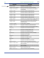
Command
Click each command
for detailed descriptions
2-11
<Chapter 2. Communication Commands>
<Toc>
Description
:DISPlay:MODE
Sets/queries the mode of display
:DOUTput:COPY:DATAout
Saves on-screen data (as with the COPY key)
:DOUTput:COPY:MEDIa
Sets/queries the saving and printing destination for
on-screen data
:DOUTput:ITEM1
Sets/queries group 1 of output data items
:DOUTput:ITEM2
Sets/queries group 2 of output data items
:DOUTput:ITEM3
Sets/queries group 3 of output data items
:DOUTput:ITEM4
Sets/queries group 4 of output data items
:DOUTput:ITEM5
Sets/queries group 5 of output data items
:DOUTput:MEDIa
Sets/queries the saving destination for output data items
:DOUTput:SAVE
Saves measurement data (as with the SAVE key)
:DOUTput:WAVE
Sets/queries the state of the saving function for
waveform data files
:FILEname:CHANge
Changes/queries a filename
:FILEname:MEASure
Sets/queries a filename of measurement date
:FILTer
Sets/queries the low-pass filter for frequency source
:FREQuency
Sets/queries the measurement frequency
:HOLD
Sets/queries the display holding status
:HPA
Sets/queries the calcutational method
:HYSTeresis
Sets/queries the hysteresis factor in percentage
:ID
Sets/queries the ID number
:INTErval
Sets/queries the interval
:KLOCk
Sets/queries the keylock function
:LANGuage
Sets/queries the language
:LOAD
Sets/queries the number of system loads
:MEASure:STATe?
Queries the state of integration measurement
:MEASure:TIME:START?
Queries the date and time of the actual start of integration measurement
:MEASure:TIME:STOP?
Queries the date and time of the actual stop of integration measurement
:MEASure:VALUe?
Queries measurement values
:MEMOry:DIREctory?
Queries the file name of internal memory
IM CW240C-E
1st Edition : Jun.30,2004
Command
Click each command
for detailed descriptions
2-12
<Chapter 2. Communication Commands>
<Toc>
Description
:MEMOry:FORMat
Formats data files on internal memory
:MEMOry:PICKout?
Transfers the file from internal memory
:MEMOry:SETTing:DELEte
Deletes a setting file from internal memory
:MEMOry:SETTing:FORMat
Formats setting files on internal memory
:MEMOry:SETTing:LOAD
Loads a setting file from internal memory
:MEMOry:SETTing:SAVE
Saves a setting file to internal memory
:OPERationvar
Sets/queries whether the reactive power method is set
to ON or OFF
:ORDEr
Sets/queries the order of harmonics’ bar graphs to
display
:RESEt
Resets the system
:SAMPling
Sets/queries the sampling method
:SOURce
Sets/queries the frequency source
:STARt:EXECute
Starts integration measurement
:STARt:METHod
Sets/queries the starting method of integration
measurement
:STARt:TIME
Sets/queries the date and time of the start of integration
measurement
:STATus:ERRor?
Queries the error codes that occurred
:STDVoltage
Sets/queries the reference (standard) voltage
:STOP:EXECute
Stops integration measurement forcibly
:STOP:METHod
Sets/queries the stopping method of integration
measurement
:STOP:TIME
Sets/queries the date and time of the stop of integration
measurement
:SYSTem:DATE
Sets/queries the date
:SYSTem:TIME
Sets/queries the time
:THD
Sets/queries the method of Total Harmonic Distortion
:THREshold:DIP
Sets/queries the threshold value of voltage dips
:THREshold:INTErruption
Sets/queries the threshold value of momentary voltage
interruptions
:THREshold:SWELl
Sets/queries the threshold value of voltage swells
:TIMEr
Sets/queries the end-of- measurement timer setting
:VDETect:MEASure
Sets/queries whether or not to detect voltage fluctuation
(voltage quality)
IM CW240C-E
1st Edition : Jun.30,2004
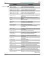
Command
Click each command
for detailed descriptions
2-13
<Chapter 2. Communication Commands>
<Toc>
Description
:VDETect:VALUe?
Queries detected voltage fluctuation (voltagequality)
values
:VOLT:RANGe
Sets/queries the voltage range
:VT
Sets/queries the VT ratio
:WH:CLEAr
Executes clearing of integrated values to zero
:WH:INTErval:DIGIt
Sets/queries the position of the decimal point of electric
energy (Interval of Demand measure mode)
:WH:INTErval:UNIT
Sets/queries the unit of electric energy (Interval of
Demand measure mode)
:WH:TOTAl:DIGIt
Sets/queries the position of the decimal point of electric
energy
:WH:TOTAl:UNIT
Sets/queries the unit of electric energy
:WIRIng
Sets/queries the wiring type
IM CW240C-E
1st Edition : Jun.30,2004
<Toc>
<Chapter 2. Communication Commands>
2.7
Detailed Description of Communication
Commands
2-14
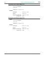
Clears the error queue
Syntax
*CLS
Example
Commands
*CLS
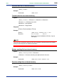
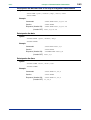
Queries the meter model
Syntax
*IDN?
Response
<Character string 1>,<Character string 2>,<Numeric3>,<Character string 4>
<Character string 1> = Manufacturer "YOKOGAWA"
<Character string 2> = Model "CW240"
<Numeric3> = Serial No. 0 (always 0)
<Character string 4> = Firmware version "F1.00"
Example
Queries
*IDN?
Response
"YOKOGAWA", "CW240",0, "F1.00"
Sets/queries the destination to which the 1-phase 3-wire component of
a 3-phase 3-wire and 1-phase 3-wire system is connected
Syntax
:1PCOnnect <Character>
:1PConnect?
<Character> = {R-S|S-T|T-R}
Example
Commands
:1PCO R-S
Queries
:1PCO?
Response (Header ON)
:1PCONNECT R-S
(Header OFF) R-S
IM CW240C-E
1st Edition : Jun.30,2004
<Chapter 2. Communication Commands>
<Toc>
2-15
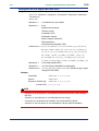
Sets/queries the A/D-input range (CH1)
Syntax
:AINP:CH1 <Character>
:AINP:CH1?
<Character> = {100MV|1V|5V}
Example
Commands
:AINP:CH1 100MV
Queries
:AINP:CH1?
Response (Header ON)
:AINP:CH1 100MV
(Header OFF) 100MV
Sets/queries the A/D-input range (CH2)
Syntax
:AINP:CH2 <Character>
:AINP:CH2?
<Character> = {100MV|1V|5V}
Example
Commands
:AINP:CH2 100MV
Queries
:AINP:CH2?
Response (Header ON)
:AINP:CH2 100MV
(Header OFF) 100MV
IM CW240C-E
1st Edition : Jun.30,2004
2-16
<Chapter 2. Communication Commands>
<Toc>
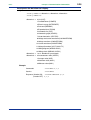
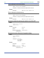
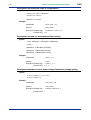
Sets/queries the D/A-output data items (CH1)
Syntax
:AOUT:CH1 <Numeric1>,<Numeric2>,<Character3>,<Numeric4>,<Numeric5>,
<Character 6>
:AOUT:CH1?
<Numeric1> =
1 to 4:Number of system loads
<Numeric2> =
0 to 6
0:Normal measurement
1:Electric energy
2:Harmonics level
3:Harmonics content
4:Phase angle of harmonics
5:Total harmonics
6:Total harmonic distortion (THD)
<Character 3> = {U1|U2|U3|UAVE|I1|I2|I3|I4|IAVE|P|Q|S|PF|PA|F|
WH+|WH-|VARH+|VARH-|U1_3P|U2_3P|U3_3P|UAVE_3P|
I1_3P|I2_3P|I3_3P|IAVE_3P|P_3P|Q_3P|S_3P|PF_3P|
PA_3P|WH+_3P|WH-_3P|VARH+_3P|VARH-_3P|U1_1P|
U2_1P|UAVE_1P|I1_1P|I2_1P|IAVE_1P|P_1P|Q_1P|
S_1P|PF_1P|PA_1P|WH+_1P|WH-_1P|VARH+_1P|VARH-_1P}
<Numeric4> =
1 to 50:Output order(ORD.)
<Numeric5> =
1/10/100:Output scaling(MAG.:magnification)
<Character 6> = {1K|5K|10K|50K|100K|500K|1MA}:Electric energy’s output
rating(OUTPUT RATE)
Example
Commands
:AOUT:CH1 1,0,P,1,1,1K
Queries
:AOUT:CH1?
Response (Header ON)
:AOUT:CH1 1,0,P,1,1,1K
(Header OFF) 1,0,P,1,1,1K
NOTE
• <Numeric 4> to<Character 6> are omitted for normal measurement, total harmonics,
and THD.
• <Numeric 4> and <Numeric 5> are omitted for electric energy.
• <Character 6> is omitted for the harmonics level and harmonics content.
• <Numeric 5> and <Character 6> are omitted for the phase angle of harmonics.
IM CW240C-E
1st Edition : Jun.30,2004
2-17
<Chapter 2. Communication Commands>
<Toc>
Sets/queries the D/A-output data items (CH2)
Syntax
:AOUT:CH2 <Numeric1>,<Numeric2>,<Character3>,<Numeric4>,<Numeric5>,
<Character 6>
:AOUT:CH2?
<Numeric1> =
1 to 4:Number of system loads
<Numeric2> =
0 to 6
0:Normal measurement
1:Electric energy
2:Harmonics level
3:Harmonics content
4:Phase angle of harmonics
5:Total harmonics
6:Total harmonic distortion
<Character 3> = {U1|U2|U3|UAVE|I1|I2|I3|I4|IAVE|P|Q|S|PF|PA|F|
WH+|WH-|VARH+|VARH-|U1_3P|U2_3P|U3_3P|UAVE_3P|
I1_3P|I2_3P|I3_3P|IAVE_3P|P_3P|Q_3P|S_3P|PF_3P|
PA_3P|WH+_3P|WH-_3P|VARH+_3P|VARH-_3P|U1_1P|
U2_1P|UAVE_1P|I1_1P|I2_1P|IAVE_1P|P_1P|Q_1P|
S_1P|PF_1P|PA_1P|WH+_1P|WH-_1P|VARH+_1P|VARH-_1P}
<Numeric4> =
1 to 50:Output order(ORD.)
<Numeric5> =
1/10/100:Output scaling(MAG.:magnification)
<Character 6> = {1K|5K|10K|50K|100K|500K|1MA}:Electric energy’s output
rating(OUTPUT RATE)
Example
Commands
:AOUT:CH2 1,0,Q,1,1,1K
Queries
:AOUT:CH2?
Response (Header ON)
:AOUT:CH2 1,0,Q,1,1,1K
(Header OFF) 1,0,Q,1,1,1K
NOTE
• <Numeric 4> to<Character 6> are omitted for normal measurement, total harmonics,
and THD.
• <Numeric 4> and <Numeric 5> are omitted for electric energy.
• <Character 6> is omitted for the harmonics level and harmonics content.
• <Numeric 5> and <Character 6> are omitted for the phase angle of harmonics.
IM CW240C-E
1st Edition : Jun.30,2004
2-18
<Chapter 2. Communication Commands>
<Toc>
Sets/queries the D/A-output data items (CH3)
Syntax
:AOUT:CH3 <Numeric1>,<Numeric2>,<Character3>,<Numeric4>,<Numeric5>,
<Character 6>
:AOUT:CH3?
<Numeric1> =
1 to 4:Number of system loads
<Numeric2> =
0 to 6
0:Normal measurement
1:Electric energy
2:Harmonics level
3:Harmonics content
4:Phase angle of harmonics
5:Total harmonics
6:Total harmonic distortion
<Character 3> = {U1|U2|U3|UAVE|I1|I2|I3|I4|IAVE|P|Q|S|PF|PA|F|
WH+|WH-|VARH+|VARH-|U1_3P|U2_3P|U3_3P|UAVE_3P|
I1_3P|I2_3P|I3_3P|IAVE_3P|P_3P|Q_3P|S_3P|PF_3P|
PA_3P|WH+_3P|WH-_3P|VARH+_3P|VARH-_3P|U1_1P|
U2_1P|UAVE_1P|I1_1P|I2_1P|IAVE_1P|P_1P|Q_1P|
S_1P|PF_1P|PA_1P|WH+_1P|WH-_1P|VARH+_1P|VARH-_1P}
<Numeric4> =
1 to 50:Output order(ORD.)
<Numeric5> =
1/10/100:Output scaling(MAG.:magnification)
<Character 6> = {1K|5K|10K|50K|100K|500K|1MA}:Electric energy’s output
rating(OUTPUT RATE)
Example
Commands
:AOUT:CH3 1,0,S,1,1,1K
Queries
:AOUT:CH3?
Response (Header ON)
:AOUT:CH3 1,0,S,1,1,1K
(Header OFF) 1,0,S,1,1,1K
NOTE
• <Numeric 4> to <Character 6> are omitted for normal measurement, total harmonics,
and THD.
• <Numeric 4> and <Numeric 5> are omitted for electric energy.
• <Character 6> is omitted for the harmonics level and harmonics content.
• <Numeric 5> and <Character 6> are omitted for the phase angle of harmonics.
IM CW240C-E
1st Edition : Jun.30,2004
2-19
<Chapter 2. Communication Commands>
<Toc>
Sets/queries the D/A-output data items (CH4)
Syntax
:AOUT:CH4 <Numeric1>,<Numeric2>,<Character3>,<Numeric4>,<Numeric5>,
<Character 6>
:AOUT:CH4?
<Numeric1> =
1 to 4:Number of system loads
<Numeric2> =
0 to 6
0:Normal measurement
1:Electric energy
2:Harmonics level
3:Harmonics content
4:Phase angle of harmonics
5:Total harmonics
6:Total harmonic distortion
<Character 3> = {U1|U2|U3|UAVE|I1|I2|I3|I4|IAVE|P|Q|S|PF|PA|F|
WH+|WH-|VARH+|VARH-|U1_3P|U2_3P|U3_3P|UAVE_3P|
I1_3P|I2_3P|I3_3P|IAVE_3P|P_3P|Q_3P|S_3P|PF_3P|
PA_3P|WH+_3P|WH-_3P|VARH+_3P|VARH-_3P|U1_1P|
U2_1P|UAVE_1P|I1_1P|I2_1P|IAVE_1P|P_1P|Q_1P|
S_1P|PF_1P|PA_1P|WH+_1P|WH-_1P|VARH+_1P|VARH-_1P}
<Numeric4> =
1 to 50:Output order(ORD.)
<Numeric5> =
1/10/100:Output scaling(MAG.:magnification)
<Character 6> = {1K|5K|10K|50K|100K|500K|1MA}:Electric energy’s output
rating(OUTPUT RATE)
Example
Commands
:AOUT:CH4 1,0,F,1,1,1K
Queries
:AOUT:CH4?
Response (Header ON)
:AOUT:CH4 1,0,F,1,1,1K
(Header OFF) 1,0,F,1,1,1K
NOTE
• <Numeric 4> to <Character 6> are omitted for normal measurement, total harmonics,
and THD.
• <Numeric 4> and <Numeric 5> are omitted for electric energy.
• <Character 6> is omitted for the harmonics level and harmonics content.
• <Numeric 5> and <Character 6> are omitted for the phase angle of harmonics.
IM CW240C-E
1st Edition : Jun.30,2004
2-20
<Chapter 2. Communication Commands>
<Toc>
Sets/queries the number of averaging cycles for on-screen readings
Syntax
:AVERaging <Numeric>
:AVERaging?
<Numeric> = 1/2/5/10/20
Example
Commands
:AVER 5
Queries
:AVER?
Response (Header ON)
:AVERAGING 5
(Header OFF) 5
Sets/queries the backlight
Syntax
:BACKlight <Boolean>
:BACKlight?
Example
Commands
:BACK ON
Queries
:BACK?
Response (Header ON)
:BACKLIGHT 1
(Header OFF) 1
Sets/queries the beep function
Syntax
:BEEP <Boolean>
:BEEP?
Example
Commands
:BEEP ON
Queries
:BEEP?
Response (Header ON)
:BEEP 1
(Header OFF) 1
Deletes the file of PC card
Syntax
:CARD:DELEte <Filename>
Example
Commands
:CARD:DELE 240AM000.CSV
IM CW240C-E
1st Edition : Jun.30,2004
<Chapter 2. Communication Commands>
<Toc>
2-21
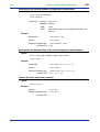
Queries the file name of PC card
Syntax
:CARD:DIREctory? <Character>
<Character>= {MEAS|INST|WAVE|SET|ALM|BMP}
MEAS: Measurement file
INST:
Short interval file
WAVE: Waveform file
SET:
Setting file
ALM:
Detected voltage fluctuation file
(Voltage quaity)
BMP:
Screen file
(Hard copy)
Response
<Filename>,<Size>,...
Example
Queries
:CARD:DIRE? MEAS
Response
240AM000,1024
Downloads from internal memory to PC card
Syntax
:CARD:DOWNload <Filename 1>,<Filename 2>
<Filename 1> = Filename of internal memory
<Filename 2> = Filename to save of the PC card
Example
Commands
:CARD:DOWN 240AM000.CSV, 240AM999.CSV
Downloads all the files of internal memory to PC card
Syntax
:CARD:DOWNload:ALL
Example
Commands
:CARD:DOWN:ALL
Formats the PC card
Syntax
:CARD:FORMat
Example
Commands
:CARD:FORM
IM CW240C-E
1st Edition : Jun.30,2004
2-22
<Chapter 2. Communication Commands>
<Toc>
Transfers the file from the PC card
Syntax
:CARD:PICKout? <Filename 1>,<Numeric2>,<Numeric3>
<Filename 1> = Filename to transfer
<Numeric2> = Start point.
<Numeric3> = Stop point.
Response
STX(02)+Transfers the data+ETX(03)
Example
Queries
:CARD:PICK? 240AM000.CSV,1,1000
Response
STX(02)CW240,.....ETX(03)
Returns the data of 240AM000.CSV file (1 byte to
1000 bytes)
NOTE
To execute this command, specify the RS-232 handshake settings between the CW240
and a personal computer to "CS/RS" beforehand.
Loads a setting file from the PC card
Syntax
:CARD:SETTing:LOAD <Character>
<Character> = Character data of up to 8 alphanumeric character
Example
Commands
:CARD:SETT:LOAD 240MC000
Saves a setting file to the PC card
Syntax
:CARD:SETTing:SAVE <Character>
<Character> = Character data of up to 8 alphanumeric character
Example
Commands
:CARD:SETT:SAVE 240MC000
IM CW240C-E
1st Edition : Jun.30,2004
2-23
<Chapter 2. Communication Commands>
<Toc>
Queries the PC card status
Syntax
:CARD:STATe?
Response
1:The PC card is set.
0: The PC card is not set.
Example
Queries
:CARD:STAT?
Response (Header ON)
:CARD:STATE 1
(Header OFF) 1
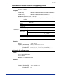
Sets/queries the type of clamp (Model name of Clamp-on Probe)
Syntax
:CLAMp <Numeric1>,<Character 2>
:CLAMp?
Response (Header ON)
:CLAM <Character 3>,<Character 4>,
<Character 5>,<Character 6>
(Header OFF) <Character 3>,<Character 4>,<Character 5>,
<Character 6>
<Numeric1> = 1 to 4 : Number of system loads
<Character 3> to <Character 6> = {96036|96033|96030|96031|96032|
96034_1|96034_2|96034_3|96035_1|96035_2}
Example
Commands
:CLAM 1,96033
Queries
:CLAM?
Response (Header ON)
:CLAMP 96033,96030,96031,96032
(Header OFF) 96033,96030,96031,96032
Sets/queries whether or not the header of communication-output
Syntax
:COMMunicate:HEADer <Boolean>
:COMMunicate:HEADer?
Example
Commands
:COMM:HEAD ON
Queries
:COMM:HEAD?
Response (Header ON)
:COMMUNICATE:HEADER 1
(Header OFF) 1
IM CW240C-E
1st Edition : Jun.30,2004
2-24
<Chapter 2. Communication Commands>
<Toc>
Sets/queries the RS-232 connection destination
Syntax
:CONNect <Character>
:CONNect?
<Character> = {PC|PRINTER}
Example
Commands
:CONN PC
Queries
:CONN?
Response (Header ON)
:CONNECT PC
(Header OFF) PC
Sets/queries the LCD contrast
Syntax
:CONTrast <Numeric>
:CONTrast?
<Numeric> = 1 to 8
Example
Commands
:CONT 4
Queries
:CONT?
Response (Header ON)
:CONTRAST 4
(Header OFF) 4
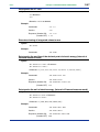
Sets/queries the CT ratio
Syntax
:CT <Numeric1>,<Numeric2>
:CT?
Response (Header ON)
:CT <Numeric3>,<Numeric4>,<Numeric5>,
<Numeric6>
(Header OFF) <Numeric3>,<Numeric4>,<Numeric5>,<Numeric6>
<Numeric1> = 1 to 4 : Number of system loads
<Numeric2> = 0.01 to 9999.99 : CT ratio
<Numeric3> = CT ratio of 1-system load
<Numeric4> = CT ratio of 2-system load
<Numeric5> = CT ratio of 3-system load
<Numeric6> = CT ratio of 4-system load
Example
Commands
:CT 1,2.0
Queries
:CT?
Response (Header ON)
:CT 2.00,3.00,4.00,5.00
(Header OFF) 2.00,3.00,4.00,5.00
IM CW240C-E
1st Edition : Jun.30,2004
2-25
<Chapter 2. Communication Commands>
<Toc>
Sets/queries the current range
Syntax
:CURRent:RANGe <Numeric1>,<Character 2>
:CURRent:RANGe?
Response (Header ON)
:CURRENT:RANGE <Character 3>,<Character 4>,
<Character 5>,<Character 6>
(Header OFF) <Character 3>,<Character 4>,<Character 5>,
<Character 6>
<Numeric1> =
1 to 4 : Number of system loads
<Character 2> = {200MA|500MA|1A|2A|5A|10A|20A|30A|50A|75A|
100A|150A|200A|300A|500A|750A|1KA|1.5KA|2KA|
3KA}
<Character 3> = Current range of 1-system load
<Character 4> = Current range of 2-system load
<Character 5> = Current range of 3-system load
<Character 6> = Current range of 4-system load
Example
Commands
:CURR:RANG 1,5A
Queries
:CURR:RANG?
Response (Header ON)
:CURRENT:RANGE 5A,10A,20A,30A
(Header OFF) 5A,10A,20A,30A
IM CW240C-E
1st Edition : Jun.30,2004
2-26
<Chapter 2. Communication Commands>
<Toc>
Sets/queries the data items of display
Syntax
:DISPlay:MEASure <Numeric1>,<Numeric2>,<Numeric3>
:DISPlay:MEASure?
<Numeric1> = 0:List (LIST)
1:Detailed Power (POWER)
2:Electric energy (INTEGRATE)
3:Demand (DEMAND)
4:Expanded view (ZOOM)
5:Harmonics list (LIST)
6:Harmonics graph (GRAPH)
7:Vector harmonics (VECTOR)
8:Voltage and current waveform (U&I WAVEFORM)
9:Voltage waveform (U WAVEFORM)
10:Current waveform (I WAVEFORM)
11:Voltage fluctuation (VOLT. QUALITY)
12:Wiring diagram (WIRING DIAG.)
13:Wiring check (WIRING CHECK)
<Numeric2> = 1 to 4 : Number of system loads
<Numeric3> = 0:Instantaneous value (INTER.)
1:Average value (AVE.)
2:Maximum value (MAX.)
3:Minimum value (MIN.)
Example
Commands
:DISP:MEAS 0,1,0
Queries
:DISP:MEAS?
Response (Header ON)
:DISPLAY:MEASURE 0,1,0
(Header OFF) 0,1,0
IM CW240C-E
1st Edition : Jun.30,2004
2-27
<Chapter 2. Communication Commands>
<Toc>
Sets/queries the mode of display
Syntax
:DISPlay:MODE <Character>
:DISPlay:MODE?
<Character> = {TOP|MEAS|SET|FILE}
TOP:
Top menu (TOP MENU)
MEAS: Measurement mode (MEASURE)
SET:
Setting mode (SET UP)
FILE:
File mode (FILE)
Example
Commands
:DISP:MODE MEAS
Queries
:DISP:MODE?
Response (Header ON)
:DISPLAY:MODE MEAS
(Header OFF) MEAS
Saves on-screen data (as with the COPY key)
Syntax
:DOUTput:COPY:DATAout
Example
Commands
:DOUT:COPY:DATA
Sets/queries the saving and printing destination for on-screen data
Syntax
:DOUTput:COPY:MEDIa <Character>
:DOUTput:COPY:MEDIa?
<Character> = {PRINTER|CARD|MEMORY}
Example
Commands
:DOUT:COPY:MEDI CARD
Queries
:DOUT:COPY:MEDI?
Response (Header ON)
:DOUTPUT:COPY:MEDIA CARD
(Header OFF) CARD
IM CW240C-E
1st Edition : Jun.30,2004
2-28
<Chapter 2. Communication Commands>
<Toc>
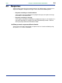
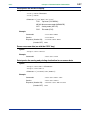
Sets/queries group 1 of output data items
Syntax
:DOUTput:ITEM1 <Numeric>
:DOUTput:ITEM1?
bit7
bit6
<Numeric> =
THD
bit5
bit4
bit3
bit2
bit1
bit0
Phase
Integration Normal
Total
Harmonics Harmonics
angle of
and
measureharmonics
content
level
harmonics
demand
ment
Example
Commands
:DOUT:ITEM1 1
Queries
:DOUT:ITEM1?
Response (Header ON)
:DOUTPUT:ITEM1 1
(Header OFF) 1
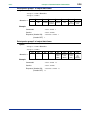
Sets/queries group 2 of output data items
Syntax
:DOUTput:ITEM2 <Numeric>
:DOUTput:ITEM2?
bit7
bit6
bit5
bit4
<Numeric> =
bit3
Minimum
value
(MIN.)
bit2
Maximum
value
(MAX.)
bit1
bit0
Average
value
(AVE.)
Instantaneous
value
(INTER.)
Example
Commands
:DOUT:ITEM2 15
Queries
:DOUT:ITEM2?
Response (Header ON)
:DOUTPUT:ITEM2 15
(Header OFF) 15
IM CW240C-E
1st Edition : Jun.30,2004
2-29
<Chapter 2. Communication Commands>
<Toc>
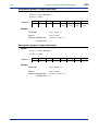
Sets/queries group 3 of output data items
Syntax
:DOUTput:ITEM3 <Numeric>
:DOUTput:ITEM3?
<Numeric> =
bit7
bit6
bit5
bit4
bit3
bit2
bit1
bit0
4-system
load
3-system
load
2-system
load
1-system
load
Example
Commands
:DOUT:ITEM3 15
Queries
:DOUT:ITEM3?
Response (Header ON)
:DOUTPUT:ITEM3 15
(Header OFF) 15
Sets/queries group 4 of output data items
Syntax
:DOUTput:ITEM4 <Numeric>
:DOUTput:ITEM4?
<Numeric> =
bit7
bit6
bit5
bit4
bit3
bit2
bit1
bit0
P
I4
I3
I2
I1
U3
U2
U1
Example
Commands
:DOUT:ITEM4 255
Queries
:DOUT:ITEM4?
Response (Header ON)
:DOUTPUT:ITEM3 255
(Header OFF) 255
IM CW240C-E
1st Edition : Jun.30,2004
2-30
<Chapter 2. Communication Commands>
<Toc>
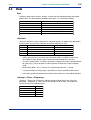
Sets/queries group 5 of output data items
Syntax
:DOUTput:ITEM5 <Numeric1>,<Numeric2>,<Numeric3>,<Numeric4>,
<Numeric5>,<Numeric6>,<Numeric7>,<Numeric8>
:DOUTput:ITEM5?
bit7
<Numeric1> =
<Numeric2> =
<Numeric3> =
<Numeric4> =
<Numeric5> =
<Numeric6> =
<Numeric7> =
bit6
bit5
bit4
bit3
bit2
bit1
bit0
All orders
All odd
All even
bit7
bit6
bit5
bit4
bit3
bit2
bit1
bit0
8th-order
7th
6th
5th
4th
3rd
2nd
1st
bit7
bit6
bit5
bit4
bit3
bit2
bit1
bit0
16th-order
15th
14th
13th
12th
11th
10th
9th
bit7
bit6
bit5
bit4
bit3
bit2
bit1
bit0
24th-order
23th
22th
21th
20th
19th
18th
17th
bit7
bit6
bit5
bit4
bit3
bit2
bit1
bit0
32th-order
31th
30th
29th
28th
27th
26th
25th
bit7
bit6
bit5
bit4
bit3
bit2
bit1
bit0
40th-order
39th
38th
37th
36th
35th
34th
33th
bit7
bit6
bit5
bit4
bit3
bit2
bit1
bit0
48th-order
47th
46th
45th
44th
43th
42th
41th
bit7
bit6
bit5
bit4
bit3
bit2
bit1
bit0
50th-order
49th
<Numeric8> =
Example
Commands
:DOUT:ITEM5 0,255,255,255,255,255,255,
255,3
Queries
:DOUT:ITEM5?
Response (Header ON)
:DOUTPUT:ITEM5 0,255,255,255,255,255,
255,255,3
(Header OFF) 0,255,255,255,255,255,255,255,3
IM CW240C-E
1st Edition : Jun.30,2004
2-31
<Chapter 2. Communication Commands>
<Toc>
Sets/queries the saving destination for output data items
Syntax
:DOUTput:MEDIa <Character>
:DOUTput:MEDIa?
<Character> = {CARD|MEMORY}
Example
Commands
:DOUT:MEDI CARD
Queries
:DOUT:MEDI?
Response (Header ON)
:DOUTPUT:MEDIA CARD
(Header OFF) CARD
Saves measurement data (as with the SAVE key)
Syntax
:DOUTput:SAVE
Example
Commands
:DOUT:SAVE
Sets/queries the state of the saving function for waveform data files
Syntax
:DOUTput:WAVE <Boolean>
:DOUTput:WAVE?
Example
Commands
:DOUT:WAVE ON
Queries
:DOUT:WAVE?
Response (Header ON)
:DOUTPUT:WAVE 1
(Header OFF) 1
Changes/queries a filename
Syntax
:FILEname:CHANge <Character 1>,<Filename 2>,<Filename 3>
<Character 1> = {CARD|MEMORY}
<Filename 2> = Old filename
<Filename 3> = New filename
Example
Commands
:FILE:CHAN CARD,240AM000.CSV,MEASURE.CSV
IM CW240C-E
1st Edition : Jun.30,2004
<Chapter 2. Communication Commands>
<Toc>
2-32
Sets/queries a filename of measurement date
Syntax
:FILEname:MEASure <Character>
:FILEname:MEASure?
<Character> = Character data of up to 8 alphanumeric character
Description
When <Character> is omitted, the filename is cleared.
Example
Commands
:FILE:MEAS 240AM000
Queries
:FILE:MEAS?
Response (Header ON)
:FILENAME:MEASURE 240AM000
(Header OFF) 240AM000
Sets/queries the low-pass filter for frequency source
Syntax
:FILTer <Boolean>
:FILTer?
Example
Commands
:FILT ON
Queries
:FILT?
Response (Header ON)
:FILTER 1
(Header OFF) 1
Sets/queries the measurement frequency
Syntax
:FREQuency <Numeric>
:FREQuency?
<Numeric> = 50/60
Example
Commands
:FREQ 50
Queries
:FREQ?
Response (Header ON)
:FREQUENCY 50
(Header OFF) 50
IM CW240C-E
1st Edition : Jun.30,2004
<Chapter 2. Communication Commands>
<Toc>
2-33
Sets/queries the display holding status
Syntax
:HOLD <Boolean>
:HOLD?
Example
Commands
:HOLD ON
Queries
:HOLD?
Response (Header ON)
:HOLD 1
(Header OFF) 1
Sets/queries the calcutational method
Syntax
:HPA <Numeric>
:HPA?
<Numeric> = 0/1
0:Fundamental wave (FUNDAME. WAVE)
1:U1
Example
Commands
:HPA 0
Queries
:HPA?
Response (Header ON)
:HPA 0
(Header OFF) 0
Sets/queries the hysteresis factor in percentage
Syntax
:HYSTeresis <Numeric>
:HYSTeresis?
<Numeric> = 0 to 10
Example
Commands
:HYST 10
Queries
:HYST?
Response (Header ON)
:HYSTERESIS 10
(Header OFF) 10
IM CW240C-E
1st Edition : Jun.30,2004
<Chapter 2. Communication Commands>
<Toc>
2-34
Sets/queries the ID number
Syntax
:ID <Numeric>
:ID?
<Numeric> = 1 to 999
Example
Commands
:ID 1
Queries
:ID?
Response (Header ON)
:ID 1
(Header OFF) 1
Sets/queries the interval
Syntax
:INTErval <Character>
:INTErval?
<Character>= {WAVE|0.1S|0.2S|0.5S|1S|2S|5S|10S|15S|1M|2M|5M|
10M|15M|30M|1H}
WAVE:1 Single waveform
0.1S:100msec
0.2S:200msec
0.5S:500msec
1S:1sec
2S:2sec
5S:5sec
10S:10sec
15S:15sec
1M:1min
2M:2min
5M:5min
10M:10min
15M:15min
30M:30min
1H:1hour
Example
Commands
:INTE 1S
Queries
:INTE?
Response (Header ON)
:INTERVAL 1S
(Header OFF) 1S
IM CW240C-E
1st Edition : Jun.30,2004
<Chapter 2. Communication Commands>
<Toc>
2-35
Sets/queries the keylock function
Syntax
:KLOCk <Boolean>
:KLOCk?
Example
Commands
:KLOCK ON
Queries
:KLOCK?
Response (Header ON)
:KLOCK 1
(Header OFF) 1
Sets/queries the language
Syntax
:LANGuage <Character>
:LANGuage?
<Character> = {JAPANESE|ENGLISH|GERMAN|FRENCH|ITALIAN|SPANISH}
Example
Commands
:LANG JAPANESE
Queries
:LANG?
Response (Header ON)
:LANGUAGE JAPANESE
(Header OFF) JAPANESE
Sets/queries the number of system loads
Syntax
:LOAD <Numeric>
:LOAD?
<Numeric> = 1 to 4
Example
Commands
:LOAD 1
Queries
:LOAD?
Response (Header ON)
:LOAD 1
(Header OFF) 1
IM CW240C-E
1st Edition : Jun.30,2004
2-36
<Chapter 2. Communication Commands>
<Toc>
Queries the state of integration measurement
Syntax
:MEASure:STATe?
Response
<Numeric> = 0/1/2
0:Halted
1:On standby
2:In progress
Example
Queries
:MEAS:STAT?
Response (Header ON)
:MEASURE:STATE 0
(Header OFF) 0
Queries the date and time of the actual start of integration measurement
Syntax
:MEASure:TIME:STARt?
Response
(Header ON)
:MEASURE:TIME:START <year>,<month>,
<day>,<hour>,<min>,<sec>
(Header OFF)
<year>,<month>,<day>,<hour>,<min>,<sec>
Queries
:MEAS:TIME:STAR?
Response (Header ON)
:MEASURE:TIME:START 2003,8,4,17,0,0
Example
(Header OFF) 2003,8,4,17,0,0
Queries the date and time of the actual stop of integration measurement
Syntax
:MEASure:TIME:STOP?
Response
(Header ON)
:MEASURE:TIME:STOP <year>,<month>,<day>,
<hour>,<min>,<sec>
(Header OFF)
<year>,<month>,<day>,<hour>,<min>,<sec>
Queries
:MEAS:TIME:STOP?
Response (Header ON)
:MEASURE:TIME:STOP 2003,8,4,17,0,0
Example
(Header OFF) 2003,8,4,17,0,0
IM CW240C-E
1st Edition : Jun.30,2004
2-37
<Chapter 2. Communication Commands>
<Toc>
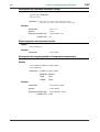
Queries measurement values
Syntax
:MEASure:VALUe?
Response
(Header ON)
<Header><Numeric>
(Header OFF)
<Numeric>
:Outputs text of the items specified by the ":DOUTput:ITEM<x>" command.
<Header> = Same as the header used for saving the detected fluctuation values
as files.
<Numeric> =
Date
yyyy/mm/dd
Time
hh:mm:ss
Elapsed Time or Elapsed Period
hhhhh:mm:ss
Electric energy
±1.23456E+00
Data other than electric energy
±1.234E+00
Example
Queries
:MEAS:VALU?
Response (Header ON)
DATE 2003/08/12,TIME 15:25:00,|
ETIME 00:01:00,U1_INST(V),|
+1.000E+02,.....
(Header OFF) 2003/08/12,15:25:00,00:10:00,|
+1.000E+02,.....
Queries the file name of internal memory
Syntax
:MEMOry:DIREctory? <Character>
<Character> = {MEAS|INST|WAVE|SET|ALM|BMP}
MEAS:Measurement file
INST:Short interval file
WAVE:Waveform file
SET:Setting file
ALM:Detected voltage fluctuation file
(Voltage quality)
BMP:Screen file
(Hard copy)
Response
<Filename>,<Size>,...
Example
Queries
:MEMO:DIRE? MEAS
Response
240AM000,1024
IM CW240C-E
1st Edition : Jun.30,2004
2-38
<Chapter 2. Communication Commands>
<Toc>
Formats data files on internal memory
Syntax
:MEMOry:FORMat
Example
Commands
:MEMO:FORM
Transfers the file from internal memory
Syntax
:MEMOry:PICKout? <Filename 1>,<Numeric2>,<Numeric3>
<Filename 1> = A filename to transfer
<Numeric2> = Start position
<Numeric3> = Stop position
Response
STX(02)+Transferred data +ETX(03)
Example
Queries
:MEMO:PICK? 240AM000.CSV,1,1000
Response
STX(02)CW240,.....ETX(03)
Returns the data of 240AM000.CSV file (1 byte to
1000 bytes)
NOTE
To execute this command, specify the RS-232 handshake settings between the CW240
and a personal computer to "CS/RS" beforehand.
Deletes a setting file from internal memory
Syntax
:MEMOry:SETTing:DELEte <Character>
<Character> = Character data of up to 8 alphanumeric character
Example
Commands
:MEMO:SETT:DELE 240MC000.SET
Formats setting files on internal memory
Syntax
:MEMOry:SETTing:FORMat
Example
Commands
:MEMO:SETT:FORM
IM CW240C-E
1st Edition : Jun.30,2004
2-39
<Chapter 2. Communication Commands>
<Toc>
Loads a setting file from internal memory
Syntax
:MEMOry:SETTing:LOAD <Character>
<Character> = Character data of up to 8 alphanumeric character
Example
Commands
:MEMO:SETT:LOAD 240MC000.SET
Saves a setting file to internal memory
Syntax
:MEMOry:SETTing:SAVE <Character >
<Character> = Character data of up to 8 alphanumeric character
Example
Commands
:MEMO:SETT:SAVE 240MC000.SET
Sets/queries whether the reactive power method is set to ON or OFF
Syntax
:OPERationvar <Boolean>
:OPERationvar?
Example
Commands
:OPER ON
Queries
:OPER?
Response (Header ON)
:OPERATIONVAR 1
(Header OFF) 1
Sets/queries the order of harmonics’ bar graphs to display
Syntax
:ORDEr <Character>
:ORDEr?
<Character> = {ALL|ODD}
ALL: All orders
ODD: Odd
Example
Commands
:ORDE ALL
Queries
:ORDE?
Response (Header ON)
:ORDER ALL
(Header OFF) ALL
IM CW240C-E
1st Edition : Jun.30,2004
<Chapter 2. Communication Commands>
<Toc>
2-40
Resets the system
Syntax
:RESEt
Example
Commands
:RESE
Sets/queries the sampling method
Syntax
:SAMPling <Character>
:SAMPLing?
<Character> = {PLL|FIX}
PLL:PLL
FIX:Fixed clock
Example
Commands
:SAMP PLL
Queries
:SAMP?
Response (Header ON)
:SAMPLING PLL
(Header OFF) PLL
Sets/queries the frequency source
Syntax
:SOURce <Character>
:SOURce?
<Character> = {U1|U2|U3}
U1: Voltage input terminal 1
U2: Voltage input terminal 2
U3: Voltage input terminal 3
Example
Commands
:SOUR U1
Queries
:SOUR?
Response (Header ON)
:SOURCE U1
(Header OFF) U1
Starts integration measurement
Syntax
:STARt:EXECute
Example
Commands
:STAR:EXEC
IM CW240C-E
1st Edition : Jun.30,2004
2-41
<Chapter 2. Communication Commands>
<Toc>
Sets/queries the starting method of integration measurement
Syntax
:STARt:METHod <Character>
:STARt:METHod?
<Character> = {MANUAL|TIME|JUST}
MANUAL: Manual
TIME:
Time
JUST:
Measurement starts at the optimum time for the set
interval.
Example
Commands
:STAR:METH TIME
Queries
:STAR:METH?
Response (Header ON)
:START:METHOD TIME
(Header OFF) TIME
Sets/queries the date and time of the start of integration measurement
Syntax
:STARt:TIME <year>,<month>,<day>,<hour>,<min>
:STARt:TIME?
Example
Commands
:STAR:TIME 2003,8,4,16:20
Queries
:STAR:TIME?
Response (Header ON)
:START:TIME 2003,8,4,16:20
(Header OFF) 2003,8,4,16:20
Queries the error codes that occurred
Syntax
:STATus:ERRor?
Example
Queries
:STAT:ERR?
Response (Header ON)
:STAT:ERR 0
(Header OFF) 0
IM CW240C-E
1st Edition : Jun.30,2004
<Chapter 2. Communication Commands>
<Toc>
2-42
Sets/queries the reference (standard) voltage
Syntax
:STDVoltage <Numeric>
:STDVoltage?
<Numeric> = 100/101/110/120/200/202/208/220/
230/240/277/346/380/400/480/600/1000
Example
Commands
:STDV 100
Queries
:STDV?
Response (Header ON)
:STDVOLTAGE 100
(Header OFF) 100
Stops integration measurement forcibly
Syntax
:STOP:EXECute
Example
Commands
:STOP:EXEC
Sets/queries the stopping method of integration measurement
Syntax
:STOP:METHod MANUAL/TIME/TIMER
:STOP:METHod?
<Character> = {MANUAL|TIME|TIMER}
MANUAL: Manual
TIME:
Time
TIMER:
Timer
Example
Commands
:STOP:METH TIME
Queries
:STOP:METH?
Response (Header ON)
:STOP:METHOD TIME
(Header OFF) TIME
IM CW240C-E
1st Edition : Jun.30,2004
2-43
<Chapter 2. Communication Commands>
<Toc>
Sets/queries the date and time of the stop of integration measurement
Syntax
:STOP:TIME <year>,<month>,<day>,<hour>,<min>
:STOP:TIME?
Example
Commands
:STOP:TIME 2003,8,4,16:20
Queries
:STOP:TIME?
Response (Header ON)
:STOP:TIME 2003,8,4,16:20
(Header OFF) 2003,8,4,16:20
Sets/queries the date
Syntax
:SYSTem:DATE <year>,<month>,<day>
:SYSTem:DATE?
Example
Commands
:SYST:DATE 2003,8,4
Queries
:SYST:DATE?
Response (Header ON)
:SYSTEM:DATE 2003,8,4
(Header OFF) 2003,8,4
Sets/queries the time
Syntax
:SYSTem:TIME <hour>,<min>,<sec>
:SYSTem:TIME?
Example
Commands
:SYST:TIME 16,50,0
Queries
:SYST:TIME?
Response (Header ON)
:SYST:TIME 16,50,0
(Header OFF) 16,50,0
IM CW240C-E
1st Edition : Jun.30,2004
2-44
<Chapter 2. Communication Commands>
<Toc>
Sets/queries the method of Total Harmonic Distortion
Syntax
:THD <Character>
:THD?
<Character> = {F|R}
F:THD-F
R:THD-R
Example
Commands
:THD F
Queries
:THD?
Response (Header ON)
:THD F
(Header OFF) F
Sets/queries the threshold value of voltage dips
Syntax
:THREshold:DIP <Numeric>
:THREshold:DIP?
<Numeric> = 0 to 100
Example
Commands
:THRE:DIP 90
Queries
:THRE:DIP?
Response (Header ON)
:THRESHOLD:DIP 90
(Header OFF) 90
Sets/queries the threshold value of momentary voltage interruptions
Syntax
:THREshold:INTErruption <Numeric>
:THREshold:INTErruption?
<Numeric> = 0 to 100
Example
Commands
:THRE:INTE 90
Queries
:THRE:INTE?
Response (Header ON)
:THRESHOLD:INTERRUPTION 90
(Header OFF) 90
IM CW240C-E
1st Edition : Jun.30,2004
<Chapter 2. Communication Commands>
<Toc>
2-45
Sets/queries the threshold value of voltage swells
Syntax
:THREshold:SWELl <Numeric>
:THREshold:SWELl?
<Numeric> = 0 to 200
Example
Commands
:THRE:SWEL 100
Queries
:THRE:SWEL?
Response (Header ON)
:THRESHOLD:SWELL 100
(Header OFF) 100
Sets/queries the end -of- measurement timer setting
Syntax
:TIMEr <Numeric1>,<Numeric2>,<Numeric3>
:TIMEr?
<Numeric1> = Hour data (0 to 8784)
<Numeric2> = Minute data (0 to 59)
<Numeric3> = Second data (0 to 59)
Example
Commands
:TIME 1,0,0
Queries
:TIME?
Response (Header ON)
:TIMER 1,0,0
(Header OFF) 1,0,0
Sets/queries whether or not to detect voltage fluctuation (voltage quality)
Syntax
:VDETect:MEASure <Boolean>
:VDETect:MEASure?
Example
Commands
:VDET:MEAS ON
Queries
:VDET:MEAS?
Response (Header ON)
:VDETECT:MEASURE 1
(Header OFF) 1
IM CW240C-E
1st Edition : Jun.30,2004
2-46
<Chapter 2. Communication Commands>
<Toc>
Queries detected voltage fluctuation (voltage quality) values
Syntax
:VDETect:VALUe?
Response
(Header ON)
<Number of detected values>,<Header><Numeric>
(Header OFF)
<Number of detected values>,<Numeric>
<Number of detected values> = 0 to 100
<Header> = Same as the header used for saving the detected fluctuation values
as files.
Header item
Detected value data
Number
1 to 100
Detection date
yyyy/mm/dd
Detection time
hh:mm:ss
Detection time (msec)
nnn
Fluctuation type
SWELL, DIP, INTER
<Numeric> =
Voltage input
Wirings other than 3-phase 3-wire and
1-phase 3-wire
U1, U2, U3
3-phase 3-wire and 1-phase 3-wire
U1_3P, U2_3P, U3_3P
U1_1P, U2_1P
Start/end
IN, OUT
Detected RMS voltage (V)
0.000E±00
Time period
hhhh:mm:ss
Time period (msec)
nnn
Example
Queries
:VDET:VALU?
Response (Header ON)
5,NO 1,DATE 2003/08/12,
TIME 15:25:00,000,TYPE SWELL,.....
(Header OFF) 5,2003/08/12,15:25:00,000,SWELL,.....
Sets/queries the voltage range
Syntax
:VOLT:RANGe <Numeric>
:VOLT:RANGe?
<Numeric> = 150/300/600/1000
Example
Commands
:VOLT:RANG 150
Queries
:VOLT:RANG?
Response (Header ON)
:VOLT:RANGE 150
(Header OFF) 150
IM CW240C-E
1st Edition : Jun.30,2004
2-47
<Chapter 2. Communication Commands>
<Toc>
Sets/queries the VT ratio
Syntax
:VT <Numeric>
:VT?
<Numeric> = 0.01 to 9999.99
Example
Commands
:VT 2.0
Queries
:VT?
Response (Header ON)
:VT 2.00
(Header OFF) 2.00
Executes clearing of integrated values to zero
Syntax
:WH:CLEAr
Example
Commands
:WH:CLEA
Sets/queries the position of the decimal point of electric energy (Interval of
Demand measure mode)
Syntax
:WH:INTErval:DIGIt <Character>
:WH:INTErval:DIGIt?
<Character> = {STD|000.000|0000.00|00000.0|000000|AUTO}
Example
Commands
:WH:INTE:DIGI STD
Queries
:WH:INTE:DIGI?
Response (Header ON)
:WH:INTERVAL:DIGIT STD
(Header OFF) STD
Sets/queries the unit of electric energy (Interval of Demand measure mode)
Syntax
:WH:INTErval:UNIT <Character>
:WH:INTErval:UNIT?
<Character> = {MWH|WHH|KWH|MAWH|GWH}
Example
Commands
:WH:INTE:UNIT KWH
Queries
:WH:INTE:UNIT?
Response (Header ON)
:WH:INTERVAL:UNIT KWH
(Header OFF) KWH
IM CW240C-E
1st Edition : Jun.30,2004
2-48
<Chapter 2. Communication Commands>
<Toc>
Sets/queries the position of the decimal point of electric energy
Syntax
:WH:TOTAl:DIGIt <Character>
:WH:TOTAl:DIGIt?
<Character> = {STD|000.000|0000.00|00000.0|000000|AUTO}
Example
Commands
:WH:TOTA:DIGI STD
Queries
:WH:TOTA:DIGI?
Response (Header ON)
:WH:TOTAL:DIGIT STD
(Header OFF) STD
Sets/queries the unit of electric energy
Syntax
:WH:TOTAl:UNIT <Character>
:WH:TOTAl:UNIT?
<Character> = {MWH|WH|KWH|MAWH|GWH}
Example
Commands
:WH:TOLA:UNIT KWH
Queries
:WH:TOTA:UNIT?
Response (Header ON)
:WH:TOTAL:UNIT KWH
(Header OFF) KWH
Sets/queries the wiring type
Syntax
:WIRIng <Character>
:WIRIng?
<Character> = {1P2W|1P3W|1P3W3I|3P3W2I|3P3W3I|3P4W|3P3W4I|
3P3W+1P3W}
Example
Commands
:WIRI 1P2W
Queries
:WIRI?
Response (Header ON)
:WIRING 1P2W
(Header OFF) 1P2W
IM CW240C-E
1st Edition : Jun.30,2004
<Chapter 2. Communication Commands>
<Toc>
2.8
2-49
Valid/Invalid Communication Command Tables
The following tables list valid/invalid commands in each measurement mode and setting.
: Indicates the command is valid.
: Indicates the command is invalid.
State
Command
Integration
measurement halted
Continuous
Hold
Integration
measurement on
standby
Continuous Hold
Integration
measurement in
progress
Continuous Hold
*CLS
*IDN?
:1PCOnnect
:1PCOnnect?
:AINP:CH1
:AINP:CH1?
:AINP:CH2
:AINP:CH2?
:AOUT:CH1
:AOUT:CH1?
:AOUT:CH2
:AOUT:CH2?
:AOUT:CH3
:AOUT:CH3?
:AOUT:CH4
:AOUT:CH4?
:AVERaging
:AVERaging?
:BACKlight
:BACKlight?
:BEEP
:BEEP?
:CARD:DELEte
:CARD:DIREctory?
:CARD:DOWNload
:CARD:DOWNload:ALL
:CARD:FORMat
:CARD:PICKout?
:CARD:SETTing:LOAD
:CARD:SETTing:SAVE
:CARD:STATe?
:CLAMp
:CLAMp?
:COMMunicate:HEADer
:COMMunicate:HEADer?
:CONNect
:CONNect ?
:CONTrast
:CONTrast?
:CT
:CT?
:CURRent:RANGe
:CURRent:RANGe?
IM CW240C-E
1st Edition : Jun.30,2004
<Chapter 2. Communication Commands>
<Toc>
State
Command
Integration
measurement halted
Continuous
Hold
Integration
measurement on
standby
Continuous Hold
2-50
Integration
measurement in
progress
Continuous Hold
:DISPlay:MEASure
:DISPlay:MEASure ?
:DISPlay:MODE
:DISPlay:MODE?
:DOUTput:COPY:DATAout
:DOUTput:COPY:MEDIa
:DOUTput:COPY:MEDIa?
:DOUTput:ITEM1
:DOUTput:ITEM1?
:DOUTput:ITEM2
:DOUTput:ITEM2?
:DOUTput:ITEM3
:DOUTput:ITEM3?
:DOUTput:ITEM4
:DOUTput:ITEM4?
:DOUTput:ITEM5
:DOUTput:ITEM5?
:DOUTput:MEDIa
:DOUTput:MEDIa?
:DOUTput:SAVE
:DOUTput:WAVE
:DOUTput:WAVE?
:FILEname:CHANge
:FILEname:MEASure
:FILEname:MEASure?
:FILTer
:FILTer?
:FREQuency
:FREQuency?
:HOLD
:HOLD?
:HPA
:HPA?
:HYSTeresis
:HYSTeresis?
:ID
:ID?
:INTErval
:INTErval?
:KLOCk
:KLOCk?
:LANGuage
:LANGuage?
:LOAD
:LOAD?
:MEASure:STATe?
:MEASure:TIME:START?
:MEASure:TIME:STOP?
:MEASure:VALUe?
IM CW240C-E
1st Edition : Jun.30,2004
<Chapter 2. Communication Commands>
<Toc>
State
Command
Integration
measurement halted
Continuous
Hold
Integration
measurement on
standby
Continuous Hold
2-51
Integration
measurement in
progress
Continuous Hold
:MEMOry:DIREctory?
:MEMOry:FORMat
:MEMOry:PICKout?
:MEMOry:SETTing:DELEte
:MEMOry:SETTing:FORMat
:MEMOry:SETTing:LOAD
:MEMOry:SETTing:SAVE
:OPERationvar
:OPERationvar?
:ORDEr
:ORDEr?
:RESEt
:SAMPling
:SAMPling?
:SOURce
:SOURce?
:STARt:EXECute
:STARt:METHod
:STARt:METHod?
:STARt:TIME
:STARt:TIME?
:STATus:ERRor?
:STDVoltage
:STDVoltage?
:STOP:EXECute
:STOP:METHod
:STOP:METHod?
:STOP:TIME
:STOP:TIME?
:SYSTem:DATE
:SYSTem:DATE?
:SYSTem:TIME
:SYSTem:TIME?
:THD
:THD?
:THREshold:DIP
:THREshold:DIP?
:THREshold:INTErruption
:THREshold:INTErruption?
:THREshold:SWELl
:THREshold:SWELl?
:TIMEr
:TIMEr?
IM CW240C-E
1st Edition : Jun.30,2004
<Chapter 2. Communication Commands>
<Toc>
State
Command
Integration
measurement halted
Continuous
Hold
Integration
measurement on
standby
Continuous Hold
2-52
Integration
measurement in
progress
Continuous Hold
:VDETect:MEASure
:VDETect:MEASure?
:VDETect:VALUe?
:VOLT:RANGe
:VOLT:RANGe?
:VT
:VT?
:WH:CLEAr
:WH:INTErval:DIGIt
:WH:INTErval:DIGIt?
:WH:INTErval:UNIT
:WH:INTErval:UNIT?
:WH:TOTAl:DIGIt
:WH:TOTAl:DIGIt?
:WH:TOTAl:UNIT
:WH:TOTAl:UNIT?
:WIRIng
:WIRIng?
IM CW240C-E
1st Edition : Jun.30,2004
i
<Int> <Toc>
Revision Information
● Title
: CW240 CLAMP-ON POWER METER Communication Functions Manual
● Manual No. : IM CW240C-E
Jun. 2004/1st Edition
Newly published
Written by
Yokogawa M&C Corporation
Yokogawa M&C Corporation
Published by Yokogawa M&C Corporation
2-9-32 Nakacho, Musashino-shi, Tokyo 180-8750, JAPAN
IM CW240C-E
1st Edition : Jun.30,2004
Blank Page