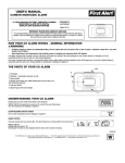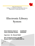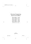
1
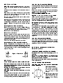
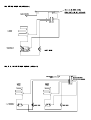
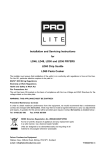
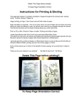
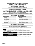
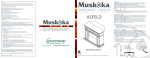
LD3, LD4, LD5, LD6, LD7, LD8, LD9, LD13, LD14
GRIDDLES
Important Installation Information
The installer must ensure that installation of the unit(s) is in conformity with
regulations in force at the time. For the UK, particular attention requires to be paid
to:BS7671 IEE Wiring Regulations
Electricity at Work Regulations
Health and Safety at Work Act
Fire Precautions Act
The unit has been CE-marked on the basis of compliance with the Low Voltage and
EMC Directives for the voltage stated on the data plate.
WARNING: THIS APPLIANCE MUST BE EARTHED!
Preventive Maintenance Contract
In order to obtain maximum performance from the equipment, we would recommend
that a maintenance contract be arranged with AFE Service Line. Visits may then be
made at agreed intervals to carry out adjustments and repairs. A quotation for this
service will be provided upon request. Contact AFE Service Line as detailed below:Tel: 01438 363 000
Fax: 01438 369 900
Falcon Foodservice Equipment
Wallace View, Hillfoots Road, Stirling. FK9 5PY. Scotland.
Tel: 01324 554 221
Fax: 01324 552 211
e-mail: [email protected]
T100324 Ref. 4
gk13
gk34
gk12
gk13
gk34
gk34
gk34
gk34
gk34
gnitaR esuF
A31
A31
A31
A31
A31
a/n
a/n
a/n
a/n
gnitaR rewoP
Wk57.2
Wk57.2
Wk57.2
Wk57.2
Wk57.2
Wk6
Wk5.5
Wk5.5
Wk5.5
.lC raeR/ediS
mm051
mm051
mm051
mm051
mm051
mm051
mm051
mm051
mm051
ecnaraelC lacitreV
mm009
mm009
mm009
mm009
mm009
mm009
mm009
mm009
mm009
thgieH
mm582
mm582
mm582
mm582
mm582
mm582
mm582
mm582
mm582
htpeD
mm006
mm006
mm006
mm006
mm006
mm006
mm006
mm006
mm006
htdiW
mm054
mm006
mm003
mm054
mm006
mm006
mm006
mm006
mm006
epyT
C
C
C
C
C
C
C
C
C
etalP elddirG 3DL
etalP elddirG 4DL
etalP elddirG 5DL
etalP elddirG 6DL
etalP elddirG 7DL
etalP elddirG 8DL
etalP elddirG 9DL
etalP elddirG 31DL
etalP elddirG 41DL
elbaT noitamrofnI noitallatsnI lacinhceT
.draob noitubirtsid ro rotpada ,gulp eht ni desu eb ot seriuqer esuf A51 a ,desu si gulp fo epyt rehtona fI
.desu si gulp pma 31 a fi esuf pma 31 a yb detcetorp eb tsum tinu ehT :gnitaR esuF A31 * etoN
ledoM
thgieW
tinU gnidnatseerF = F
tinU potretnuoC = C
CA N2 V004 ro CA V032 ta sgnitaR rewoP
tinU gnitnuoM dnatS = S
tinU esaB = B
SECTION 1 - SITING
PRO-LITE models have been designed in a modular
form which consists of base, counter and free-standing
units.
Information which relates to individual models is listed in
Table 1.
Free-standing and base models should be installed
upon a firm, level surface and adjustable feet are
provided for levelling purposes.
Counter units must be positioned upon a table, counter
or similar surface.
Vertical and horizontal clearances required from the top
and sides of a particular unit to any overlying
combustible surface (ie wall, partition, etc) are listed in
Table 1. Relevant fire regulations must be complied
with.
Mounting Counter Units on the Oven
When mounting a counter unit upon a PRO-LITE oven,
it is recommended that units which carry liquids,
i.e. fryers and bain marie, are secured as follows:
Remove oven outer back panel.
Remove oven crown plate.
Position unit(s) which require to be secured upon oven.
Secure hob unit(s) to oven through side flange centre
holes into the threaded inserts in the base(s) of the hob
unit(s). Use fixings provided (packed separately) and
replace oven back panel.
The unit is now ready for electrical connection.
Mounting Counter Units upon a Hotcupboard
Kestrel hotcupboards are designed to be used in
conjunction with counter models. Assembly is achieved
by means of two shouldered fixings being applied to the
underside of a top unit from inside a base appliance as
detailed in Figure 1.
Figure 1 - Front View
SECTION 2 ELECTRICAL SUPPLY AND CONNECTION
Electrical ratings are as stated on the unit data
plate. The listing in Table 1 is based on standard UK
specification at 230V~.
Wiring must be executed in accordance with the
regulations listed in this booklet.
WARNING: Each individual appliance must be
earthed!
After completion of installation, the method of operation
should be demonstrated to the kitchen staff.
The isolating switch location, for use in an emergency
or during cleaning should also be pointed out.
LD3, LD4, LD5, LD6 and LD7 GRIDDLES
These models are designed to be connected to a single
phase AC supply using the 2 metre mains lead fitted as
standard.
Wires are coloured in accordance with the following
code and should be connected to the plug as follows:
EARTH to terminal marked E or
coloured GREEN or GREEN/YELLOW.
NEUTRAL to terminal marked N or coloured BLACK.
LIVE to terminal marked L or coloured RED.
Units which receive power from a plug, adaptor or
distribution board must be individually protected by a
fuse with an appropriate rating. (See Table 1)
For models with two mains leads, each lead requires to
be protected by a fuse with an appropriate rating.
(See Table 1)
Any replacement supply cable must be 1.5mm2, cord
code designation 245 IEC 57 (CENELEC H05 RN-F).
For internal connection, outer sheathing must be
stripped 140mm from cable end. The live and neutral
conductors must be trimmed so that the Earth
conductor is longer by 50mm. Pass inlet cable through
the rear panel cord grip and ensure that the cable is
routed without leaving excessive free length inside the
appliance.
LD8, LD9, LD13 and LD14 GRIDDLES
This model is designed to be connected to a single
phase AC supply. Electrical supply must be installed
using a suitable isolating switch with a minimum contact
separation of 3mm in all poles.
SECTION 3 - USING AND CLEANING
PRO-LITE UNITS
IMPORTANT: GENERAL NOTES ON CLEANING
Disconnect unit from electricity supply prior to
cleaning
Never use a coarse abrasive to clean exterior
panels. A soft cloth with a warm water and
detergent solution is sufficient.
Never attempt to steam clean a unit or hose it down
with a jet of water.
LD3 and LD4 CAST IRON GRIDDLES
LD5, LD6, LD7, LD8, LD9 and LD14 MACHINED
STEEL GRIDDLES
Plate Control Switch
The griddle is controlled
by a switch which offers
six individual heat
settings.
Prior to using the unit for
the first time, season the
plate accordingly as
detailed in the following
procedure.
Wash plate surface to remove the layer of protective
grease.
Brush surface liberally with frying oil and cover plate
evenly with a 10mm layer of salt.
Turn griddle switch to Setting 5 and heat for 25 minutes.
Switch off, allow salt to cool and remove salt without
scratching plate surface.
Dress plate surface with oil and heat until this oil burns
into the plate and forms a skin.
Re-oil plate surface and the griddle is now ready to use.
Cooking on a Griddle
Allow 20 to 30 minutes pre-heat time to reach the
working temperature. Getting the best out of this type of
unit is largely down to experience, coupled with the
requirements of a particular task. It is not possible to
provide detailed instructions for the preparation of a
particular item however the plate temperature requires
to be regulated for different needs.
i.e. fried eggs require a LOW setting whilst meat (steak,
chops, beefburgers, etc) needs a much higher setting
for successful results.
Cleaning a Cast Iron or Machined Steel Griddle
Surplus fat, etc. collected during cooking should be
drained into the removable receptacle. Take care to
avoid this becoming overfilled by cleaning at least daily.
Use a broad metal scraper to remove heavy deposits
from the plate surface. This should be carried out during
cleaning sessions and from time to time during long
cooking periods. To clean the plate, turn the unit off and
allow it to cool until hand warm. Use a mild scourer to
clear any food deposit. Rinse with clean water and dry
thoroughly. Lightly re-oil the surface after cleaning.
The plate surface may require to be re-seasoned should
the non-stick property deteriorate.
Cleaning a Chrome Griddle
It is essential that the cooking surface of a chrome
griddle be cleared of debris continually during operation.
If this practice is not observed then debris will build up
on the surface and carbonise.
The following procedure requires to be carried out daily.
The special plate surface is designed to be cleaned with
cold water, a cleaner sanitiser and Palmetto brush.
NEVER USE A WIRE BRUSH. The plate surface will
release burned-on particles when cold water is applied
to it.
1. Plate temperature should be approximately 160oC.
2. Pour on enough cold water to cover the plate surface.
3. Use the Palmetto brush to sweep the loose particles
and water into a the drain bucket.
4. Sprinkle the cleaning sanitiser liberally over the
griddle surface and wipe it away using a soft towel.
5. With a damp cloth, wipe away any excess cleanser
and polish the plate surface with a dry towel.
Falcon recommend a cleaner sanitiser such as ENDBAC, a product of Johnson Wax Ltd. Further information on the application of ENDBAC can be obtained by
calling the following free hotline number, 0800 525 525.
SECTION 4 - SERVICING
LD3, LD4, LD5, LD6, LD7, LD8 and LD9
LD13 and LD14
SERVICE ACCESS
Base Plate
Upturn unit and rest it at the edge of a worksurface with
rear upstand overhanging the edge.
Undo base plate fixings to remove the base plate.
FUNCTIONAL COMPONENTS
Temperature Control.
Remove base panel.
Remove control knob.
Remove electrical connections, noting their positions.
For units with thermostat, carefully remove the phial
from the retaining clips and clear the structure.
Undo fixings which secure the control to the panel and
remove.
Replace in reverse order.
Elements
Remove base plate, insulation plate and clamp plate.
Undo electrical connections, noting the positions.
Undo element fixings and remove.
Replace in reverse order.
Terminal Block
Remove base plate.
Remove the electrical connections at terminal block,
noting the positions.
Undo fixings which secure the block to the unit and
remove.
Replace in reverse order.
Cable
Remove base plate.
Undo mains cable cord grip at unit rear.
Undo electrical connections at terminal block and
remove cable.
Replace in reverse order. Ensure cable is fed through
securing clamp and pulled taut before tightening clamp.
PRO-LITE GRIDDLE SPARES
735230001
735020000
735020005
735020006
735020001
735020002
735020003
735020004
735120013
735110110
Control Knob
Thermostat for
LD5, LD6, LD7, LD9, LD13, LD14
Thermostat for LD3, LD4
Thermostat for LD8
2.75kW Element for 300mm wide unit
2.75kW Element for 450mm wide unit
2.75kW Element for 600mm wide unit
6kW Element for 600mm wide unit
Amber Neon
Supply Cable
LD3, LD4, LD5 LD6 and LD7
WIRING DIAGRAM (AW39522)
LD8 WIRING DIAGRAM (AW39937)
LD9, LD13, LD14 WIRING DIAGRAM (AW39714)