1
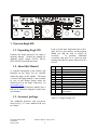
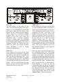
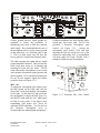
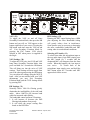
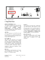
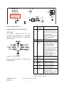
Table of Contents 1. Your new Eagle 599 _________________________________________________________ 3 1.1. Unpacking Eagle 599 _____________________________________________________________ 3 1.2. About this Manual _______________________________________________________________ 3 1.3. Accessory package _______________________________________________________________ 3 1.4. Connection to Antenna & Power Supply _____________________________________________ 4 1.5. A word about grounding __________________________________________________________ 4 1.6. Philosophy of design _____________________________________________________________ 5 1.7. Configuration Menu _____________________________________________________________ 6 2. Easy Operation Guide _______________________________________________________ 7 2.1. General Operations ______________________________________________________________ 7 2.2. SSB Mode Operation ____________________________________________________________ 14 2.3. CW Mode Operation ____________________________________________________________ 18 2.4. AM Mode Operation ____________________________________________________________ 19 2.5. FM Mode Operation ____________________________________________________________ 19 2.6. Mobile Operation _______________________________________________________________ 19 2.7. Digital Mode Operation__________________________________________________________ 19 2.8. Internal Hardware Noise Blanker _________________________________________________ 19 2.9. Internal Tuner _________________________________________________________________ 20 2.10. Optional Filter Installation ______________________________________________________ 21 3. Eagle Rear Panel __________________________________________________________ 22 4. Accessory Devices _________________________________________________________ 24 4.1. Using the 712 USB/Soundcard Interface ____________________________________________ 24 4.2. Interfacing to a computer and firmware updates _____________________________________ 24 4.3. List of Optional Accessories For The Eagle _________________________________________ 26 5. Specifications _____________________________________________________________ 27 5.1. Transceiver Specifications _______________________________________________________ 27 5.2. Transceiver Block Diagram ______________________________________________________ 30 6. In Case of Difficulty ________________________________________________________ 32 7. Warranty & Return Policy ___________________________________________________ 34 8. Addendum A (Firmware Version 1.682) ________________________________________ 35 9. Addendum B (added January 13, 2011) ________________________________________ 36 9.1. FM CTCSS Tones ______________________________________________________________ 36 9.2. Retaining User Settings __________________________________________________________ 36 599 / Eagle Users manual Part #74447 Printed in USA Release 1.009 CE – April 15, 2015 1 9.3. Proper Tuner Operation _________________________________________________________ 37 9.4. High Current Protection _________________________________________________________ 37 9.5. Temperature Protection _________________________________________________________ 37 10. Addendum C (added February 21, 2011) _____________________________________ 38 10.1. Squelch Clarification ___________________________________________________________ 38 10.2. Utilization of the optional 15k filter for FM Reception _______________________________ 38 10.3. Auxiliary Connectors ___________________________________________________________ 38 11. Addendum D (added March 4, 2011) ________________________________________ 39 EC Declaration of Conformity ___________________________________________________ 40 599 / Eagle Users manual Part #74447 Printed in USA Release 1.009 CE – April 15, 2015 2 A=B A/B TEN-TEC VOX NB EAGLE AF MR AGC LOCK AN PRE NR ATTN SP-CW MIC FAST RF RIT MOD PWR TUNE BW PBT SQL MON FNC BAN 1. Your new Eagle 599 1.1. Unpacking Eagle 599 Examine the Eagle transceiver for signs of shipping damage. Should any damage be apparent, please contact Ten-Tec Service (865) 428-0364 to handle the claim. 1.2. About this Manual A complete description of the features and functions on the Eagle 599 are included within the pages of this manual. The latest version of the Eagle manual is also available to view in pdf format located under the download tab on the Eagle Transceiver via www.tentec.com. You may also find firmware updates plus a full set of schematic diagrams at this same web location. 1.3. Accessory package Look over the items listed and refer to the 5 digit Ten-Tec part number and description should you find the need to replace an accessory. To purchase additional accessories and parts or to report an item missing from this list, please contact Ten-Tec Service. Qty Part # Description 1 1 1 1 1 2 1 1 1 1 1 702 27091 35241 35263 38040 41073 46214 74020 74244 74447 74450 1 74454 Dynamic Hand Mic Auto Style Fuse, 25 Amp 32V 8 PIN DIN Connector Plug – Stereo, 3.5MM (1/8) Allen Wrench, 0.050 Hex Fork Terminal Cable Assembly 4 Ft Warranty card Standard Warranty Sheet Manual for 599 How do I become a Ten-Tec Ambassador Eagle Quick Start Guide Table 1.3-1 Eagle Packing List The additional hardware and accessories listed in Fig 1.3-1 come standard with your new Eagle. 599 / Eagle Users manual Part #74447 Printed in USA Release 1.009 CE – April 15, 2015 3 1.4. Connection to Antenna & Power Supply The Eagle is designed for use with any antenna system providing a 50 Ohm resistive impedance at the desired operating frequency. Every effort should be made to ensure the impedance of the antenna system is as close as possible to the specified 50-Ohm value. Note: that the “G5RV” type antenna and some Windom’s do not provide 50-Ohm impedance on all HF Amateur bands, and an external wide-range antenna coupler or the optional model AT599K Eagle internal auto tuner may be needed with this type antenna. Any antenna to be used with the Eagle must, ultimately, be fed with 50 Ohm coaxial cable. The Eagle transceiver requires a source of well-filtered and regulated DC voltage. The supply voltage on the Eagle is 13.8 Vdc nominal +/- 15% to allow for mobile and battery operation. The voltage source must be capable of supplying 23 amperes continuous duty. The model 940 or 941 TenTec power supplies will meet or exceed your voltage and current requirements. We recommend using the included DC power cable (P/N 46214). Use of #12 stranded wire is recommended for mobile and in home use to accommodate the required current demand during transmit. 1.5. A word about grounding A good ground system is essential for optimum operation of any HF transmitter. The best solution is to connect all the station equipment to a single ground connection. Refer to Local and National Electrical Codes before making any connections with the Eagle. Another source of information on grounding can be found in the ARRL Handbook. A good ground system can contribute to the station efficiency in a number of ways including minimizing the possibility of electrical shock, and minimizing RF currents flowing on the shield of the coax cable causing interference to electrical equipment and transceiver accessories. It is critical that the power supply, the Eagle, and other equipment in the station be properly grounded to an Earth ground. Improper grounding can lead to various issues, including RFI, ground loops, or even death. Therefore it is extremely important to refer to the Local and National Electrical Codes and ARRL Handbook with regards to grounding. Note: Always enable the power source first and then the transceiver. If a generator or battery connected to a charger is used to supply the DC source, always turn off the transceiver before starting or shutting off the DC source equipment. These recharging devices often generate large voltage spikes that can damage the transceiver. 599 / Eagle Users manual Part #74447 Printed in USA Release 1.009 CE – April 15, 2015 4 resulting audio appears at the speaker and line outputs. 1.6. Philosophy of design With the Model 599 Eagle, Ten-Tec has created a transceiver combining simplified controls and ease of operation with the excellent performance of a low first IF 160through 6-meter ham-band architecture in a compact, mobile-friendly structure. The analog portion of the radio is double conversion with IF frequencies of 9.0015 MHz and 22.5 kHz. A third conversion to zero-frequency IF is accomplished in the DSP processor. General coverage receive is provided between 0.5 and 30 MHz. Refer to the Block Diagram in the “Specifications” section for the following discussion. Receive signals are routed through the optional antenna tuner and transmit lowpass filter to a switchable 10dB attenuator at the input of the BPF/Preselector board. This board also contains the bandpass filter selected for the band in use and a switchable 12dB receive preamplifier. On the TX/RX board, output from the preamplifier is mixed with the first Local Oscillator to 9.0015 MHz and routed optionally through the noise blanker to one of three roofing filters. After selectivity roofing, IF amplification is provided by a variable gain amplifier which also develops the high-level AGC. Finally, the 9.0015 IF signal is mixed with the second LO to develop a 22.5 kHz low IF for the Signal Processing Unit (SPU). Based on a 36.096 MHz temperature-stable reference, the Synthesizer board generates first and second LOs via fractional-N synthesis and fixed frequency division. The SPU samples the low IF at 96K samples per second and applies the resulting data to a digital signal processor. Numerical algorithms running in the digital processor accomplish additional selectivity filtering, low-level AGC, and demodulation. The 599 / Eagle Users manual Part #74447 Printed in USA The PIC processor in the CPU module executes firmware stored in EEPROM to perform housekeeping functions such as synthesizer programming/tuning, signal switching, and front panel display and control input. Based on the control inputs from the front panel (or remotely via the USB interface), the CPU writes display information, tunes the LOs, adjusts selectivity, and chooses both receiver detection and transmit emission modes. Transmit operation is basically the reverse of receive. Audio or CW signals are generated at zero-frequency (baseband) in the DSP, frequency-shifted to the 22.5 kHz low IF, and output to mixers on the TX/RX board for conversion to the operating frequency. The signal then travels in the reverse direction through the selected Bandpass Filter to the low-level drivers and Power Amplifier, then finally through the Lowpass Filter and optional antenna tuner to the antenna. If the tuner is installed, forward and reverse power measurements from the SWR bridge are used by the CPU to select the correct inductance and capacitance in an L-network to provide a 50 Ohm load to the transmitter output Release 1.009 CE – April 15, 2015 5 1.7. Configuration Menu Upon purchase of your transceiver some settings may have already been factory installed and set into the Eagle. Optional accessories such as an auto tuner, a specific additional roofing filter, noise blanker, or your favorite front display color combination will need to be programmed into the Eagle. When optional items are shipped with your Eagle order, then these optional items will already be configured at the factory in the Configuration Menu. Item Name F1 Settings Notes: nO / none 15.0/15KHz 6.0 / 6KHz 2.4 /2.4KHz 1.8 /1.8KHz 0.6 / 600Hz 0.3 / 300Hz F2 Same as F1 To begin configuring the Eagle, start with the Eagle powered off, press the FNC button, and continue to hold the FNC button while powering up the Eagle. When the Eagle is first shipped from the factory, the front panel display will show “F1 2.4” which indicates the factory filter has been installed. Now release the FNC button. To select a different value for a given Configuration Menu item, use the MULTI knob to scroll through the choices. To advance to the next Configuration Menu item, press the FNC button. Once the settings in the Configuration Menu have been set to the desired values, press any key on the front panel except the FNC button to exit the Configuration Menu. F3 Same as F2 EA d Enable AM detection On / OFF Enable FM detection On / OFF Backlight Intensity 0..15 Backlight red level 0..15 Backlight green level 0..15 Backlight blue level 0..15 Noise Blanker Installed OFF On Internal Auto Tuner Installed OFF On Refer to Section “Optional Filter Installation” for more information on physical installation of each filter 2.4 KHz is standard, others are optional Same as F1 Default is nO Same as F1 Default is nO Requires 6.0 KHz Filter Default is OFF Requires 15.0 KHz Filter Default is OFF Overall intensity of the backlight. EF d bl i bl r bl 9 bl b The items contained in the Configuration Menu and their options are shown in the following table. Nb tu n Independent red level adjustment Independent green level adjustment Independent blue level adjustment Refer to section “Internal Hardware Noise Blanker” Refer to section “Internal Tuner” Table 1.7-1 Configuration Menu Items 599 / Eagle Users manual Part #74447 Printed in USA Release 1.009 CE – April 15, 2015 6 A=B A/B TEN-TEC VOX NB EAGLE AF MR AGC LOCK AN PRE NR ATTN SP-CW MIC FAST RF RIT MOD PWR TUNE BW PBT SQL MON FNC BAN Figure 2.1 Eagle Front Panel 2. Easy Operation Guide 2.1. General Operations This section of your Eagle Manual will discuss the button operation and adjustments common to all modes on the Eagle Primary and Secondary Button Functionality Most buttons on the front panel can perform multiple functions. The Primary Function for the buttons on the Eagle is screened directly on the button. They are lit when power is applied to the radio. The Secondary Function for the buttons is silk-screened above the respective button on the front panel. The FNC button is used to invoke the Secondary Functions of the front panel buttons. The functionality for both Primary and Secondary buttons are described in the following sections. Master Reset (using LOCK (15) button) To perform a master reset to the Eagle, begin by pressing and holding down the LOCK button at the same time you turn on the power. Continue to hold down the LOCK button until the screen says “reset”. 599 / Eagle Users manual Part #74447 Printed in USA You have now performed a reset to the Eagle which will also clear all memories and settings you have placed in your transceiver. Performing a reset means you will need to enter the Configuration menu described in Advanced Settings to program your filter positions, accessories, screen colors, etc. Keying a Linear Amplifier Pin 8 on ACC-1 will provide an open collector output for keying a linear amplifier. The Eagle provides a 17 ms closure delay before RF is supplied to the linear amp. Refer to Figure 3-2 for wiring to this connector. Remember to use shielded cable for making this connection. The amp key line is not a relay similar to those found on many older transceivers. It is a transistor switch rated for a maximum of 24 volts and 250 mA from the key line of your amplifier. Many older amplifiers using an AC relay or relay voltages exceeding the limits of the Eagle must use an amplifier interface relay such as the ARB-704 sold through the Ten-Tec company P/N #R9901 S-Meter The meter on the Eagle offers two functions: 1. S-Meter, in receive mode, the meter shows the signal strength. 2. SWR-Meter, while transmitting or in TUNE mode, the meter shows the SWR as calculated on the bridge in the Eagle. Release 1.009 CE – April 15, 2015 7 A=B A/B TEN-TEC VOX NB EAGLE AF MR AGC LOCK AN PRE NR ATTN SP-CW MIC FAST RF RIT MOD PWR TUNE BW PBT SQL MON FNC BAN FNC (12) The FNC button is a vital portion of this radio. All Secondary Functions of the Eagles button set are accomplished by pressing the FNC button. When the FNC button is first pressed, the FNC button will begin flashing. This is referred to as Entering Secondary Function Mode. You will also see FUNC blinking on the main screen where the Bandwidth Value is normally displayed. Pressing a button using the Secondary Function will execute the secondary function for that button. Either turning it on or off, or changing its mode, etc. Pressing the FNC button once again will exit that secondary feature adjustment as well as Exiting Secondary Function Mode. TUNE (25) If the auto tuner for the Eagle is not turned on or is not installed this button will generate a carrier signal for tuning purposes at 20 watts. This is providing the power output is set at a minimum of 20 watts. If set lower, it will transmit a lower level carrier. If the power output is set anywhere from 20-100 watts the Eagle will still only tune at 20 watts. This is an easy and safe way to tune an external outboard antenna tuner or solid state amplifier. To increase this power output level while in the tune positions Enter Secondary Function Mode and then press TUNE/PWR again. You may now adjust the power level using the MULTI knob to vary the output for tuning a linear amplifier. PWR (24) Power output will be shown on the Eagle toward the left side of the display. It displays the output in watts and can be adjusted and shown as a numeric value from 5-100. To set the power output first Enter Secondary Function Mode and then press TUNE/PWR. The multi knob can now be used to adjust the output. After the power output has been selected you may exit FNC mode and PWR adjustment mode by pressing FNC. If the auto tuner is installed and turned on in the Configuration Menu the TUNE button will now automatically match the Eagle to the antenna you are using. You will hear some clicking noise within the Eagle until the tuner determines the best match. When finished the TX light will flash twice plus you will hear a beep tone from the Eagle. Remember when using an external tuner or when tuning a linear amplifier to always go into the Configuration Menu and turn off the internal auto tuner. With the internal tuner enabled in the configuration menu, you can place the tuner into bypass mode, or return it to the current tuned settings. Refer to the section “Internal Tuner” for more information. 599 / Eagle Users manual Part #74447 Printed in USA Release 1.009 CE – April 15, 2015 8 A=B A/B TEN-TEC VOX NB EAGLE AF MR AGC LOCK AN PRE NR ATTN SP-CW MIC FAST RF RIT MOD PWR TUNE BW PBT SQL MON FNC BAN Multi (26) Most features on the Eagle are directly accessible, however, for those that are not the MULTI KNOB is used to adjust specific values. More about this will be addressed within specific features throughout this manual. Band (21) To change bands or toggle through the Ham bands press the BAN button and the next Ham band will be recalled. Using the BAN button when Secondary Function Mode is active changes bands to the next lower Ham band. Using the BAN button when the Secondary Function Mode is not active changes bands to the next higher Ham band. When the band is changed, the A Frequency, the B Frequency and the Mode are recalled from the last time the band was used. Since the Mode is recalled, the Tuning Rate, and the AGC will also be recalled from the last time that Mode was used. Split (28) To operate SPLIT mode press and hold the A/B button for 2 seconds. The word SPLIT will appear next to the VFO B. VFO B now indicates the transmit frequency. To exit SPLIT mode, press and hold the A/B button until the word SPLIT disappears. 599 / Eagle Users manual Part #74447 Printed in USA A/B (28) This Primary Function allows you to toggle the frequencies between VFO A and VFO B each time you press the button. A=B (27) The Frequency in VFO A can be copied to VFO B. To copy the frequency of VFO A to VFO B, Enter Secondary Function Mode then press the A/B/A=B button. Exit Secondary Function Mode by pressing FNC. RIT (22) The Receiver Incremental Tuning can be selected, adjusted, and zeroed. Enter Receiver Incremental Tuning adjustment by first Entering Secondary Function Mode then press the MOD/RIT button. You will notice RIT will begin to flash on the front panel. You may now adjust the receiver in 10 Hz increments up or down frequency using the MULTI knob. The absolute value of the actual RIT is displayed where the bandwidth is normally displayed. There is a “+” and “-“ indicator next to the RIT indicator on the display to identify whether the RIT adjustment is actually positive or negative. To zero out the RIT simply press and hold the MOD/RIT button while in FNC mode and the display will zero out. Exit Secondary Function Mode and RIT adjustment mode by pressing FNC. Release 1.009 CE – April 15, 2015 9 A=B A/B TEN-TEC VOX NB EAGLE AF MR AGC LOCK AN PRE NR ATTN SP-CW MIC FAST RF RIT MOD PWR TUNE BW PBT SQL MON FNC BAN Lock (15) To lock the VFO on a frequency so no movement to the VFO knob varies the frequency, press the LOCK button once to lock the VFO. Press the LOCK button a second time to release the lock feature. Lock state is indicated by the text on the right side of your screen when turned on. Switching to Memory Operation (7) Pressing the V/M button activates the memory on the Eagle. Pressing the V/M one time will switch into memory mode. MEM with a number will appear on the front panel screen. Rotating the MULTI knob will address memory locations that hold receive and transmit frequency pairs to control the transceiver. Turning the MULTI control shows the number (1 – 100) for the next available or empty location. At this point, the operator may either (A) copy the information from both VFO’s to a memory location; or (B) copy the memory information to the VFO’s. To copy the memory channel back into VFO mode press the FNC function button then press the V/M button. Exit Secondary Function Mode by pressing FNC. Your favorite memory can now be tuned and modified with the VFO. 599 / Eagle Users manual Part #74447 Printed in USA Storing a Frequency to Memory (6) When the main display holds a frequency you wish to store into memory, Enter Secondary Function Mode then press V/M. The MEM front display will show the number of the last used storage location (1-100). You may either accept this location by again pressing the V/M button or change the location by rotating the MULTI knob first. An unused location displays a series of dashed lines --.--.--- on the main display. V/M stores the frequency of the active VFO in the memory (along with current Mode and Bandwidth). Recalling a Stored Frequency (7) You may recall a stored frequency from memory by pressing the V/M button to switch from VFO to Memory operation. With the MEM lit on the screen your current memory location and number will appear on screen. Rotate the MULTI knob until the desired memory frequency appears in the main display, then press FNC then V/M to copy it into the VFO. Exit Secondary Function Mode by pressing FNC. Release 1.009 CE – April 15, 2015 10 A=B A/B TEN-TEC VOX NB EAGLE AF MR AGC LOCK AN PRE NR ATTN SP-CW MIC FAST RF RIT MOD PWR TUNE BW PBT SQL MON FNC BAN Headphones (1) Headphones using a ¼” mono or stereo connector can be plugged into the jack #1 located on the front of the Eagle. Headphone Impedance from 8-32 ohms will offer adequate audio levels. Mode (23) Pressing the MOD button will toggle the modes to your desired choice. The Eagle will change modes each time the button is pushed. The desired mode is displayed in the top right hand corner of the Eagle screen. The Mode setting utilized in a given band will be recalled when that band is used again. Monitor (20) When the Eagle is in a voice mode you can monitor the transmitted audio signal. To adjust the monitor on or off or level: 1. Enter Secondary Function Mode 2. Place the Eagle in transmit by pressing the microphone PTT button. 3. Toggle the Monitor Function on and off by pressing the BAN button. 4. You can now adjust the monitor level with the MULTI knob. The monitor will also work in tandem with the AF gain control giving proper audio out of the speaker. Note: there will be no indication of the monitor being turned on or off on the front screen. The effect of the Speech Processor can be heard when Monitor is on. 599 / Eagle Users manual Part #74447 Printed in USA PBT (32) Verify that the PBT control is at the top dead center of rotation to begin listening in all modes. The PBT control will allow you to move the passband back and forth across the desired signal. It is beneficial in dropping QRM out of one side or the other of the passband or it can simply be used to improve the quality and intelligibility of the signal. An excellent experiment for digital communications is to work the PBT control along with the BW bandwidth control for the greatest selectivity and interfering signal rejection. BW (31) Adjusting the BW control will allow you to select the DSP filtering of your choice. Larger numbers increase the band width and smaller numbers will decrease the band width. This control increases the selectivity and removes close in unwanted signals. This control will automatically select the correct roofing filter ahead of the DSP filtering provided a specific roofing filter is installed. Fast (19) To change Tuning Rate press the FAST button to toggle between 1 Hz, 10 Hz, 100 Hz, 1kHz, 10 kHz Tuning Rates. Each press of this button will step to the next Tuning Rate and you will see this represented on VFO A. Tuning Rate is recalled per mode. Release 1.009 CE – April 15, 2015 11 A=B A/B TEN-TEC VOX NB EAGLE AF MR AGC LOCK AN PRE NR ATTN SP-CW MIC FAST RF RIT MOD PWR TUNE BW PBT SQL MON FNC BAN AF Gain Control (4) Note: this is a dual concentric knob. The inside knob controls the audio volume level to the speaker or headphones. Turning the AF control completely counter clockwise removes power from the Eagle. RF Gain Control (5) The outer ring on this control increases or decreases the receiver IF gain. It is a general rule on the more modern DSP transceivers such as the Eagle to adjust the RF gain fully clockwise and then slowly back down the control (counter clock wise) until you reach a convenient signal to noise ratio. You will discover this control will vary from band to band. As you lower the RF gain it may be necessary to increase the AF gain to get a comfortable listening level. AGC (14) Eagle allows for 3 convenient AGC setting FAST – MEDIUM – SLOW. For most sideband operation a slow AGC is usually preferred. The letters F – M or S will appear on the screen when you toggle to your favorite setting. To change the AGC setting, first Enter Secondary Function Mode, then press the LOCK/AGC button until desired setting appears. Exit by pressing FNC. The AGC setting utilized in a given mode will be recalled when that mode is used again. 599 / Eagle Users manual Part #74447 Printed in USA NR (9) To activate the DSP noise reduction just press the NR button to turn this feature on and off. When turned on, NR will appear on the front screen. NR always defaults to OFF when power is reapplied to the Eagle. Press and hold NR to bring on screen the settings from 1-10. The multi knob will allow you to adjust the noise reduction value for your comfort level. Press NR again to exit the adjustment mode. The noise reduction system used in the Eagle is a wonderful tool that can assist you in hearing weak signals under noisy band conditions. Under some conditions the NR may affect the quality of a received signal when certain noise and band conditions are present. Often times experimenting with this tool under varied signal strength and band noise such as atmospheric noise will make for a more pleasurable listening experience. Most of the time you will discover that DSP noise reduction will not be necessary especially with strong incoming signals. PRE (16) The preamplifier in the Eagle is designed to give you a 12dB increase in signal strength. It is best suited for weak signal reception. To activate the receiver preamp, first Enter Secondary Function Mode, then press the PRE/ATTN button to activate or deactivate the preamplifier. Exit by pressing FNC. When the PreAmp is on, PRE is shown on the display. Release 1.009 CE – April 15, 2015 12 A=B A/B TEN-TEC VOX NB EAGLE AF MR AGC LOCK AN PRE NR ATTN SP-CW MIC FAST RF RIT MOD PWR TUNE BW PBT SQL MON FNC BAN ATTN (17) To activate the attenuator just press the ATTN button to turn this feature on and off. When on, the attenuator will attenuate signals by 10dB and ATTN will appear on the top left screen. NB (30) A hardware noise blanker (optional accessory P/N 320) can be turned on and off by pressing the NB button. If the noise blanker accessory is not installed within the Eagle a series of 3 beeps will be heard when the NB button is pushed. In order to use the noise blanker (when installed) it must first be turned on within the configuration menu. When the noise blanker is active, the text NB appears on the right side of the front display screen. See Section “Internal Hardware Noise Blanker” for more information. SP-CW (10) The function of this button (SP-CW) is determined by which mode is selected on the transceiver. In USB, LSB, and AM modes this button adjusts the level of the Speech Processor. Enter Secondary Function Mode, then press the MIC/SP-CW button. SP will flash on the display, and the current value for it will appear next to the flashing SP. 599 / Eagle Users manual Part #74447 Printed in USA You can now adjust the Speech Processor level with the MULTI knob. The valid selections are 0 through 9, with 0 being Speech Processor OFF, and 1 through 9 being the amount of compression. Exit by pressing FNC. The effect of the Speech Processor can be heard when Monitor is on. In CW mode this button adjusts the CW specific controls. Enter Secondary Function Mode, then press the MIC/SP-CW button. SP (where SP now means Internal Keyer Speed) will flash on the display, and the current value for it will appear next to the flashing SP. You can now adjust the Keyer Speed with the Multi knob. Press the MIC/SP-CW button again, and you will now see “dit SP” at the center of the display. This is the weighting. Use the Multi knob to adjust the weighting. Press the MIC/SP-CW button again, and you will now see “Stl” at the center of the display. This is the Sidetone Level. (Also used for the button press beep tone level). Use the Multi knob to adjust the Sidetone Level. Press the MIC/SP-CW buton again, and you will now see the “StF” at the center of the display. This is the Sidetone Frequency. Use the Multi knob to adjust the Sidetone Frequency. QSK Delay was added in Version 1.682 firmware, see Section “Addendum A” for more information. This is a circular ring of CW features. Exit the CW ring and Secondary Function Mode by pressing FNC. Release 1.009 CE – April 15, 2015 13 A=B A/B TEN-TEC VOX NB EAGLE AF MR AGC LOCK AN PRE NR ATTN SP-CW MIC FAST RF RIT MOD PWR TUNE BW PBT SQL MON FNC BAN 2.2. SSB Mode Operation To begin SSB operation toggle the MOD button to either the LSB or USB for the band of choice you wish to operate. Note: Remember to set the PBT (32) control to the center of rotation so the side band signal is centered in the desired filter. This results in a starting point for proper side band audio. AN (8) The AUTOMATIC notch is a useful SSB feature and defaulted to off. This filter implements a special digital algorithm in the DSP system. There is no frequency adjustment for the AUTO-NOTCH feature. This filter will seek out and null all constant carriers in the receiver passband. Once AN is activated it may take a second or two for the unwanted carrier to be notched away. Remember some slight audio distortion may exist as this DSP filter is being used to remove an unwanted carrier. To activate AN Enter Secondary Function Mode, then press the NR/AN button to turn AN on or off. Exit Secondary Function Mode by pressing FNC. 599 / Eagle Users manual Part #74447 Printed in USA The AUTO-NOTCH feature works in LSB, USB, and AM modes. The AN indicator will show the state of the AUTO-NOTCH feature, even in FM and CW modes, but it is not functioning when in FM and CW modes. SQL (18) This function is designed to operate in either SSB or FM modes. Squelch is activated by Entering Secondary Function Mode then pressing FAST/SQL, then adjust the squelch level with the MULTI knob for proper levels. Pressing the FAST/SQL button while in Secondary Function Mode will toggle SQL on and off. Exit Secondary Function Mode by pressing FNC. Release 1.009 CE – April 15, 2015 14 A=B A/B TEN-TEC VOX NB EAGLE AF MR AGC LOCK AN PRE NR ATTN SP-CW MIC FAST RF RIT MOD PWR TUNE BW PBT SQL MON FNC BAN MIC Connector (2) Front panel jack used for connection of a microphone. The Eagle features the common 8-pin microphone jack used in many amateur radio transceivers. Most dynamic or Electret Microphones can be used. When adapting a microphone, please refer to the wiring diagrams in Figures 2.2-1 and 2.2-2 Figure 2.2-1 Transceiver Microphone Jack Front View 599 / Eagle Users manual Part #74447 Printed in USA Figure 2.2-2 Transceiver Microphone Jack Recommended Cable Wiring Pin 2 (+9 Vdc) need only be connected if the microphone element in use is an electret condenser requiring a polarizing voltage. Release 1.009 CE – April 15, 2015 15 A=B A/B TEN-TEC VOX NB EAGLE AF MR AGC LOCK AN PRE NR ATTN SP-CW MIC FAST RF RIT MOD PWR TUNE BW PBT SQL MON FNC BAN Chassis ground and mic signal ground are separated to reduce the possibility of introducing stray hum or RFI into transmit audio signal. We recommend that the case of the microphone also be tied to chassis ground on the transceiver via a shielded cable to pin 5. This is to help assure stray RF does not have a path to be coupled into transmit audio. If other microphones are used with the Eagle, which may need more gain, Ten-Tec has provided a hardware microphone gain control, See Figure 2.2-3. Setting the microphone gain around 35-50 and then adjusting the trim pot on the left side of the transceiver until proper ALC is accomplished will help make the Eagle flexible with a multiple of different style microphones. The cable carrying mic signal and mic signal ground should be shielded. This prevents the cable itself from acting as an antenna and coupling RF back into mic audio. NOTE: Some aftermarket microphones are not wired with separate microphone signal grounds and chassis ground. We recommend separate pins for use for mic negative signal and chassis ground as shown in Figure 2.2-2 MIC (11) To adjust the microphone gain simply press the MIC button on the Eagle and view the letters MIC on the front display with numbers to the right. At this time key and speak into the microphone to adjust the MIC gain. Use the MULTI knob until the ALC light begins to flash on voice peaks. Your Eagle is now transmitting with proper ALC levels for undistorted SSB operation. Ten-Tec has set the hardware microphone level to accommodate the standard hand microphone. 599 / Eagle Users manual Part #74447 Printed in USA Figure 2.2-3 Hardware Mic Gain Control Release 1.009 CE – April 15, 2015 16 A=B A/B TEN-TEC VOX NB EAGLE AF MR AGC LOCK AN PRE NR ATTN SP-CW MIC FAST RF RIT MOD PWR TUNE BW PBT SQL MON FNC BAN VOX (29) To toggle the VOX on and off Enter Secondary Function Mode, then press the NB button and you will see VOX appear on the bottom right side of your screen. Pressing the NB button each time turns the VOX on and off. Exit Secondary Function Mode by pressing the FNC button. VOX always defaults to OFF when power is reapplied to the Eagle. VOX Settings (30) To adjust the VOX gain, Anti VOX and VOX hang Enter Secondary Function Mode, then press and hold for 2 seconds the NB button. This will bring you into the series of VOX settings. These settings will now toggle from one to the other upon pressing the NB button. You can adjust all settings using the MULTI knob. After you are satisfied with your VOX adjustments you may Exit Secondary Function Mode and the VOX Settings Mode by pressing FNC. PBT Settings (32) Rotating the PBT control during heavy QRM plus adjusting the filter Bandwidth setting will greatly reduce close in interference. Some practice may be necessary to determine the most comfortable bandwidth and PBT setting when in crowded band conditions. Selecting AUX Audio (11) To select from either the microphone input or the rear audio input (8 pin DIN) simply press the MIC button for 3 seconds and the designated MIC will disappear from the front screen. When this happens, the Aux input is now active. To switch back to the microphone input simply press and hold the MIC button again for 3 seconds until MIC appears back on the screen. BW Settings (31) Normally below 1800 Hz filtering greatly diminishes the intelligibility of the side band audio. Above 1800 Hz will increase band width for increased audio fidelity. The bandwidth control performs 2 functions. 1. It will increase or decrease the DSP filtering independent of any mode. 2. It will select the proper roofing filter based on the DSP filter. 599 / Eagle Users manual Part #74447 Printed in USA Release 1.009 CE – April 15, 2015 17 A=B A/B TEN-TEC VOX NB EAGLE AF MR AGC LOCK AN PRE NR ATTN SP-CW MIC FAST RF RIT MOD PWR TUNE BW PBT SQL MON FNC BAN 2.3. CW Mode Operation The rear panel on the Eagle has a 1/8” stereo jack for connection of a key paddle. See Figure 2.3-1 for proper wiring. common Key or dit dah Figure 2.3-1 CW Key Wiring A straight key, bug, or external keyer can be used with the Eagle. Simply plug a 1/8” mono style connector wired to your device into the rear apron of the Eagle, see Figure 2.3-2. When power is turned on the Eagle will detect that mono device automatically. If you should forget and plug it in after power has been applied simply toggle the mode button once through all modes and back again to CW. The internal keyer built into the Eagle can be adjusted to select the proper speed, abbreviated (SP xx on bottom left screen corner), weighting, abbreviated (dit SP) center of display, side tone level, abbreviated (Stl) center of display, side tone frequency, abbreviated (StF) center of display, and (dELAY) QSK delay. Numerical adjustments are displayed on screen and are made using the MULTI knob. Once you are satisfied you have made the proper adjustments press FNC once again to exit. All adjustments will remain when Eagle is powered off and back on. Note: Should a MASTER RESET be required the keyer functions will be lost. It is often a good idea to write down your favorite settings so in the event of a reset you can input those settings easily. common To begin adjustments you must first be in the CW mode, then Enter Secondary Function Mode, then press MIC/SP-CW button to toggle through the CW keyer functions. Key Figure 2.3-2 1/8” Mono Connector Wiring 599 / Eagle Users manual Part #74447 Printed in USA Release 1.009 CE – April 15, 2015 18 2.4. AM Mode Operation To operate the Eagle in AM mode you must have the 6 KHz filter installed and you must select EA d in the configuration menu. See table 1.7.1 for a list of the configuration parameters. The peak modulated carrier level will be set automatically for the power level you choose. As an example 100 watts peak to peak will result in 25 watts of un-modulated carrier. 2.5. FM Mode Operation To operate the Eagle in FM mode you must have the 15 KHz filter installed and you must select EF d in the configuration menu. See table 1.7.1 for a list of the configuration parameters. 2.6. Mobile Operation The Eagle 599 will lend itself to be an excellent 100-watt mobile transceiver. A mobile bracket P/N 321 is available as an optional accessory. Ten-Tec also recommends for convenience the optional 9ft. DC cable with power poles installed P/N 46213. Please refer to the ARRL Handbook for proper mobile wiring and antenna installation techniques. hold the MIC button one more time (1 beep) this will toggle the line input off and the microphone input will be turned back on. The display will again show MIC. The line gain level is retained once the input is switched off. Microphone gain and rear input gain can be independently adjusted and when the radio is turned off the levels will remain as they were last set. 2.8. Internal Hardware Noise Blanker The Eagle offers an optional model 320 Internal Hardware Noise Blanker. Once the Noise Blanker hardware is installed, go into the Configuration Menu and enable it. The Noise Blanker can then be turned on and of by using the NB button. The Noise Blanker has two levels of settings. With the Noise Blanker activated, press and hold the NB button for about two seconds. 1 beep will indicate normal setting, and 2 beeps will indicate a more aggressive setting. If 3 beeps are heard, then the Noise Blanker has not been turned on in the Configuration Menu. CAUTION: If the Noise Blanker is not installed, but it has been turned on in the Configuration Menu, then the Eagle will have no receive audio when NB is pressed. 2.7. Digital Mode Operation For most digital modes of operation you will either be in USB or LSB. To set up the Eagle for digital communications using the ACC-1 rear connector you must first turn on the ACC-1 line input. Press and hold the MIC button until the word MIC disappears. You will hear two quick beeps in the transceiver as MIC goes away from the front screen. Next, quickly press the MIC button and you will see the word MIC and the level appearing to flash back and forth. You may now adjust the line level gain using the MULTI knob for the proper levels to your computer or TNC. When finished using the rear input jack simply press and 599 / Eagle Users manual Part #74447 Printed in USA Release 1.009 CE – April 15, 2015 19 2.9. Internal Tuner The Eagle offers an optional Internal Tuner. Once the Auto Tuner is installed, you will need to go into the Configuration Menu and enable it on. CAUTION: Please refer to the section entitled “PROPER TUNER OPERATION” before utilizing the internal tuner. The Eagle provides manual tune method, along with an auto tune/bypass selection. To change back and forth between manual tune mode, and auto tune mode, press and hold the TUNE button for about 3 seconds, then you will hear a series of beeps. 2 beeps means that you have the Internal Tuner placed in bypass mode, and you can now tune manually. 1 beep means that you have placed the Internal Tuner in Auto Tune mode, and you can use it to automatically find a match internally. Manual Tune mode is similar to other TenTec radios, press the TUNE button when in Manual Tune mode, and that will place the Eagle into CW Mode, 20 Watts, and then enable the transmitter. Auto Tune mode is also similar to other TenTec radios, press the TUNE button momentarily when in Auto Tune mode, and it will start the auto tune process, finding the best match for the given load on the antenna. When Auto Tune mode is active, the Eagle is transmitting 20 watts, just as in Manual Tune mode. 599 / Eagle Users manual Part #74447 Printed in USA Release 1.009 CE – April 15, 2015 20 2.10. Optional Filter Installation The Eagle has three filter slots: Filter Slot 1 (F1), Filter Slot 2 (F2), Filter Slot 3 (F3). The Eagle comes standard with a 2.4KHz filter installed in Filter Slot 1 (F1). Optional filters are available for the Eagle as follows: Filter Part Number 15 KHz 2005 6 KHz 2003 1.8 KHz 2000 600 Hz 2001 300 Hz 2002 Table 2.10-1 Optional Filters The Filters can be installed in any order into any of the three Filter Slots F1 through F3. To install new filters: 1. Remove the 4 cover screws, 2 on each side of the Eagle. 2. Carefully raise the top cover. 3. If necessary, unplug speaker cable located on the left side of the main board. 4. Set the top cover aside 5. Locate the Filter Cover Plate, it is identified with F1, F2, F3 as seen below. It has two screws holding it down. 6. Remove the two screws holding the Filter Cover Plate in place. 7. You now see the standard 2.4KHz Filter installed in Filter Slot 1 (F1), and two more filter slots. 8. Locate the F1, F2, F3 slot to insert the specific filter into. Refer to Figure 2.10-2. This is according to the Filter Cover, and not the circuit board text. The order is shown on the Filter Cover as F1, F2, F3 going from back of the rig towards the front of the rig. The ground pins are easily distinguished by the way the pins and outer case connect together. The ground pins will be inserted into the holes for that filter closer to the front of the rig. The text 599 / Eagle Users manual Part #74447 Printed in USA on the top of the filter will then read properly from the rear of the radio. If your filter comes with the vibration barrier attached to the bottom just temporarily remove this cover to verify polarity direction to identify the ground location and re-install vibration barrier. 9. Reinstall Filter Cover with the two screws just removed. 10. If you disconnected the speaker in step 3, then reconnect it now. 11. Reinstall the top/bottom covers with the 4 screws from step 1. Take care not to pinch any wires between the top cover and the filter cover or any of the brackets. 12. Refer to the section on the Configuration Menu on how program the Eagle firmware to use this Filter Setup. Figure 2.10-2 Filter Location Showing Ground orientation Release 1.009 CE – April 15, 2015 21 MODEL 599 ANT TEN-TEC, INC. SEVIERVILLE, TN MADE IN USA WWW.TENTEC.COM - DC IN FUSE 25A + 13.8V FCC ID DJ7-599 This device complies with Part 15 of the FCC Rules. Operation is subject to the following two conditions: (1) this device may not cause harmful interference, and (2) this device must accept any interference received, including interference that may cause undesired operation. KEY USB DC OUT .5 A MAX ACC 1 EXT SPKR Fig 3-1 Eagle Rear Panel 3. Eagle Rear Panel GROUND TERMINAL (34) The wing-nut equipped post is for connection of station ground or counterpoise. See Section “A WORD ABOUT GROUNDING”. The ARRL also offers excellent information in the ARRL Handbook concerning station grounding. ANT (35) The ANT connector is an SO-239 jack used for connection of a coaxial fed transceiver antenna, nominal impedance 50 ohms, for use on any band the Eagle covers. EXT SPKR (43) This jack is for connection of an external speaker. When connected using a standard 1/8” phone plug, the internal speaker in the Eagle is disabled. Tip of the 1/8” phone plug is audio, sleeve is ground. Requirements for an external speaker connected to Eagle is minimum 4 watts power handling, 8 ohms minimum impedance. USB (37) The rear panel on the Eagle has a Standard B type USB connector. This connector is used for connecting to a PC to perform updates of the firmware, or for logging or control via various available computer programs. Refer to section “Interfacing to a computer and firmware updates” for more information. DC OUT (38 & 39) The Eagle is equipped with two DC output connectors to power various accessories. The output power is limited to 0.5 Amp maximum. KEY (36) The rear panel on the Eagle has a 1/8” stereo jack for connection of a key paddle. See Figure 2.3-1 for proper wiring. 599 / Eagle Users manual Part #74447 Printed in USA Release 1.009 CE – April 15, 2015 22 MODEL 599 ANT TEN-TEC, INC. SEVIERVILLE, TN MADE IN USA WWW.TENTEC.COM + 13.8V FCC ID DJ7-599 This device complies with Part 15 of the FCC Rules. Operation is subject to the following two conditions: (1) this device may not cause harmful interference, and (2) this device must accept any interference received, including interference that may cause undesired operation. KEY DC OUT .5 A MAX USB Fuse Auto Style 25A (41) Pin Anderson Power Pole Connector (42) 1 Name / Direction Line In / Input 2 3 Ground Aux PTT / Input Figure 3-2 ACC1 Pin out 4 The pin out and function are listed in the following table: 5 Line Out / Output Clock / Output Enable / Output Data / Output Amp Key Line 6 7 8 EXT SPKR ACC 1 ACC 1 (40) The Eagle is equipped with an 8 pin accessory connector. Refer to following figure for the pin definitions as viewed from the rear panel. Usage Line level Audio input from an accessory device (like a TNC or sound card for digital mode operation.) Selected using the front panel MIC button. Grounding In Voice Modes, when grounded, this pin will key the radio and begin transmitting. In CW Mode, this pin can be used as a keying input for an external device such as an external keyer or a computer running a CW generator program. Line Level Audio output. Future Use (Do NOT connect to this pin) Future Use (Do NOT connect to this pin) Future Use (Do NOT connect to this pin) Used to key an external device, such as an Amplifier. Occurs ~17ms before RF is generated. Table 3-1 ACC1 Pin out 599 / Eagle Users manual Part #74447 Printed in USA - DC IN FUSE 25A Release 1.009 CE – April 15, 2015 23 4. Accessory Devices 4.1. Using the 712 USB/Soundcard Interface To use the 712 soundcard interface for digital modes, connect the 712 device between the ACC-1 connector and the USB port on your Windows computer. Using your favorite audio generated digital programs can now be used with the Eagle. Audio adjustments may need to be made using the audio mixer within your Windows software for proper receive and transmit ALC levels. When using the ACC-1 for audio input, the LINE should be selected for the audio input. See Section “Selecting AUX Audio (11)” for more information. 4.2. Interfacing to a computer and firmware updates The software interface for the EAGLE utilizes standard Windows driver supplied with Windows versions XP through Windows 7. An installation program is available for download at the TenTec download webpage for the EAGLE. Start at www.tentec.com, and follow the links until you get to the EAGLE’s Download page. Look for the latest instructions entitled “USB to UART driver Installation….”. Download and follow the instructions. If at any time you need to see what “port” the Eagle is connected to, go back into Device Manager, expand the “Ports (COM & LPT)” selection, and you should see “USB to UART (COMx)”. Note the x in the COMx that is reported by Device Manager. You will use this number when running cat programs, the update.exe program, etc. 599 / Eagle Users manual Part #74447 Printed in USA Release 1.009 CE – April 15, 2015 24 If required, you can change the actual port number being used to a lower number if required. Sometimes the update program on some computers will require a port number lower than 10. To do so, double click the USB to UART (COMx) text, go to port settings, select advanced, and select a different COM Port Number from the pull down box. It may display a warning message, if it does, confirm/ok the change. Click OK/Confirm/etc. until all windows are closed. Disconnect the Eagle, wait a few seconds, reconnect the Eagle, and you should see the new port number in Device Manager. NOTE: when you plug the USB cable into a different USB port on the PC, it will most likely get a new COMx port number defined. Be aware of this when reconnecting the USB cable to the computer so that you can set it properly in the computer program that you are using to communicate with the Eagle. The latest version of the transceiver is always available from our firmware update site. To upgrade your transceiver, visit the TenTec web site (www.tentec.com) and click on “Downloads”, then select “599 Downloads”. A link will be available with the latest firmware version. This link will be titled with the available version number of the firmware. Example: “Firmware Version 1.585”. The Date of the file will also be shown. connected, disconnect for a second or two, then reconnect, helps computers that don’t “disconnect” the USB driver unless it is physically disconnected) 5) Turn the Transceiver ON while holding down the “A/B” button. 6) Wait a few seconds. NOTE: There currently is no feedback that the rig is on. 7) Hence the reason for steps 1, 2, 3 above, just to verify that the Eagle has power and is operational. 8) Start the Update program 9) Select the COM port to which the Transceiver is attached. 10) Choose UPDATE under the PROCESS menu. 11) Select the RUF file under the Process Menu. 12) The program will update the radio and report any errors encountered. During the update process there is no activity on the 599 Eagle to indicate progress. The only feedback is from the update program to confirm that lines are getting sent/programmed. 13) When finished, the 599 Eagle will restart and run the new firmware. Here is the sequence of steps to follow once the .exe file has been downloaded from the Downloads web page for the Eagle/599. 1) Turn Transceiver OFF. 2) Turn Transceiver ON to verify that the Eagle has appropriate power. E.g. the Eagles front panel display shows the normal indicators and frequencies. 3) Turn Transceiver back OFF. 4) Connect a PC to the transceiver using a standard USB cable. (Note: if already 599 / Eagle Users manual Part #74447 Printed in USA Release 1.009 CE – April 15, 2015 25 4.3. List of Optional Accessories For The Eagle The Eagle permits the usage of several optional accessories. At the time this manual was printed, the list includes the following items: Item Part/Model Number 15 KHz Filter 2005 6 KHz Filter 2003 1.8 KHz Filter 2000 600 Hz Filter 2001 300 Hz Filter 2002 Auto Tuner Kit AT599K Noise Blanker Kit 320 Mobile Mounting 321 Bracket 9 Ft DC Cable 46213 with Power Poles Table 4.3-1 Optional Accessories 599 / Eagle Users manual Part #74447 Printed in USA Release 1.009 CE – April 15, 2015 26 5. Specifications 5.1. Transceiver Specifications GENERAL Microphone Connector: 8-Pin Headphone Jack: 1/4 ” Stereo, accepts mono or stereo plug. External CW Key Jack: 1/8 “ Stereo External Speaker Jack: 1/8” Mono, accepts mono or stereo plug. Aux DC Output Connector: RCA x2 Frequency Range TX: Ham Bands Only (160-6M) ACC Din Connector: 8 PIN DIN Connector – Line In, Line Out, Aux PTT, Ext Key, Clock/Data/Enable, Ground DC Power Connector: Power Pole Fuse: Automotive Blade Style Fuse, 25 Amp 32V Frequency Range RX: 500 kHz – 30 MHz and 50 – 54MHz. Specifications apply within Amateur Radio bands only. Tuning Step Size: 1, 10, 100, 1000, 10000 Frequency Stability: Maximum +/- 0.5 PPM over operating temperature Antenna Impedance: 50 ohms nominal. Antenna Connectors: 1 x SO-239 transceive Modes: USB, LSB, CW, AM (optional), FM (optional) Memories: 100 Frequency Accuracy: ±5Hz @25°C, 1 Hz tuning resolution Supply Voltage Range: 13.8V +/-15% Operating Temp. Range: 0-50 degrees Celsius Dimensions (HxWxD): 2.9” x 8.5” x 10.25” (excluding knobs and connectors) Weight: 7.25 lbs with all options Construction: Molded plastic front panel, aluminum chassis and texture painted steel covers PC Control Port: USB (using CCS USB to UART Driver) Display: Custom FSTN monochrome LCD Display Backlight: 256 colors X 16 intensity levels All measurements are typical. Specifications are subject to change. 599 / Eagle Users manual Part #74447 Printed in USA Release 1.009 CE – April 15, 2015 27 RECEIVER SSB Sensitivity: Better than 0.7uV, 2.4khz, 10dB SINAD, preamp off AM Sensitivity: Better than 4uV, 30% Mod, 6kHz BW, 10dB SINAD, preamp off FM Sensitivity: Better than 2.2uV, 5kHz Dev, 16kHz BW, 10dB SINAD, preamp off Selectivity IF1: 2.4khz standard, 9.0015 MHz, 2 options Selectivity IF2: 30 KHz Lowpass filter Selectivity, DSP IF: 127 built-in DSP filters from 100-15000 Hz BW. Third Order Intercept Point (IP3): Typical 20dBm@20kHz tone separation/2.4 kHz roofing filter, 17dBm@2kHz separation/600Hz roofing filter, S5 method, preamp off IMD3 Dynamic Range: Typical 97dB/20kHz, 95dB/2kHz, 500Hz BW, calculated 2/3(IP3-Noise Floor), preamp off Blocking Dynamic Range: 138dB/20kHz, 127dB/2kHz, 500 Hz BW, RF gain @ 12 o'clock, preamp off LO Phase Noise: Typical -132dBc/Hz @ 20kHz, -121dBc/Hz @ 2kHz Noise Floor: Typical -132dBm/500Hz BW/preamp on, -126dBm preamp off IF Frequencies: 1st:9.0015 MHz, 2nd:22.5 kHz, 3rd:0Hz (DSP) IF Rejection: Better than 70dB st 1 IF Image Rejection: Better than 90dB/HF bands, 70dB/6M 2nd IF Image Rejection: Better than 73dB Other Spurious Response: Rejection: >80dB Birdies: Typically less than -100dBm equivalent (no more than 5 birdies greater than -100dBm equivalent) Pass Band Tuning: +/- 2.1kHz, 5Hz steps. Small dead zone for centering Attenuator: 10 db PreAmp: Nominal 12 db Audio Output: 2W into 4 ohms, <3% THD RIT range: +/- 8.2 kHz RIT Step size: 10Hz S-Meter Reference: S9 = 50 uV RMS TX>RX Recovery Time: < 20 ms RX Headphone Output: Designed for 16-32 ohms impedance headphones. Usable at 8 ohms AUX Audio Output: 500 mv Auto Notch: IF DSP, multi-tone RX Noise Reduction: IF DSP, adjustable Noise Blanker: Optional daughter board, 2 levels of blanking RX Current Drain: 1.25 Amps General Coverage Receive: degraded specs outside ham bands All measurements are typical. Results will vary based on different Test Environment, Tools, and Test Methods. Specifications are subject to change. 599 / Eagle Users manual Part #74447 Printed in USA Release 1.009 CE – April 15, 2015 28 TRANSMITTER RF Power Output: Adjustable, 5-100 W, +/- 1 dB CW & SSB Duty Cycle: continuous service @ 100W AM,FM,AFSK,PSK Duty Cycle: continuous service @100W, 50% duty cycle (Tx/Rx) CW/SSB TX Bandwidth: 2.4kHz Filter AM TX Bandwidth: 6kHz Optional Filter FM TX Bandwidth: 15kHz Optional Filter Microphone Input Impedance: >10 k-ohms at 1 kHz Microphone Sensitivity: 1 mV RMS for full power output, internal gain adjustment, 9v dc power for electret elements FM Deviation: +/- 5 kHz peak nominal AUX Level Input: variable, 200mV nominal SSB Carrier Supression: > 70 dB Unwanted Sideband Suppression: > 60 dB at 1 kHz Harmonic & Spurious Outputs: <-50dBc @100 W <30MHz; -60dB >30MHz; -43 dB <5 W T/R Switching: PTT or VOX on SSB, AM, FM, QSK on CW CW Keyer Type: Internal Curtis Mode B CW Rise and Fall Times: 5ms CW Offset: adjustable CW Keyer Speed: 5-50 WPM, adjustable weighting Current Drain: transmit 20 amps typical Third Order Intermod: Better than 25dB below peak SSB Generation: DSP Generated # of DSP generated TX bandwidths: 3 built-in DSP filters – automatically selected based on mode – for CW/SSB = 2.4Khz; for optional AM = 6Khz; for optional FM = 12KHz Note: the optional 6KHz filter is required for AM transmit, and the optional 15KHz filter is required for FM transmit. ANTENNA TUNER (599AT) Type: Reversible L-network Matching frequency range: 160 to 10 Meters, no Six Meters Matching impedance range: 10:1 SWR typical OPTIONS 4 Pole Roofing Filters: 300Hz, 600Hz, 1.8kHz, 6kHz, 15kHz Noise Blanker: daughter board module Auto Tuner: daughter board module All measurements are typical. Specifications are subject to change. 599 / Eagle Users manual Part #74447 Printed in USA Release 1.009 CE – April 15, 2015 29 5.2. Transceiver Block Diagram 599 / Eagle Users manual Part #74447 Printed in USA Release 1.009 CE – April 15, 2015 30 FCC Compliance Note: This equipment has been tested and found to comply with the limits for a Class B digital device, pursuant to part 15 of the FCC Rules. These limits are designed to provide reasonable protection against harmful interference in a residential installation. This equipment generates, uses and can radiate radio frequency energy and, if not installed and used in accordance with the instructions, may cause harmful interference to radio communications. However, there is no guarantee that interference will not occur in a particular installation. If this equipment does cause harmful interference to radio or television reception, which can be determined by turning the equipment off and on, the user is encouraged to try to correct the interference by one or more of the following measures: • Reorient or relocate the receiving antenna. • Increase the separation between the equipment and receiver. • Connect the equipment into an outlet on a circuit different from that to which the receiver is connected. • Consult Ten-Tec service for technical assistance (865) 428-0364 599 / Eagle Users manual Part #74447 Printed in USA Release 1.009 CE – April 15, 2015 31 6. In Case of Difficulty While we cannot cover every possible problem, here are some hints for dealing with some potential difficulties. Check the obvious. Is your dc power source okay? Check power supply, cable and connector(s). Is the 25 ampere fuse loose or missing? Antenna problems? Try a dummy load. Is a proper antenna connected? Is any external antenna switch connected and properly set? Have you double-checked the Eagle’s many control settings, including those in the Configuration menu, for your intended mode of operation? Have you checked how the optional Filter’s are installed and confirmed their installation order within the Configuration Menu? One problem that results in no audio or poor audio is the fact that sometimes you make an adjustment to a setting and subsequently nothing seems to work properly anymore. The method that resolves setting issues that you just can’t find, is to perform a Master Reset. This was discussed in the “General Operations” section of this manual. Problem: No Receive Audio Is the AUDIO (AF) turned up? Is RF GAIN turned down? Is squelch activated? SQL will appear in block letters on the screen. Press FNC then FAST/SQL and check SQUELCH level. Is the speaker wire internal to the rig broken or disconnected? (Have you pulled the covers off recently?) Try headphones to see if audio returns. Is NR off? Under some circumstances, noise reduction can cover band noise completely, leading the user to think no audio is coming from the speaker. 599 / Eagle Users manual Part #74447 Printed in USA Problem: Distorted SSB transmit – or – Perceived RFI in the shack. Be certain the mic gain is set properly. The ALC LED should flash on voice peaks, but not remain continuously lit in SSB modes. Check the setting of the speech processor. An excessively high setting can reduce audio quality. A frequent cause of a distorted SSB signal is inadequate RF grounding resulting in RF feedback. Common RF grounding problems are no ground connection, or too long a lead to a good ground. Many problems relate to the lack of an RF station ground, as contrasted with a safety ground connection. We recommend bonding all equipment chassis together with short heavy metal braid or strap. Make these connections from chassis ground lug to chassis ground lug and connect the last piece in the chain feeding the antenna to a good earth ground. This lead needs to be as short as possible. Lengths near ¼ wavelength on any band used can be particularly troublesome when the far end is connected to earth. It is very important that the external power supply and the transceiver and all equipment with grounding lugs are properly grounded. Another potential cause of distorted SSB arises when the station is in the near field of the antenna. This is a problem many apartment dwellers face. Distorted SSB transmit can result from chassis ground and signal ground from the microphone being tied together to a common connection. This is a common problem with third-party microphones. Assure the chassis ground and signal ground from the microphone is separated. RF can also be induced into the transceiver on any unshielded wires. Release 1.009 CE – April 15, 2015 32 Problem: Transceiver power shuts off while transmitting The Eagle is equipped with a siliconcontrolled rectifier that opens if the PA current draw exceeds an instantaneous power of approximately 30 amps. This will shut off power to the transceiver. Excessive current draw can indicate a problem with excessive SWR due to antenna or feedline problems. Power to the radio can be restored by cycling the power switch and off or the 13.8 Vdc source on and off. Manager. It is possible that the USB port was used previously and for some reason Windows has not released it for use. In this instance, disconnect the USB cable at either the computer end or the Eagle end, exit the program you are trying to use, wait a few seconds, then reinstall the cable and then restart the program you were trying to use. Problem: No transmit, receive OK. Are you trying to transmit outside of the Ham Band? If the above do not solve your problem, please consult with our service department (865) 428-0364 or [email protected] Is the gain setting correct for the microphone input or ACC 1 jack as appropriate? Is the POWER control turned all the way down? Press PWR and check. If no transmit in digital modes, are you sure a PTT signal is being sent from your TNC or computer to the appropriate jack on the Eagle? Are the internal fans running at maximum? If so, then this could indicate the Eagle has a final amplifier temperature of 70 degrees C or higher. In this condition, the radio will stop transmitting until the final amplifier temperature is back down to a reasonable level. Problem: Get a “PORT in use” when trying to run logging or computer control program or when trying to update the firmware. Have you confirmed the proper port number in Device Manager? Remember that when connecting the USB cable to the USB port on the computer, every time you connect the USB cable into a different USB port on the computer, it will have a different COM port number. You can verify this in Device 599 / Eagle Users manual Part #74447 Printed in USA Release 1.009 CE – April 15, 2015 33 7. Warranty & Return Policy Warranty policy for Ten-Tec products is covered in the gold color page located on the last page of this manual. FOR EQUIPMENT MANUFACTURED BY TEN-TEC: Ten-Tec factory built radio equipment is sold under a 30-day risk-free trial period. Any piece of equipment manufactured by Ten-Tec may be returned, undamaged, within 30 days of purchase for a full purchase price refund, less shipping charges (customer pays shipping both ways). If you want to return a piece of equipment purchased from Ten-Tec, please call the sales department at (865) 453-7172 from 8 a.m. to 5 p.m. Eastern time, Mon-Fri and obtain a return merchandise authorization number. Calling in advance for an RMA number allows us to quickly process your return and refund once your item arrives. Ship return items with letter enclosed inside the box noting the RMA number and your name, address, and telephone number. Return items are shipped to Ten-Tec., 1185 Dolly Parton Pkwy, Sevierville, TN 37862 USA. 599 / Eagle Users manual Part #74447 Printed in USA Release 1.009 CE – April 15, 2015 34 8. Addendum A (Firmware Version 1.682) This section identifies additional features and changes to features that are implemented in firmware versions 1.682. PWR (24) This feature is augmented to permit customer selection of transmit power from 0 to 100 watts. Values below 5 watts are not guaranteed to perform at exactly the power selected, and are not recommended for use with AM. Power Level 0 will allow the station operator to practice CW, without generating RF output. SP-CW (10) The function of this button (SP-CW) is determined by which mode is selected on the transceiver. For CW mode, an additional adjustment item was added in firmware version 1.682. CW QSK Delay. Noted with text “dELAY”. The functions adjustable in the SP-CW ring now includes the following: SP = Keyer Speed for the internal keyer mode Present in 1.649 dit SP = Weighting Present in 1.649 Stl = Sidetone Level (also adjusts the beep tone level) Present in 1.649 StF = Sidetone Frequency Present in 1.649 dELAY = CW QSK Delay New in 1.682 CW QSK DELAY allows slowing down or partially defeating the full break-in CW capability of the Eagle. Available settings: 0 to 100% A higher value represents more transmit/receive delay between individual transmitted CW characters. A delay of 0% is full break-in CW. Only limited by the rise/fall time of the CW character and the 17ms built in CW T/R hold off time. A delay of 1% adds approximately 15-18ms recovery time before receive audio is restored. A delay of 100% is approximately a 2.5 second recovery time before receive audio is restored. Please note that this control is not used for “hanging” the transmitter for keying an external linear amplifier. An external T/R Delay function is not available in the Eagle. However, it can be implemented using a delay circuit connected to pin 8 of the external key line of the ACC1 connector on the rear panel of the Eagle. 599 / Eagle Users manual Part #74447 Printed in USA Release 1.009 CE – April 15, 2015 35 9. Addendum B (added January 13, 2011) 9.1. FM CTCSS Tones The Eagle supports the generation of FM TX CTCSS Tones. Available settings: OFF, or any of the 49 standard CTCSS access tones. CTCSS (Continuous Tone Controlled Squelch System) transmits a sub audible tone in the range of 67 to 254 Hz encoded with voice audio. FM repeaters may employ the use of a CTCSS tone for access. FM TX CTCSS is active in FM mode only. If a value is selected and the radio is in any other mode, this line item is ignored by the transceiver and the tone will not be transmitted. There is no CTCSS ”tone squelch” decode function on receive; CTCSS is encode (transmit) only. To select a tone: 1) Ensure that the current mode is FM. Note: To operate the Eagle in FM mode you must have the 15 KHz filter installed and you must select EF d in the configuration menu. 2) If you are presently in FUNC mode (FUNC button and text are flashing), then press FUNC mode to exit FUNC mode. 3) Press and hold the MOD button until you see the text “CT…” appear in the VFO B location. This will indicate the current value selected for the CTCSS Tone, e.g. “Off” or one of the chosen tones, such as “67.1” or “167.9”. 4) Use the MULTI knob to scroll through the choices. 5) When the desired tone is indicated, press FUNC to exit the CTCSS Selection Menu. The “CT…” text will disappear, and the current value for the VFO B Frequency will be shown in the VFO B location. CTCSS Tone is stored and recalled per each user memory, and is also stored and recalled per each band separately. 9.2. Retaining User Settings The Eagle operates the same as most modern TenTec rigs do with regards to the ability to retain user settings through a power reset. For various reasons, user settings are not immediately written into the non-volatile memory every time that the user changes a setting. When a user setting is changed, this value will be stored 15 seconds after the user has made his last change to any user setting. Example: Change Main Frequency to 14.02 (This starts the 15 second user value store timer) 2 seconds later change Mode to CW (This resets the user value store timer back to 15) 5 seconds later change AGC to Slow (This resets the user value store timer back to 15) Finally, do nothing for 15 seconds, and all of the above values will be stored. If changes are made, and the unit is turned off before the 15-second timer has expired, then all of those changes made since the last store point will be lost. 599 / Eagle Users manual Part #74447 Printed in USA Release 1.009 CE – April 15, 2015 36 9.3. Proper Tuner Operation The Internal Auto Tuner provided by the Eagle is designed to recall the last tuned setting for a given band. This enables the operator to change bands without the requirement of “re tuning” every time the band is changed. While this gives users the ability to quickly change bands and transmit, such as in certain contests, this does require the operator re-tune each band whenever an antenna is changed. This will help prevent transmitting a high power level into a mis-matched antenna tuner. Therefore, it is recommended that the operator train himself to re-tune every band he will use for a given antenna connection, whenever…. 1) The first time he ever connects his Eagle up to his antenna in his shack, after delivery from the factory. (The factory shipped units should be set up with the tuner connected to a 50-ohm dummy load, however, it is still strongly advised that an operator re-tune each band on his own equipment/antenna/dummy load before transmitting 100 watts) 2) When the antenna is changed. 3) When changing from the low end of a band to the high end of a band, especially on 80m and 160m. Or vice versa. 4) SWR appears high on the radio. 5) The desired power level is not attained. 6) The radio shuts off or quits transmitting, due to: a) High Current Protection b) Temperature Protection 9.4. High Current Protection The Eagle constantly monitors the Current on the PA. When this current exceeds a safety level, the Eagle will shut itself down. Requiring a power reset. Typically, this will occur when transmitting higher power levels into a mis-matched antenna. If the Internal Auto Tuner is installed in the Eagle and is being utilized, then re-tuning this band may solve this situation. If the Internal Auto Tuner is not installed in the Eagle or if an external Tuner is required, then re-tuning the external Tuner may solve this situation. 9.5. Temperature Protection The Eagle constantly monitors the Temperature on the PA. When this temperature exceeds an initially higher than room temperature, the internal fans will be turned on, gradually as temperature increases, to try to alleviate the situation. When the temperature exceeds a safety level, the transmitter will be disabled. It will only be re-enabled when the monitored temperature falls back down below the higher than room temperature. Typically, the fans will run when utilizing high power in digital modes for long periods of time, or constant key down that is close to the specified duty cycle for the operating modes. 599 / Eagle Users manual Part #74447 Printed in USA Release 1.009 CE – April 15, 2015 37 10. Addendum C (added February 21, 2011) 10.1. Squelch Clarification SQL (18) – is defined in the section concerning SSB operations. As a clarification to the instructions Squelch level is adjusted as follows: Enter Secondary Function Mode by pressing the FNC button. If SQL is not shown in the display, then turn it on by pressing FAST/SQL to activate it. To adjust the level, press and hold Fast/SQL until you see a number appear next to the MIC text. Once you release the Fast/SQL button, you should now see that the number next to the MIC text and the SQL text flash in unison. Utilize the Multi knob to adjust to the desired squelch setting. To exit the Squelch Level Adjustment, press the Fast/SQL button again. You will now see the SQL text on the display, and the number next to the MIC text disappears. If desired, you can now exit the Secondary Function mode by pressing FNC. At any time while in Secondary Function Mode, momentary presses of the Fast/SQL button will toggle Squelch on/off. With the current state of Squelch indicated by the presence of the SQL text for on, or the SQL text not shown when Squelch is off. Squelch will work on all modes, not just SSB and FM. 10.2. Utilization of the optional 15k filter for FM Reception It is advisable to place the 15k filter in filter slot one (F1) in order to achieve more optimal FM performance. 10.3. Auxiliary Connectors Starting with Serial Number 305136000O, the Rear Panel of the Eagle shows AUX 1 and AUX 2. AUX 1 is pre-installed upon shipment of the transceiver with a tap into the 9MHz IF. AUX 2 ships from the factory with a plug installed. This plug can be removed and a connector can be installed for future use. In Receive mode, the 9MHz IF level will be approximately 15db less than the actual carrier level when measured at the antenna connector. Depending upon the intended usage, this means that you may want to put a buffer amp after the AUX1 output jack before your device that will utilize this output. In Transmit mode, the level at the 9 MHz output connector will range from –30 dBm (on 160M) to –15 dBm (on 6M). The TX level was measured with the radio programmed for 100 watts output on each band. The impedance of the 9MHz IF tap at AUX 1 is 50 Ohms. 599 / Eagle Users manual Part #74447 Printed in USA Release 1.009 CE – April 15, 2015 38 11. Addendum D (added March 4, 2011) Modified Section “4.2. Interfacing to a computer and firmware updates”. Removed the instructions on how to install the “.inf” file, and instead refer to the instructions on how to install the drivers from the TenTec web site. 599 / Eagle Users manual Part #74447 Printed in USA Release 1.009 CE – April 15, 2015 39 TEN-TEC Inc. 1185 Dolly Parton Parkway Sevierville TN37862 USA Telephone (international) 00 1 865 4537172 Fax (international) 00 1 865 4284483 EC Declaration of Conformity Manufactured at: TEN-TEC as above Technical Documents Retained at: Model No.: TEN-TEC as above Description: HF& 6 Metre band amateur radio transceiver with general coverage receive Eagle 599 Directives with which the equipment complies: 1999/5/EC (R&TTE directive) (Conforms with the provisions of annex III) EU States for intended usage AT, BE, CY, CZ, DK, EE, FI, FR, DE, GR, HU, IE, IT, LV, LT, LU, MT, NL, PL, PT, SK, SI, ES, SE, GB. Harmonised standards applied: EN 301 489-15 (2002) Part 15: Specific conditions for commercially amateur radio equipment. EN 301 783-2 (2000) Part 2 commercially available Amateur Radio Equipment. Essential requirements under R&TTE Directive. EN 301 783-1 (2000) Part 1 Technical characteristics and methods of measurement. EN 301 489-1 (2002) Part 1: EMC for radio equipment common technical requirements. EN 60950-1 (2001) Information technology equipment. Safety. General requirements (Class III SELV equipment) Authorised Signatory: Date of issue Mr. Jack Burchfield, President For and on behalf of TEN-TEC Inc Sevierville, USA 599 / Eagle Users manual Part #74447 Printed in USA Release 1.009 CE – April 15, 2015 40 April 27 2011