1
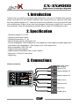
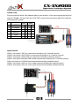
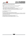
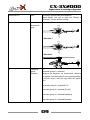
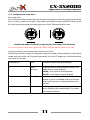
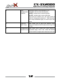
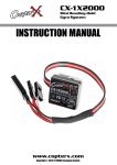
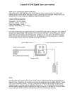
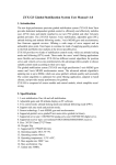
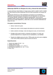
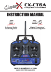
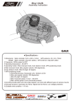
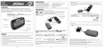
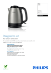
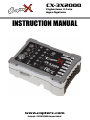
CX-3X2000
Flybarless 3 Axis
Gyro System
INSTRUCTION MANUAL
www.copterx.com
Copyright © 2013 KY MODEL Company Limited.
CX-3X2000
Flybarless 3 Axis Gyro System
MENU
1.
2.
3.
4.
5.
6.
7.
8.
9.
Table of content
Introduction
Specifications
Connections
LED Indication
Gyro Mounting
Installation of Servo Horns and Linkages
Set Parameters by using Transmitter
Check Before Flight
FAQ
01
1
2
2
2
4
5
6
7
13
14
CX-3X2000
Flybarless 3 Axis Gyro System
1. Introduction
Thank you for your purchase of CopterX high performance 3 axis gyro CX-3X2000. With compact
design, micro processor, anti vibration aluminum alloy casing, easy to use setup box, and future
firmware update available via PC. Make this one of the most advance 3 axis gyro which will work
with anything from EP100 to large scale nitro helicopter. Please keep a copy of this manual for
future reference. Enjoy the high performance flight offer by CopterX CX-3X2000 gyro system.
2. Specification
• Operating voltage: DC 3.5V-9V
• Operating current drain: 60mA
• Operating temperature: -15 ~65
• Maximal angular velocity: 800 degrees/sec
• Tail servo compatibility: 1.52ms analog servo, 1.52ms digital servo, 760us digital servo, 960us digital servo
• Swash plate servo compatibility: 1.52ms analog servo, 1.52ms digital servo
• Radio compatibility: PPM, PCM, 2.4G
• Supporting firmware upgrade
• Supporting Multi-Blade Rotor Head / Quad / Airplane
• Dimensions: 37.2mm*25.2mm*13mm
• Weight: 20g
3. Connections
Connect to receiver
Black: AUX (GAIN)
Red: Elevator
White: PITCH
Receiver Rudder CH
Receiver Aileron CH
Aileron Servo
Elevator Servo
Pitch Servo
Rudder Servo
02
CX-3X2000
Flybarless 3 Axis Gyro System
FUTABA S-BUS
Plug the short end of the S-Bus adapter cable to your receiver's S-Bus port and plug the long end
to the CX-3X2000's SYS port. Enter the "FUNCTION" menu of your transmitter, define the sequence
of the channels as below.
Mode 2
Mode 1
1
AILERON
J1
T1
J1
T1
2
ELEVAROR
J2
T2
J3
T3
3
THROTTLE
J3
T3
J2
T2
4
RUDDER
J4
T4
J4
T4
5
GYRO
-
-
-
-
6
PITCH
J3
-
J2
-
Spektrum DSM
DSM2-1: transmitter is DX7, etc. (recommend to bind by 6 or 7 channels receiver)
DSM2-2: transmitter is DX8, DSX9, etc. (recommend to bind by 6 or 7 channels receiver)
DSM2-3: transmitter is DX8, DSX9, etc. (recommend to bind by 9 channels receiver)
DSM2-4: transmitter with DM8, DM9 module (recommend to bind by 6 or 7 channels receiver)
DSMJ: transmitter is in DSMJ format (recommend to bind by matched receiver)
DSMX-1: transmitter is DX8, etc. (11ms mode, recommend to bind by matched receiver)
DSMX-2: transmitter is DX8, etc. (22ms mode, recommend to bind by matched receiver)
03
CX-3X2000
Flybarless 3 Axis Gyro System
Connect to servos
Connect the tail servo to CH4 and connect swashplate servos to CH1, CH2, CH3 according to the
type of the swashplate.
4. LED Indication
Steady Red
Gyro is in AVCS mode
Steady Blue
Gyro is in normal mode
All A/B LED flash synchronously
Gyro is not receiving signal from receiver
A/B LED flash alternatively
Gyro is initializing, keep the gyro steady, rudder,
aileron, elevator stick centered
Flashing Red
Error occur during initialization, restart gyro
04
CX-3X2000
Flybarless 3 Axis Gyro System
5. Gyro Mounting
The gyro should mount to a steady platform which is perpendicular to the main shaft and far away
from the engine and other electric devices.
Mount the gyro to the platform by using a soft foam pad, relax the cable of gyro to reduce
transmission of vibrations through the cable. Do not allow the gyro case to touch other parts of the
helicopter.
Mounting on a small electric helicopter: just use a 2-3mm foam pad.
Mounting on a large or a High vibration helicopters: use a foam pad on each side of the damping
shield plate.
There are three directions can be selected for mounting the gyro.
05
CX-3X2000
Flybarless 3 Axis Gyro System
6. Installation of Servo Horns
and Linkages
Make sure all the mechanical parts of the rotor head, the swashplate and the tail rotor are installed
correctly, all parts can move smoothly, and all the servos are installed firmly.
Mount control balls to swashplate servo horns. We recommend the distance from the ball to center
is: 12.5-13mm (250,450size), 14-14.5mm (500size), 14.5-15mm (600 or larger size).
Mount control ball to tail servo horn. We recommend the distance from the ball to center is: 4.5mm
(250size), 7.5-10mm (450, 500size),13.5-15mm(600 or larger size).
Install the horn to tail servo temporarily, adjust the horn position to make it perpendicular to the
linkage, then set the tail pitch to be approximately 8° in the direction that compensates the main
rotor torque by adjusting the linkage length.
Notice: Don’t connect servos to the gyro until finishing the servo type configuration.
06
CX-3X2000
Flybarless 3 Axis Gyro System
7. Set Parameters by using Transmitter
7.1. Transmitter configuration
Power on the transmitter and create a new helicopter model, set the trims and sub-trims of all the
channels to be zero. Set the swashplate mode as a no mixing mode (Futaba: H1; JR: 1 servo NORM)
in your transmitter. Make sure all the mixing functions related to swashplate and tail are turned off.
Do not adjust the collective pitch curve now, remain it as a straight line.
Take DX7 and 8FG for example, conservative configuration shown below.
DX7
Parameter
Path
Value
Type of gyro sensitivity adjustment
GYRO SENS
RUDD D/R
Tail sensitivity adjustment
GYRO SENS->RATE
0: 28%
1: 71%
Tail sensitivity switch
INPUT SELECT->GEAR GYRO SYS
All the channel travel adjust
TRAVEL ADJUST
100%
All the channel sub trim
SUB TRIM
0
All the channel dual rate
D/R&EXP->D/R
100%
Aileron elevator exp
D/R&EXP->EXP
+40%
Parameter
Path
Value
Gyro sensitivity in each condition and mode
Model-> Gyro Rate
35%
In each condition and
mode
All channel end point
Linkage->End Point
100
All the channel sub trim
Linkage->Sub Trim
0
All the channel dual rate
Model->Dual Rate
100
Aileron elevator exp
Model->Dual Rate-EXP -40
8FG
07
CX-3X2000
Flybarless 3 Axis Gyro System
7.2 Configuration of system menu and setup menu
There are two menus in programming mode: system menu and setup menu.
Notices:
• Always exit programming mode before attempting to fly the model.
• The items of the two menus can be called circularly.
• When complete a setup, press the SET button to save the setup and enter the next item.
• If the servo type is not selected, disconnect the servos to the gyro.
• When complete and save all the setup, restart the gyro to exit programming mode.
7.2.1 Configuration of system menu
Enter the system menu
Please make sure aileron travel and Dual Rate are set to 100%.
Turn on the transmitter, connect the gyro to receiver, power on the gyro , hold aileron stick full left
or right until the A/B led start flashing, center the stick. Now the gyro enters the system menu, press
the SET button to the first item.
Change a parameter, save the parameter and switch to next item.
Move aileron stick left or right can change a parameter;
Press the SET button can save the parameter and switch to next item.
08
CX-3X2000
Flybarless 3 Axis Gyro System
Indication LED
Item
Description of parameter and condition
(Move aileron stick left or right can Change a
parameter, *Factory default setting)
1
Installation
direction of
gyro
1: Drection 1*
2: Direction 2
3: Direction 3
2
Parameter
group
selection
1:
parameter group 1 is selected
(Beginner, for beginner we recommend selecting
this option. If the helicopter is not in good condition
or the tail servo is slow, tail wag, select this option
too)*
2:
parameter group 2 is selected(F-3C)
3:
Parameter group 3 is selected(3D soft)
4:
Parameter group 4 is selected(Hardcore)
5:
Parameter group 5 is selected(Extreme)
09
CX-3X2000
Flybarless 3 Axis Gyro System
3
Servo type
Before completing the servo type selection, don’t
connect the servo to the gyro. It may damage the
servos and gyro.
1: All the tail and swashplate servos are 1520us
analog.*
2: Tail servo is 1520us digital,
swashplate servos are 1520us analog.
3: Tail servo is 1520us digital,
swashplate servos are 1520us digital.
4: Tail servo is 760us digital,
swashplate servos are 1520us analog.
5: Tail servo is 760us digital,
swashplate servos are 1520us digital.
6: Tail servo is 960us digital,
swashplate servos are 1520us digital.
4
Swashplate
type
1: mechanical mixer
2: 120 degree CCPM*
3: 135 degree CCPM
4: 140 degree CCPM
5: 90 degree CCPM
5
Pirouette
1: positive
optimization 1: negative*
In this item, the swashplate tilts to a direction. Now
you can consider the swashplate to be a compass,
the direction of tilt is the compass orientation. Pick
up helicopter and rotate it around its main shaft for
90 degrees, check the swashplate compass
orientation, if it maintains it’s orientation, the sign of
“Pirouette optimization” is right, if it goes to the
opposite orientation, reverse the sign of “Pirouette
optimization”.
6
Data reset
Move aileron stick right and left quickly for several
times, until the blue lamp flashes fast, then all the
parameters of system menu and setup menu is reset
to the factory default settings.
10
CX-3X2000
Flybarless 3 Axis Gyro System
7.2.2 Configuration of setup menu
Enter setup menu
Turn on the transmitter, connect the gyro to receiver and connect servos to gyro(do not Install the
horns to servos), power on the gyro , hold rudder stick full left or right until A/B LED flash, center
the stick. Now the gyro enter the setup menu, press the SET button to the first item.
Rapidly hold rudder stick full left or right until the three lamps flash alternately
If you can't enter the setup menu, please set TRAVEL and Dual Rate for rudder CH to 100!
Change a parameter ,save the parameter and witch to next item
Move aileron stick left or right can Change the sequence number of the parameter in a item; Move
rudder stick left or right can Change the parameter; Press the SET button can save the parameter
and switch to next item.
Indication LED
Item
Description of parameter and condition
1
Servo
direction
Use Aileron stick to switch between 4 servos, Use
Rudder stick to switch direction.
Red LED: servo move in normal direction
Blue LED: servo move in reverse direction
2
Servo Trim
Set pitch curve to 50%, Use Aileron stick to switch
between 4 servos, Use Rudder stick to set the trim.
Adjust so all servo horns are perpendicular to the
push rod.
3
Servo Limit
Use Aileron stick to switch between 4 travel limits.
Servo will make to limit automatically. Use rudder
stick to adjust the limits.
11
CX-3X2000
Flybarless 3 Axis Gyro System
4
Use Aileron stick to swich between 3 axis.
Gyro
Compensation Use Rudder stick to select the direction.
Red LED: compensate in normal direction
Direction
Blue LED: compensate in reverse direction
Please note you need to exit the setup mode to
check for compensation direction. Check direction
after setup and before flight, or serious injury may
occure
5
Collective
pitch range
6
Compensation Move rudder stick to adjust this value, (default 0,
of pitch to tail adjustment range -40 to +40). Move the throttle
stick to check for compensation direction and travel.
Move rudder stick to adjust the collective pitch
range travel (default value 60, adjustment range -125
to +125)
12
CX-3X2000
Flybarless 3 Axis Gyro System
8. Check Before Flight
8 .1 Check before first flight
Disconnect the speed controller and motor, power on the transmitter and the helicopter, move all
the stick to check the servo direction.
Pick up helicopter and rotate it around its 3 axis, check the Gyro Compensation Direction.
Enter the system menu ,check the Pirouette optimization direction again.
yaw axis:
roll axis:
pitch axis:
13
CX-3X2000
Flybarless 3 Axis Gyro System
8.2 Check before each flight
• Always check the transmitter and receiver battery voltage to ensure they have enough remaining
capacity to complete the flight.
• Verify that the gyro is operating correctly.
• Verify that the gyro compensates in the correct direction
• Verify that the gyro is operating in the desired mode.
• Verify that the gyro mounting pads are in good condition.
• Verify that the gyro wires are not contacting the frame of the helicopter.
9. FAQ
Tail oscillate quickly(tail wag, hunting).
• Make sure the helicopter is in good mechanical condition. All shafts must absolutely straight. Limit the vibration as
low as possible. Make sure the tail rotor pushrog is straight.
• Decrease the gyro sensitivity setting on transmitter until 15%(JR:57%).
• Select parameter group 1 (F3C mode) in system menu
Helicopter swing randomly.
• Make sure the helicopter is in good mechanical condition. All shafts must absolutely straight. Limit the vibration as
low as possible.
• Use the accessory shield plate and mounting pad. A coin also is OK.
• Decrease the setting of Rsps parameter within gyro.
Rotate uncontrollable.
• Check the Installation direction of gyro
• Check the Gyro Compensation Direction
• Move all the stick to check the servo direction.
Rotate on a direction slowly and continually, drift.
Remain the airframe immobile and the aileron elevator and rudder stick centered during initialization
Red lamp keep flashing
Error occur during Initialization, restart the gyro
Helicopter unstable when fast Pirouette
Enter the system menu ,check the Pirouette optimization direction again
About gyro initialization
When power on, the gyro needs several seconds to initialize. During initialization, Remain the airframe immobile and
the aileron elevator and rudder stick centered, red yellow and blue lamps flash synchronously. When initialization
complete, the tail servo will move right and then left to indicate.
Quickly dial the gain switch between Normal Mode and AVCS Mode for several times, the gyro will initialize again
14
www.copterx.com
Copyright © 2013 KY MODEL Company Limited.