1
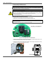
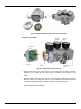
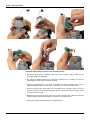
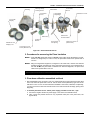
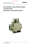
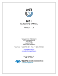
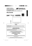
OPERATION MANUAL F Y C A L M E smar www.smar.com Specifications and information are subject to change without notice. Up-to-date address information is available on our website. web: www.smar.com/contactus.asp FYCAL – Calibration Device for Pressure Transducer Waiver of responsibility The contents of this manual abides by the hardware and software used on the current equipment version. Eventually there may occur divergencies between this manual and the equipment. The information from this document are periodically reviewed and the necessary or identified corrections will be included in the following editions. Suggestions for their improvement are welcome. Warning For more objectivity and clarity, this manual does not contain all the detailed information on the product and, in addition, it does not cover every possible mounting, operation or maintenance cases. Before installing and utilizing the equipment, check if the model of the acquired equipment complies with the technical requirements for the application. This checking is the user’s responsibility. If the user needs more information, or on the event of specific problems not specified or treated in this manual, the information should be sought from Smar. Furthermore, the user recognizes that the contents of this manual by no means modify past or present agreements, confirmation or judicial relationship, in whole or in part. All of Smar’s obligation result from the purchasing agreement signed between the parties, which includes the complete and sole valid warranty term. Contractual clauses related to the warranty are not limited nor extended by virtue of the technical information contained in this manual. Only qualified personnel are allowed to participate in the activities of mounting, electrical connection, startup and maintenance of the equipment. Qualified personnel are understood to be the persons familiar with the mounting, electrical connection, startup and operation of the equipment or other similar apparatus that are technically fit for their work. Smar provides specific training to instruct and qualify such professionals. However, each country must comply with the local safety procedures, legal provisions and regulations for the mounting and operation of electrical installations, as well as with the laws and regulations on classified areas, such as intrinsic safety, explosion proof, increased safety and instrumented safety systems, among others. The user is responsible for the incorrect or inadequate handling of equipments run with pneumatic or hydraulic pressure or, still, subject to corrosive, aggressive or combustible products, since their utilization may cause severe bodily harm and/or material damages. The field equipment referred to in this manual, when acquired for classified or hazardous areas, has its certification void when having its parts replaced or interchanged without functional and approval tests by Smar or any of Smar authorized dealers, which are the competent companies for certifying that the equipment in its entirety meets the applicable standards and regulations. The same is true when converting the equipment of a communication protocol to another. In this case, it is necessary sending the equipment to Smar or any of its authorized dealer. Moreover, the certificates are different and the user is responsible for their correct use. Always respect the instructions provided in the Manual. Smar is not responsible for any losses and/or damages resulting from the inadequate use of its equipments. It is the user’s responsibility to know and apply the safety practices in his country. 3 Table of Contents TABLE OF CONTENTS TABLE OF CONTENTS .................................................................................................................................. 4 DESCRIPTION ................................................................................................................................................ 5 PIEZO BASE ................................................................................................................................................... 6 GENERAL ......................................................................................................................................................................6 PROCEDURES TO CALIBRATE THE PIEZO BASE ....................................................................................................7 1. 2. 3. 4. 5. DISASSEMBLY FOR MAINTENANCE ............................................................................................................................... 8 PROCEDURES FOR MEASURING THE PIEZO INSULATION........................................................................................ 11 PIEZO BASE CALIBRATION ASSEMBLED ON BLOCK .................................................................................................. 11 CALIBRATION OF THE PIEZO BASE SEPARATELY IN THE FYCAL ............................................................................ 15 DISASSEMBLY OF PIEZOELECTRIC ELEMENT ............................................................................................................ 16 TECHNICAL SPECIFICATIONS ................................................................................................................... 19 FYCAL DIMENSIONAL DRAWING..............................................................................................................................19 MANOMETERS ACCURACY CLASS..........................................................................................................................20 SPARE PARTS LIST ....................................................................................................................................................20 RETURNING MATERIALS .............................................................................................................................................2 APPENDIX A - APPENDIX ......................................................................................................................... A.1 4 Description DESCRIPTION The FYCAL is a Calibration Device for Pressure Transducer – the piezo base – the part of the electro-pneumatic positioner, Smar FY. The FYCAL, therefore, is destined for Smar FY positioner users for HART® (FY301 and FY400), FOUNDATION™ fieldbus (FY302), PROFIBUS-PA (FY303) technologies. Figure 01 – FYCAL and Calibration Tool The FYCAL is a Calibration Device for Pressure Transducer, designed to calibrate the piezo base at the instrumentation workshop. Ideal for both by engineers and instrumentation technicians. Figure 02 – Calibration Tool (Detail) This instrument is the result from Smar vast experience in providing support and assistance to their customers. The Smar Pressure Transducer Calibration Device is undoubtedly one more tool to help make the user self-sufficient in Smar products maintenance. 5 FYCAL - Operation Manual PIEZO BASE General SMAR positioner, have principle of operation based on the piezoelectric element, which produces a deflection when a voltage is applied. In this positioner voltage varies of 0 to 100 Vdc. When the positioner is in the PV = SP correct position, the voltage applied to the piezo is defined as the control voltage. This is the specific position of the valve positioner, where the force that the diaphragm exerts on the spool is balanced by the spring force. The spool is in a position where there is not any air flow crossing to the outputs, and not return any air flow from the actuator chambers until the atmosphere through the positioner. This is because do not have necessity to change the actual position of the valve. It is recommended that this control voltage is as close as possible to 50 Vdc, or in the range 30 to 70 Vdc, so that we can secure a good operation of the equipment. The Base Piezo is factory calibrated, according to parameters specified above, but in the field due to factors such as vibration, poor air quality instrumentation and various environmental factors influence the calibration, where the control voltage can get out of range recommended. When this occurs it is necessary to recalibrate the piezo base. Calibration is the adjustment in the height "h", see figure below. This adjustment allows the control voltage will be approximate to the ideal value 50 Vdc. Figure 03 - Schematic of Equilibrium Position Through configurators (HART, PROFIBUS and Fieldbus), model recommended by Smar, it is possible check the voltage on the piezo, with the positioner in operation. Checking the voltage value on the piezo: • Put the setpoint to any value, 10 to 90% range, and when the valve stem stops moving, check the voltage on the piezo through the configurator. Actions based in the control voltage value analysis: • 30Vdc <Vpiezo <70Vdc: no need calibration; 6 • 20Vdc<Vpiezo<30Vdc or 70Vdc<Vpiezo<80Vdc: positioner is still working properly but indicates the need to schedule a preventive maintenance; • Vpiezo<20Vdc or Vpiezo>80Vdc: is necessary to remove the valve positioner, disassemble and calibrate the piezo base as the following. FYCAL – Calibration Device for Pressure Transducer Procedures to Calibrate the Piezo Base Figure 04 – Flowchart - Procedures to Calibrate the Piezo Base 7 FYCAL - Operation Manual 1. Disassembly for Maintenance IMPORTANT 1. Before disassemble the FY positioner check the warranty SMAR. 2. Check and evaluate if disassembly is really necessary. Refer to the User Manual, Operation and Maintenance for details on FY Positioner maintenance. WARNING AVOIDING ELECTROSTATIC DISCHARGES Electrostatic discharges may damage semiconductor electronic components in printed circuit boards. They usually occur when touching components or connector pins from plates, without wearing the appropriate equipment to prevent discharges. It is recommended to take the following precautions: Before handling positioner, remove the electrostatic charge from your body by wearing a proper wristband or touching grounded devices; Avoid touching electronic components or connector pins from plates. Removing Transducer of the Electronic Housing Depressurize the set and disconnecting wiring of the terminal block; Remove the cover with display and unscrew LCD display and main board; NOTE Be careful when reassembling the main board, location adjustment sensor is very fragile and easily can be damaged, see figure below. When assembling, make sure the board is not pressing the power cables; reed switch - Local Adjust Sensor. Exclusive to positioners of the FY300 line. Figure 05 - Local Adjust Sensor of the Main Board Disconnect the power supply cable (white connector) and the flat cable (release lockers) on the main board (see figure below), the main board is released. Release the housing rotation locking screw. Carefully rotate throughout the transducer housing to release it, be careful not to damage the flat cable; CA K E UT I EP O HOUSING ROTARY LOCKING SCREW 8 A L P EX NE E A E AP M AT M O SF E R DO ER T AD O Q U A N O RG S I I Z VA AD O O AD I D NH CU T E N MA E X P LOSI V E IN WH E N CI R C AT M T UI O N I GH T T E ER E PH V S AL I FYCAL – Calibration Device for Pressure Transducer Figure 06 - Disassembled housing with disconnected transducer Transducer Disassembly Assembled Diaphragm Pneumatic Block Connection Cover Analog Board Piezo Base Restriction Figure 07 - Disassembled connection cover Position Sensor Cover Remove the four Allen Screws of the connection cover; release it from the base very carefully, because there is a sealing ring; also, internally there is a flat cable of the hall sensor is very fragile - suggestion, you can use two screwdrivers and make a lever on opposite symmetrically sides; Remove the analog board from connection cover; the analog board is fixed only by connectors. Attention, careful not to damage the connectors in the reassembly procedure. Check that all connectors are positioned into the holes before pushing the analog board to the end; Remove the flat cable. Pull the lock (connector) that fixes the flat cable in the analog board. Check if the flat cable is not damaged; 9 FYCAL - Operation Manual Figure 08 - Disassembly connection cover and Analog Board 10 Remove the piezo base; is necessary to use a tool as for example a stylus; careful that any pointy part damage the diaphragm; See below the detailed procedures for base piezo maintenance. If necessary, see also the disassembly procedure of the piezoelectric element; Remove the diaphragm set, is necessary to separate from block pneumatic; Check that the rubber sealing joints have no cuts or holes - in this case, it is necessary to replace them; Check if the spool valve moves freely in the pneumatic block; otherwise, remove it with the spring and clean all the set with mild detergent; likewise, cleanse the inside of the block, where is housed in the spool valve; Release the four screws that fix the hall cover into the pneumatic block, need have the same careful that with the disassembly between connection cover and piezo base; Release the support of the hall sensor from hall protuberance; FYCAL – Calibration Device for Pressure Transducer Housing Housing Rotary Locking Screw Connection Cover Pneumatic Block Piezo Base Assembled Diaphragm Hall Sensor Cover Cover with Display Hall Sensor and Flat Cable Restriction Analog Board Main Boar and Display LCD Spool Valve and Spring Hall Cover Screw (M4x35 mm) Connection Cover Screw (M4x50 mm) Figure 09 – Disassembled Positioner 2. Procedures for measuring the Piezo Insulation MODE 1: Apply 100 VDC piezo base with 0 to 100 Vdc power supply and 1 uA maximum current. If there is a voltage drop of 2 volts or more, the piezo base needs to be replaced with a new one. MODE 2: Using the megohmeter equipment, configured in 100 Volts scale, measure the electrical resistance between the helmet pin of the piezo base and housing. If the measurement is less than 50 MΩ, the piezo base is insulation low. With this diagnostic, the piezo base needs to be replaced with a new one. NOTE If insulation is below this acceptable range it is necessary to replace the set base. 3. Piezo base calibration assembled on block After disassembling the connection cover, the analog board and to disconnecting the flat cable of the hall, fasten the piezo base in the set. Use the same screws (M4x35mm) type used on the hall sensor cover. It is It is recommended have available 4 new screws; otherwise, exceptionally, you may remove two screws from the hall sensor cover and use them at this stage, pinning them diagonally; To feed the piezo base use the FYCAL power supply (variable 0 to 100 Vdc, 1 μA): 1. Connect the negative terminal of power supply in the center of the metallic helmet; 2. Then connect the positive terminal on any unpainted metal part of the piezo base, see figures below; 11 FYCAL - Operation Manual Figure 10 – Assembling to supply the piezo base - using the FYCAL power supply Initially, apply 50 VDC on the piezo base. apply supply air in positioner, it is recommended to apply an approximate pressure that the positioner going to work; Figure 11 – Assembled Piezo base to use the FYCAL power supply With the FYCAL calibration tool, rotate the metal helmet, adjusting its position until the pressure in the output 1 and output 2 are minimal and equal, in this situation the piezo base is calibrated; 12 FYCAL – Calibration Device for Pressure Transducer Note 1: Note 1: The change in pressure at the two outputs can be easily noticed by the change of the sound when air flows through them. Note 2: Movement small of rotation imply in much variation in pressure at the outputs; care and sensitivity is recommended for this operation. After this calibration, change the voltage applied down and up, to confirm the proper functioning of the set. This change results in a change in pressure at the two outputs. With voltages greater than 50 VDC output 1 must be greater pressure than the output 2, and with less than 50 VDC voltage output 2 will have higher pressure compared to the output 1. NOTE If you cannot to perform the piezo base calibration on the block, it is necessary to verify the piezo base separately, mounted on the structure of the FYCAL. See item 4 - Calibration of the Piezo Base separately in the FYCAL, so that you can locate the problem. Figure 12 - Piezo Base Calibration on the block with help the Base Tool Calibration If the calibration is ok, execute steps for equipment reassembly. Remove the air pressure; Remove the fixing screws of piezo base on the block and reassemble in the hall cover; Assemble the flat cable in the analog board, and after in the connection cover – be careful when mount the analog board in the connection cover. Assemble the connection cover in the base, fix correctly the four screws. Assemble the electronic house in the transducer and reassemble the positioner on the actuator; Execute setup; 13 FYCAL - Operation Manual Input Pressure Indication Pilot Pressure Indication Pneumatic Input 4 to 20 mA Output 0 to 100 Vdc Output Display - Power Supplay Indication and Current Figure 13 - FYCAL 4. Calibration of the Piezo Base separately in the FYCAL Piezo Base Assembly Base Figure 14 – Calibration of the Piezo Base separately in the FYCAL 1. Remove the restriction and check if it is not clogged. For details see FY manual, maintenance section. 2. Put back the restriction on the piezo base. 3. Assemble the piezo base on the FYCAL, by fixing the four screws as to ensure a good tightening. 4. Connect the electric cables from FYCAL 0 to 100 V output up to the piezo base be calibrated. Observe the negative polo (black cable) be connected to base center and that positive (red cable) be fixed in any base fixation screw, according figure. NOTE The negative cable has a type needle conector for a easy conection to the piezo base center. Procedure to testing if the base is OK or NO 1. Apply 20 PSI input pressure; 2. Apply 50 Vdc to the piezo base; 14 FYCAL – Calibration Device for Pressure Transducer 3. With the help of calibration tool of the piezo base, carefully rotate the position in towards to piezo base, until the pilot pressure measured at the gauge is at about 8 PSI; 4. Apply 100 V voltage and check that the pilot pressure dropped to below 3 PSI; 5. Apply 0 V voltage and check that the pilot pressure exceeds 12 PSI. Piezo base with performance similar to the above is functioning correctly. Return and execute the calibrate procedure piezo base on the block, if not successful, the can be problem in the diaphragm or valve spool. NOTE Problems on the Diaphragm: if the diaphragm is damaged, with holes or rips, must be replaced with a new one; Problems on the spool: Generally, simply perform the cleaning procedure. In some cases, when damaged, should be replaced with a new one. If the Base Piezo is not as specified in the test above, it is necessary to disassemble for cleaning the piezoelectric element, as shown below. 5. Disassembly of Piezoelectric Element This disassembly is only recommended when it is impossible modulation between the outputs of pressure in the calibration procedures described above. This procedure is to check if is possible clean the piezo impurities or eliminate accumulated humidity during operation. Disassembly of the metallic helmet: Remove the snap ring with Circlip pliers; Remove the "helmet" set that contains the piezo, washers and spring; there is an o’ring in the set and may be have a little difficult to disassemble; Use the Circlip pliers to carefully pull the parts. Figure 15 – Removing the “helmet” that contains the piezo 15 FYCAL - Operation Manual CLEANING: Clean inside of the base with a clean cloth containing a little of neutral detergent, dry it applying dry compressed air. Carefully clean the piezo with a dry clean cloth and apply dry compressed air to remove any impurities, oil or humidity. Figure 16 - Cleaning Piezo REASSEMBLY Previously assemble the set of parts over the metal helmet in the following sequence: 1. O’ring; 2. first washer; 3. adjust spring; 4. second washer. See figure of the piezo base reassembly. 16 Insert the set of the piezo into the base cavity, making sure that the helmet guide pin is positioned in the gap of the base to fit. Make sure that the helmet rotates freely. Put the snap ring with the Circlip pliers. Make sure that the washers and spring are centralized. Press the snap ring with a screwdriver to seat it properly. Calibrate the piezo base; if not successful on the calibration, replace with a new piezo base. FYCAL – Calibration Device for Pressure Transducer Figure 17 - Reassembling of the piezo base Figure 18 – Exploded view of the assembled piezo base 17 FYCAL - Operation Manual TECHNICAL SPECIFICATIONS Power Supply 110 or 220 Vac – 50 or 60 Hz Pressure Input 0 to 100 psi Output Signals 0 to 100 Vdc input for the piezoelectric sensor (Continuous potentiometer increase) 4 to 20 mA (1µA resolution) (Continuous or Step increase through pushbutton key) The product includes: one calibration tool; a pair of cables to connect the jig to the piezo base; a pair of cables to connect the 4 to 20 mA jig output to the positioner; a regulation filter at the pressure input. FYCAL Dimensional Drawing 60 20 70 80 20 10 acros 35 40 5 45 0 100 INLET PRESSURE acros 50 PILOT PRESSURE VARIABLE STEP ADJUST Vdc ADJUST DISPLAY Vdc DEC OUTPUT 4-20mA 30 10 90 0 25 psi 15 173 (6.81) 50 psi 135 (5.31) 40 30 INC OUTPUT 0-140Vdc 1uA DISPLAY mA STEP 25% FY CAL 125 (4.92) 180 (7.08) 35 (1.38) 155 (6.10) 245 (9.65) 262 (10.31) 210 (8.27) 60 (2.36) CK LO 1 0- AR 2B 60 (2.36) SH PU 90 10 0 acros 100 90 5 0 acros 100 Figure 19 – FYCAL Dimensional Drawing 18 FYCAL – Calibration Device for Pressure Transducer Manometers Accuracy Class Below the FYCAL manometers accuracy class: ABNT (B Class) ± 2,0% (F.S.) between 25% and 75% of the range, ± 3,0% (F.S.) the remainder of the range. Spare Parts List SPARE PARTS LIST PARTS DESCRIPTION CODE Accuracy potentiometer - FYCAL 400-1172 Electronic circuit board – FYCAL 400-0906 Pressure regulator 400-1181 Power supply cable for 4 to 20 mA 400-1182 Power supply cable for 0 to 100 V 400-1183 Tool for transducer calibration, new version 400-1185 Sealing joint 400-1186 19 Appendix A SRF – Service Request Form FYCAL – Calibration Device for Pressure Transducer GENERAL DATA Serial Number: _______________________________________________________________________________________________ SITUATION DESCRIPTION ______________________________________________________________________________________________________________ ______________________________________________________________________________________________________________ ______________________________________________________________________________________________________________ ______________________________________________________________________________________________________________ ______________________________________________________________________________________________________________ ______________________________________________________________________________________________________________ ______________________________________________________________________________________________________________ ______________________________________________________________________________________________________________ ______________________________________________________________________________________________________________ ______________________________________________________________________________________________________________ ______________________________________________________________________________________________________________ ______________________________________________________________________________________________________________ ______________________________________________________________________________________________________________ ______________________________________________________________________________________________________________ ______________________________________________________________________________________________________________ ______________________________________________________________________________________________________________ ______________________________________________________________________________________________________________ ______________________________________________________________________________________________________________ ______________________________________________________________________________________________________________ ______________________________________________________________________________________________________________ SERVICE SUGGESTION Adjustment ( ) Cleaning ( ) Preventive Maintenance ( ) Update / Up-grade ( ) Other: _________________________________________________________________________________________________________ USER INFORMATION Company: _____________________________________________________________________________________________________ Contact: ______________________________________________________________________________________________________ Title: _________________________________________________________________________________________________________ Section: _______________________________________________________________________________________________________ Phone: _________ _________________________ _________ _________________________ Extension: ____________________ E-mail: _________________________________________________________________________ Date: ______/ ______/ __________ For warranty or non-warranty repair, please contact your representative. Further information about address and contacts can be found on www.smar.com/contactus.asp. A.1 FYCAL - Operation Manual Returning Materials If necessary to return the device and/or configurator to SMAR, simply contact our office, informing the defective instrument serial number, and return it to our factory. In order to speed up analysis and solution of the problem, the defective item should be returned with a description of the failure observed, with as much details as possible. Other information concerning the instrument operation, such as service and process conditions, is also helpful. Instruments returned or to be revised outside the guarantee term should be accompanied by a purchase order or a quote request. A.2