1
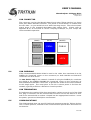
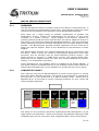
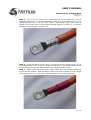
USER'S MANUAL WaveSculptor 22 Motor Drive TRI88.004 ver 2 18 April 2012 WaveSculptor 22 Motor Drive User's Manual 18 April 2012 ©2012 Tritium Pty Ltd Brisbane, Australia http://www.tritium.com.au 1 of 35 USER'S MANUAL WaveSculptor 22 Motor Drive TRI88.004 ver 2 18 April 2012 TABLE OF CONTENTS 1 Introduction........................................................................................4 2 Getting Started...................................................................................5 3 Unpacking & Preparation.....................................................................5 4 4.1 4.2 Controller Function.............................................................................6 Overview............................................................................................................... 6 A Note on Motor and Battery Currents...................................................................6 5 5.1 5.2 5.3 5.4 Mounting............................................................................................6 Choosing A Location.............................................................................................. 6 Environmental....................................................................................................... 6 Heatsinking........................................................................................................... 6 Cable Positioning................................................................................................... 7 6 6.1 6.2 Accessing the Controller......................................................................7 Safety.................................................................................................................... 7 Inspection Cover.................................................................................................... 7 7 7.1 7.2 7.3 7.4 Cooling...............................................................................................8 Overview............................................................................................................... 8 Efficiency............................................................................................................... 8 Heatsink Requirements........................................................................................ 10 Mechanical interface............................................................................................ 11 8 8.1 8.2 8.3 8.4 8.5 8.6 8.7 8.8 8.9 8.10 CAN Bus and Low Voltage..................................................................12 CAN Network Topology......................................................................................... 12 CAN Wiring.......................................................................................................... 12 CAN Connector.................................................................................................... 13 CAN Shielding...................................................................................................... 13 CAN Termination.................................................................................................. 13 Communications.................................................................................................. 13 Power Supply....................................................................................................... 14 Driver Controls..................................................................................................... 14 System Expansion............................................................................................... 14 Multiple Motors.................................................................................................... 14 9 9.1 9.2 9.3 PC Software......................................................................................15 Ethernet Bridge Installation.................................................................................15 PC Software......................................................................................................... 15 Low Voltage & CAN Bus Testing...........................................................................15 10 Driver Controls..................................................................................15 11 11.1 Motor Sense Connections..................................................................16 Overview............................................................................................................. 16 2 of 35 USER'S MANUAL WaveSculptor 22 Motor Drive TRI88.004 ver 2 18 April 2012 11.2 11.3 11.4 Connector Pinout................................................................................................. 16 Motor Position Sense........................................................................................... 17 Motor Temperature Sense....................................................................................17 12 12.1 12.2 12.3 12.4 12.5 12.6 12.7 High Power Connections....................................................................17 Cable................................................................................................................... 18 Motor Inductance................................................................................................. 18 High Power Connections......................................................................................18 Testing................................................................................................................. 19 Precharge............................................................................................................ 19 Fusing.................................................................................................................. 19 HV Isolation......................................................................................................... 19 13 13.1 13.2 13.3 13.4 Motor Setup & Testing.......................................................................20 Low Power Setup................................................................................................. 20 PhasorSense – BLDC Motors................................................................................20 Low Power Testing – PC Control............................................................................20 Low Power Testing – Driver Controls Hardware.....................................................21 14 14.1 14.2 14.3 High Power Testing............................................................................21 Connections......................................................................................................... 21 PC Software Control ............................................................................................ 22 Driver Controls..................................................................................................... 22 15 15.1 15.2 15.3 Driving............................................................................................. 22 Warnings.............................................................................................................. 22 Procedure............................................................................................................ 22 On Road Testing................................................................................................... 23 16 16.1 16.2 Appendix A – Recommended Component Sources................................24 CAN cabling & Low Voltage Connectors...............................................................24 High power cabling & Connectors........................................................................24 17 17.1 17.2 Appendix B – Guide to Successful Crimping.........................................25 Molex MicroFit 3.0................................................................................................ 25 High Power Bolt Lugs........................................................................................... 25 18 18.1 18.2 18.3 18.4 18.5 Appendix C – CAN Communications Protocol.......................................28 Overview............................................................................................................. 28 Drive Commands................................................................................................. 29 Drive Command Examples...................................................................................30 Motor Controller Broadcast Messages..................................................................30 Configuration Commands....................................................................................34 19 Revision Record................................................................................35 3 of 35 USER'S MANUAL WaveSculptor 22 Motor Drive TRI88.004 ver 2 18 April 2012 1 INTRODUCTION This document describes the operation, connections, mounting, communications, cooling, and how to get started with and use the Tritium WaveSculptor 22 Motor Controller. This product processes and uses potentially lethal voltages and currents. Do not provide power or operate with the cover removed. To be opened and connected to by authorised personnel only. 4 of 35 USER'S MANUAL WaveSculptor 22 Motor Drive TRI88.004 ver 2 18 April 2012 2 GETTING STARTED Work through this manual in sequence, using this checklist as you go. [ ] Items arrived in good condition [ ] Read and understood the datasheet [ ] Read and understood this document [ ] A good mounting location chosen [ ] Cooling system designed [ ] Controller mounted into place [ ] CAN Bus & 12V supply wiring installed [ ] PC software installed [ ] 12V supply and CAN communications functioning [ ] Motor sense connections completed [ ] Motor phase cables connected [ ] Precharge system working [ ] HV DC cables connected [ ] PhasorSense routines run and saved [ ] Motor test at low voltage, wheels off ground, using PC software [ ] Motor test at low voltage, wheels off ground, using driver controls hardware [ ] Motor test at high voltage, wheels off ground, using PC software [ ] Motor test at high voltage, wheels off ground, using driver controls hardware [ ] Private road test [ ] On-road vehicle test 3 UNPACKING & PREPARATION Check that all items on the packing list are in the box and undamaged. Contact the shipping company and Tritium if there is obvious outer box damage during transport. Contact Tritium immediately if there is a discrepancy with the items or other damage. You will require the following specialised tools for installing the WaveSculptor motor controller: • Allen (hex) keys • Molex MicroFit crimp tool • Cable cutters • Hex lug or hydraulic crimp tool • Various electronics hand tools for low power cable cutting & stripping 5 of 35 USER'S MANUAL WaveSculptor 22 Motor Drive TRI88.004 ver 2 18 April 2012 4 CONTROLLER FUNCTION 4.1 OVERVIEW As a high-level description, the WaveSculptor takes high voltage DC from a battery pack, and converts it to a lower voltage 3-phase AC to drive a motor. Power flow is bi-directional, so it can also perform regenerative braking (regen) where power flows from the motor back into the batteries. It is a four-quadrant device, which means that it can drive or regen in both forwards and reverse directions. Ignoring the losses in the system (refer to the datasheet for efficiency curves for the WaveSculptor), total power through the motor controller is conserved. It does not create energy, it just converts it from one form (DC) to another (AC). 4.2 A NOTE ON MOTOR AND BATTERY CURRENTS Motor current is proportional to torque, whereas battery current is proportional to power. Power = Torque x speed. The effect of this is that battery current will only approach motor current as the motor speed approaches 100%. At low motor speeds, the battery current will also be low, regardless of what the motor current is. This applies to most motor controllers, but with DC motor systems (where efficiency is much more variable) the effect is not usually as noticeable. So, when reading this document (and the datasheet) make sure to note if the specification is talking about motor current or battery current. They are very different quantities. 5 MOUNTING 5.1 CHOOSING A LOCATION Careful attention should be paid to positioning the WaveSculptor correctly, to ensure optimum performance. The main criteria for choosing a good mounting location are environment, heatsinking, and cable positioning. The WaveSculptor may be mounted in any orientation including upside-down. Tool access (2mm hex key) is required at both ends of the motor controller to be able to remove the lid and make the high power bolt connections. 5.2 ENVIRONMENTAL The WaveSculptor is not rated to withstand water spray or drips. Mount it in a dry location. A good location will probably also have some ambient airflow, to help with heatsinking. 5.3 HEATSINKING The WaveSculptor22 does not contain any internal fans or active cooling components. For most uses, external cooling will have to be provided. Refer to the Cooling chapter later in this document for details. 6 of 35 USER'S MANUAL WaveSculptor 22 Motor Drive TRI88.004 ver 2 18 April 2012 5.4 CABLE POSITIONING The WaveSculptor has been designed with all cables and connections to the device at the front edge, to allow simplified positioning in your vehicle. The DC bus and motor phase cables can be quite stiff, make sure to allow enough room in front of the controller so that they can bend at greater than minimum radius. 6 ACCESSING THE CONTROLLER 6.1 SAFETY Opening the cover on the WaveSculptor will expose the high power terminals for battery and motor phase connections. High voltages may be present inside this cover. Before opening, make sure that the battery contactors are dis-engaged, so that high voltage is not present at the motor controller. Allow one minute for the internal capacitors to discharge before working on the controller. 6.2 INSPECTION COVER The lid of the controller is held closed against the base with stainless steel M3 button hex head screws, two at each end of the controller. Use a 2mm allen (hex) key to loosen and remove all four screws. Lift off the lid and set it aside. Use a multimeter to check across the battery connection terminals for high voltage. If more than a few volts are present, wait additional time for the capacitors to discharge to a safe level. To avoid damage due to static discharge, touch the controller body before working inside the controller and touching any internal circuit boards. Be extremely careful to not drop loose fasteners into the motor controller, as they may move around while driving and short out the battery or motor phase connections. When finished working inside the WaveSculptor, replace the lid and insert and tighten all four screws. 7 of 35 USER'S MANUAL WaveSculptor 22 Motor Drive TRI88.004 ver 2 18 April 2012 7 COOLING 7.1 OVERVIEW The WaveSculptor22 will usually require some form of external heatsinking. The extent of this will depend on the ambient operating temperature, the motor current and duty cycle, and operating voltage. Once these are known, the heat that is required to be removed from the controller can be calculated from its efficiency. There will be a wide variety of possible cooling solutions, which is why the WaveSculptor22 has been designed for technically qualified users to choose their own optimal solution for their exact vehicle and use scenario. The aim of the cooling solution provided by the end user is to keep the WaveSculptor cold plate temperature below the limit specified in the datasheet. Above this point, the motor controller will automatically reduce the motor output current to protect itself, resulting in reduced performance for your vehicle. 7.2 EFFICIENCY 7.2.1 Background The power electronic switching devices in the WaveSculptor22 are MOSFETs, and the majority of loss in the motor controller comes from these devices. Losses in a MOSFET are split into conduction and switching loss. Conduction loss is easy to characterise and model, but there are many MOSFET switching mechanisms that create loss. To simplify analysis, and covering the bulk of the loss in any case, this summary considers the four major switching loss types: off switching, on switching, reverse recovery, and capacitive switching loss. All of these losses have a very strong relationship to input voltage and output current, and only a weak relationship (via ripple current) to output voltage. This is an extremely useful observation for those wanting to produce a simple model of the losses in a MOSFET based motor controller. 7.2.2 Test Methodology To produce the efficiency curves in the datasheet, and the modelling information in this document, the switching losses in the WaveSculptor were measured directly, by analysing the current and voltage switching waveforms. Conduction losses were simply derived from the measured phase to phase resistance of the WaveSculptor. A high bandwidth system was used to acquire the switching waveforms, and data showing switching loss versus load current was then extracted. Semiconductor parameters were then calculated from this data, producing best fit curves and hence functions that can be used to create an efficiency map over the entire operating area of the controller. 8 of 35 USER'S MANUAL WaveSculptor 22 Motor Drive TRI88.004 ver 2 18 April 2012 7.2.3 Power Loss The power loss of the WaveScuptor22 operating with 160V DC bus voltage is shown in the diagram below: WaveSculptor22 expected power loss versus motor current 180 160 Measured loss Capacitive switching loss Switching loss (inc RR) Conduction loss 140 Power loss (W) 120 100 80 60 40 20 0 0 7.2.4 10 20 30 40 50 60 Motor Current (Arms) 70 80 90 100 Predicting Loss To allow solar racing teams to predict the WaveSculptor power loss, both for heatsink calculations and for race strategy algorithms, the following estimate of controller losses can be used: Ploss =Req I 2o I o V bus Cf eq V 2bus where I o is the output current of the controller in Arms V bus is the bus voltage (battery voltage) of the controller Req is the equivalent resistance of the entire controller is the linear component of the switching loss (per unit of bus voltage) is the constant component of the switching loss (per unit of bus voltage) Cf eq is the equivalent capacitance*frequency product of the entire controller 9 of 35 USER'S MANUAL WaveSculptor 22 Motor Drive TRI88.004 ver 2 18 April 2012 The table below gives the constants for WaveSculptor22: Constant 7.3 WaveSculptor22 MOSFETs Req 1.0800E-2 3.3450E-3 1.8153E-2 C eq 1.5625E-4 HEATSINK REQUIREMENTS Once the total motor controller loss can be calculated, an expected motor current and duty cycle is required to be able to calculate the heatsinking requirements of the controller. This will depend on such things as the mass of the vehicle, rolling and aero resistance, and expected speeds and accelerations. The more accurately this information is known, the more optimal the heatsink can be. Two scenarios are outlined below: the continuous use case; and the short term peak power case. 7.3.1 Continuous Use Say your vehicle uses a 160V DC bus, and requires 30A motor current continuously to maintain cruising speed on the highway. The ambient temperature is high, at 40°C, and the maximum cold plate temperature specified in the datasheet is 70°C – please check the datasheet for the correct value. The graph above shows that at this voltage and current, the motor controller will be producing around 35W of loss. To maintain the cold plate of the motor controller at or below the specified temperature, a cooling solution with a total thermal resistance to ambient of at least (70° – 40°) / 35W = 0.85°C/W is required. Assuming 0.05°C/W for thermal grease between the cold plate and heatsink, this means that a heatsink with a thermal resistance of at least 0.80°C/W is required. This could be provided using an off-the-shelf comb section extruded aluminium heatsink with base dimensions approximately the same as the cold plate, and a 40mm fin depth, weighing around 1.5kg, using convection airflow only. However, significant weight savings are possible by using a smaller fin depth, and force cooling with a fan. Careful placement of the motor controller in the vehicle so that there is ambient airflow could mean that the fan is not required to run continuously, therefore saving considerable power. Further improved alternatives are also available, requiring more integration with the vehicle. An example would be an aluminium plate laminated into the skin of the vehicle, such that the outside is flush with the rest of the skin (to avoid turbulence), and having the motor controller fastened to the inside surface. A plate of at least 2mm thick means that standard hex drive countersunk M4 screws can be used to fasten to the WaveSculptor, and remain flush with the outside surface. The size of this plate can be chosen to give the required thermal resistance, with heat rejected directly to ambient air outside, flowing past at 10 of 35 USER'S MANUAL WaveSculptor 22 Motor Drive TRI88.004 ver 2 18 April 2012 vehicle speed. A solution like this can provide a very low mass cooling method. Note that the above calculations are the minimum requirement. Allowance should be made for higher than expected ambient temperatures, higher than expected power use, and an amount of thermal headroom before the motor controller's thermal protection activates. 7.3.2 Short Term Peak Power Use As a further example, say that your vehicle uses a 160V DC bus, and requires 80A motor current for two minutes to do a fast qualifying time. The graph above shows that the motor controller will be producing around 120W of loss at this power level. Ambient temperature is high, at 40°C, and the maximum cold plate temperature specified in the datasheet is 70°C – please check the datasheet for the correct value. Assume that the vehicle begins the qualifying lap with a heatsink at ambient temperature. Heat from the controller in this type of scenario could possibly be stored, rather than immediately rejected to ambient. In the situation above, the total energy required to be adsorbed by the heatsink is 120W * 120 seconds = 14.4kJ. Using an aluminium block (specific heat = 0.897J/g°C) and a 30°C temperature rise would require a mass of m = Q/∆T.c =14.4kJ/30°C*0.897 = 535g. Using a thin aluminium case containing water (specific heat = 4.186J/g°C, almost 5x better than aluminium) would reduce this mass to 115g. Combining this type of heat storage device with the continuous use heatsink to ambient air will result in a cooling solution suitable both for constant lower power operation, and with the heat capacity to absorb peaks of high current operation. A combined system could be made with an all aluminium system, with a ~535g block mounted into the skin of the vehicle. This provides a low-risk option. Alternatively, other types of system such as one using a small volume of circulating water are possible, with the water providing both heat transport from the motor controller to an ambient cooling plate in the skin of the car, and also thermal mass to absorb short term high power use. 7.4 MECHANICAL INTERFACE The WaveSculptor22 provides a large flat surface to attach to your cooling solution. Refer to the mechanical drawing available on the WaveSculptor22 page on the Tritium website for dimensions and details. Use a thin layer of thermal grease or conformable thermal gap filler pad to fill any air gaps between the WaveSculptor22 cold plate and your heatsink, and provide the best thermal path between the two. This material is not required to be electrically insulating. Attach the heatsink to the cold plate using eight M4 screws threading into the tapped inserts in the motor controller base, making certain to note the maximum screw depth specified in the datasheet. Exceeding this depth will force the screw into internal components of the motor controller, almost certainly damaging it. 11 of 35 USER'S MANUAL WaveSculptor 22 Motor Drive TRI88.004 ver 2 18 April 2012 8 CAN BUS AND LOW VOLTAGE 8.1 CAN NETWORK TOPOLOGY The CAN bus is structured as a linear network, with short stubs branching from 'T' connectors on the main bus backbone to each device. The CAN bus data lines must be terminated at each end of the main bus with 120 ohm resistors between the CAN-H and CAN-L signals. In the range of Tritium EV products, including the WaveSculptor 22, EV Driver Controls, and BMS Pack Master, the CAN connections are implemented with an 'in' and an 'out' connector, therefore placing the 'T' on the device, resulting in a very short fixed-length stub on the circuit board of each device. This is ideal from a signal integrity and network performance point of view. The WaveSculptor motor controller uses the CAN bus to receive commands and transmit telemetry, as well as to provide low-voltage DC power to operate the controller electronics. Therefore, a basic system consists of three major components: 1. WaveSculptor motor controller 2. Driver controls interface to pedals, switches & gauges 3. Power supply (nominally 12V DC) to operate the system Other components can also be added to the network. Items typically found in a solar electric vehicle would include: 4. LCD and other driver information displays 5. Battery management system 6. Multiple motor controllers 7. Datalogging and RF telemetry 8.2 CAN WIRING The CAN data lines (CAN-H and CAN-L) must be implemented with twisted-pair wire for proper data integrity. The wire should have a characteristic impedance of 120 ohms. Power should also be provided along the CAN cable, ideally with another twisted pair to minimise noise pickup. An overall shield can also be advantageous. From a performance perspective, the optimal choice of cable is 7mm Devicenet CANbus 'thin' cable, with 24AWG (data) + 22AWG (power) twisted pairs and a braided shield. Using this cable will result in a robust installation. 12 of 35 USER'S MANUAL WaveSculptor 22 Motor Drive TRI88.004 ver 2 18 April 2012 8.3 CAN CONNECTOR The connector used on the WaveSculptor22 and other Tritium devices is a 6-way 3mm pitch Molex MicroFit connector. The pinout is shown below, as viewed from the wire side – as you would look at it while inserting crimps. The colours shown match those in the standard DeviceNet CAN cabling pairs. Please refer to Appendix B for an overview of correct crimping technique, as poor crimps will cause unreliable operation. 8.4 (BARE) (BLUE) (WHITE) SHIELD GROUND CAN-L CAN-H SHIELD GROUND +12V (BARE) (BLACK) (RED) CAN SHIELDING If the recommended braided shield is used in the cable, then terminate it to the SHIELD pin (lower-left corner on the connector) on both CAN IN and CAN OUT connectors on each device. On one device only in the network, instead of using the SHIELD pin, terminate the shield to the SHIELD GROUND pin (upper-left corner on the connector) on both CAN IN and CAN OUT connectors, to ground the shield for the entire network at this single point. The usual place to do this is where power is fed into the network, typically at Tritium's EV Driver Controls product. 8.5 CAN TERMINATION To implement the required 120 Ohm termination resistor at each end of the CAN bus, plug a connector into the unused CAN connector on the last device at each end of the network with a resistor crimped into the appropriate locations. Leave the power, ground and shield pins unconnected. 8.6 COMMUNICATIONS The CAN standard does not specify high-level message protocols. Tritium devices use a custom protocol, outlined in the communication specification document for each device. 13 of 35 USER'S MANUAL WaveSculptor 22 Motor Drive TRI88.004 ver 2 18 April 2012 By default, each device operates at 500 kbits/second, one step below the maximum possible data rate of 1 Mbit/second, and comes programmed from the factory with a CAN base address that will allow it to work without problems with other Tritium devices. Using the Windows PC interface program and the Tritium CAN-Ethernet bridge, both the data rate and the base address can be programmed to suit your network. WaveSculptor controllers also have a second programmable base address that they watch for command messages. This should be set to whatever base address is used by the driver controls node on the network. The WaveSculptor motor controller expects regular messages from the driver controls device. If a message is not received within a set timeout period (refer to the communications specification in Appendix A for the exact value) then the controller will change to a safe mode and will stop driving the motor until a valid message is received again. This protects against faults where either a connector is loose or broken, the cable has been damaged, or the driver controls have failed. 8.7 POWER SUPPLY Each Tritium device expects a DC supply on the CAN bus connection of between 9 and 15V. 13.8V from a small lead-acid battery charged by your vehicle's DC/DC converter is ideal. Refer to each device’s datasheet for CAN bus current consumption values, and make sure that the total is less than the rating on your chosen cable. Tritium's EV Driver Controls product provides a means to connect power from the battery into the CAN bus, to power other devices on the network. It can switch power to the CAN bus based on the state of the ignition key. 8.8 DRIVER CONTROLS Tritium can provide a CAN bus driver controls device. This interfaces to pedals and switches, and provides the messages required to operate a WaveSculptor controller. The firmware for this device is open-source, allowing it to be easily customized to suit your vehicle. As the communications specification is open, the WaveSculptor can also be operated from custom driver controls hardware specific to your vehicle, or from a Windows PC running either the provided Tritium software, or custom software of your choice. Please refer to the driver controls datasheet and user's manual on our website for further details. 8.9 SYSTEM EXPANSION Tritium can provide a CAN bus LCD display capable of showing up to four different telemetry values (one at a time) on a 3.5 digit sunlight-readable screen. Multiple displays can be used if desired. 8.10 MULTIPLE MOTORS Multiple motors/controllers are accommodated easily with the CAN bus system. All that is required is for each WaveSculptor controller to be programmed to receive messages from the same driver controls base address, and then to run 14 of 35 USER'S MANUAL WaveSculptor 22 Motor Drive TRI88.004 ver 2 18 April 2012 the vehicle in current-control mode (the default setup). Each motor will now operate at the same current, thus giving automatic wheel speed differences for cornering, with the system acting as an electronic differential. The base address of each WaveSculptor controller should be programmed to a different value. This allows viewing of separate telemetry data from each controller on the LCD displays or other telemetry systems in the vehicle. 9 PC SOFTWARE 9.1 ETHERNET BRIDGE INSTALLATION Refer to the CAN-Ethernet bridge User's Manual for installation and setup of this piece of hardware. Connect the Ethernet bridge via a CAN bus cable to the WaveSculptor. Use 120 ohm termination resistors between the CAN-H and CAN-L lines at both items. 9.2 PC SOFTWARE Refer to the Software Download section on the WaveSculptor 22 product page for the Configuration & Setup software tool download. Refer to the instructions. 9.3 Software User's Manual for installation and usage LOW VOLTAGE & CAN BUS TESTING Provide 12V DC to the CAN bus adapter at the CAN-Ethernet Bridge, to power up both the Ethernet Bridge and the WaveSculptor control electronics. If everything is connected correctly, you should see telemetry values appearing and updating several times per second in the PC software window. 10 DRIVER CONTROLS Wire and install the hardware driver controls as described in the Driver Controls User's Manual. Test the driver controls as described in the User's Manual. 15 of 35 USER'S MANUAL WaveSculptor 22 Motor Drive TRI88.004 ver 2 18 April 2012 11 MOTOR SENSE CONNECTIONS 11.1 OVERVIEW The WaveSculptor22 requires a position sensor to be able to control the motor. It can also measure the temperature of the motor, and gradually reduce the motor current if this temperature rises towards a user-programmable threshold. Since there are a large variety of possible combinations of position and temperature sensors, Tritium has implemented the interface on the motor controller in a generic manner. Small adapter circuit boards, suitable for mounting directly inside the motor terminal box, are used to adapt the sensors in that motor to the interface required by the WaveSculptor22. This also provides a robust signalling mechanism (isolated, differential) for the longest length of cable possible. The WaveSculptor provides isolated, regulated +5V and +12V DC to power the external adapter. Refer to the datasheet for specifications on these supplies. The WaveSculptor provides four isolated differential inputs for information from the motor. Three of these are routed to timer/capture peripherals in the main processor, and are normally used for three Hall-effect position sensors. The fourth channel is routed to a UART serial receiver, and expects digital data. Depending on the adapter board, this data may contain temperature, position, velocity, or a combination of all three. A brief datasheet for each adapter option is available on the Tritium website. If your motor requires an adapter that is not yet available, please contact Tritium to enquire about development, as new adapters are simple and low-cost to design. 11.2 CONNECTOR PINOUT The connector used on the WaveSculptor22 for motor sense signals is a 14-way 3mm pitch Molex MicroFit connector. The pinout is shown below, as viewed from the wire side – as you would look at it while inserting crimps. Please refer to Appendix B for an overview of correct crimping technique, as poor crimps will cause unreliable operation. SHIELD GROUND GROUND H1/A RX– H2/B RX– H3/I RX– SERIAL RX– +5V OUT +12V OUT H1/A RX+ H2/B RX+ H3/I RX+ SERIAL RX+ (RED) (YELLOW) (BROWN) (GREEN) (WHITE) (BLUE) The wiring for this connector should be implemented with twisted pairs, as the signal inputs are differential. Tritium recommends using Belden 9506 type cable (shielded 6 pair) for this connection, with suggested cable colours shown above. 16 of 35 USER'S MANUAL WaveSculptor 22 Motor Drive TRI88.004 ver 2 18 April 2012 11.3 MOTOR POSITION SENSE For operating Brushless DC (BLDC) and Permanent Magnet Synchronous (PMSM) type motors, the WaveSculptor requires three motor position sensing inputs, commonly provided using Hall-effect switches embedded in the motor. Please note that the relation between each Hall-effect input and a motor output phase, as well as the polarity of the Hall-effect input signal, does not matter. The WaveSculptor will detect these relationships when running its initial setup and configuration routine (PhasorSense). The only requirement for these signals is that they have a fixed alignment (ideally, a 0° offset) with the zero-crossing point of the back-EMF waveform of the motor, and that the signals are offset from each other by 120°. This is where most motors will be configured by default. Use an oscilloscope to check that this angle is close to 0° for your motor. 11.4 MOTOR TEMPERATURE SENSE Tritium's motor adapters are currently available for use with NTC thermistor and Pt100 temperature sensor elements. Variations are possible to accommodate thermocouple and LM35-type semiconductor sensors also. 12 HIGH POWER CONNECTIONS It is important to correctly terminate the high power wiring for successful longterm operation of the controller. DC battery and AC motor phase connections should be crimped to bolt lug crimp terminals. The bolts in the WaveSculptor22 have a metric M6 thread, so use a lug designed for this size bolt, with a 6.5mm hole. High power connections should not be soldered for vehicle applications, as the solder wicks up inside the copper strands and creates a stress point, which can fatigue and break due to the vibration present in a vehicle. For a guide to good quality crimping of the high power connections, please read Appendix B of this document. Copper oxidation is a threat to the long-term reliability of both the crimp and the bolted joint to the controller. Use a thin smear of anti-oxidation electrical jointing compound on the contact surface of the crimp lug when bolting the cable to the controller, as shown in the diagram below. Crimp Lug Cable M6 brass bolt (captive) M6 nut (full depth) M6 spring washer M6 flat washer Jointing compound layer PCB The bolts are permanently assembled into the motor controller, and are 17 of 35 USER'S MANUAL WaveSculptor 22 Motor Drive TRI88.004 ver 2 18 April 2012 prevented from rotating by a nylon holder. To assemble the bolted joint follow these steps: 12.1 • Route the cable in through the rubber grommet and locate the crimp lug down over the stud. It is easiest to push the cable through with the lug vertical, and rotate it down over the top of the bolt. • Place a plain washer on top of the lug • Place a spring washer on top of the lug • Thread a nut over the stud • Use a torque wrench to tighten the nut to 10Nm (7.5 ft.lbs) CABLE The cable used to connect to the high power terminals must be rated for the full DC battery voltage as a minimum. The current rating of the cable will depend on your expected load and duty cycle for your driving habits in your vehicle. The WaveSculptor bolt terminal area is designed to accept up to 16mm² cable with an outside diameter of up to 10mm. Tritium suggests the use of at least 110°C rated PVC cable (note that standard PVC is 90°C rated) to allow a longer duration of peak power output without exceeding the cable temperature rating – this may allow the use of a smaller cross-section cable, saving some weight. The cable should have orange coloured insulation. This is required by the NCOP14 standard for EV conversions in Australia, but is a good idea in any case. This is what is used in the Prius and other hybrid vehicles, and emergency response personnel are trained to not cut through orange cables. Use a short piece of red or black insulation at the ends of the orange cable to indicate polarity. Use of flexible cable with a high number of fine strands is advised, to help with cable routing and reduce strain and fatigue on the terminations. Tritium recommends using “ZDFX” double-insulated 0.6/1kV 110°C rated cable from Tycab Australia, which is made with a high number of 0.2mm strands, resulting in a flexible cable. It is available in orange insulation. Similar cable will be available from alternative suppliers in other countries. 12.2 MOTOR INDUCTANCE The WaveSculptor requires a minimum of 50µH inductance (phase – neutral) per phase to operate correctly. Please ensure that sufficient external inductance has been added if your motor does not have at least this amount of inductance already. External inductors will most likely only be required on ultra-high efficiency ironless BLDC type motors. These external inductors must be rated to the full motor current and have windings insulated to the full DC bus voltage. 12.3 HIGH POWER CONNECTIONS The positions of the various connections are shown on the front panel of the controller, and also labelled next to the bolt terminal on the PCB. Make certain that the DC+ and DC– connections are the correct polarity. 18 of 35 USER'S MANUAL WaveSculptor 22 Motor Drive TRI88.004 ver 2 18 April 2012 12.4 TESTING At this point, do not connect the other end of the high power DC NEG and DC POS cables to your precharge circuit or batteries. You will need to connect them to a low-voltage supply of power for initial testing, which is detailed in the “Motor Setup & Testing” section of this document. 12.5 PRECHARGE The WaveSculptor22 has 270µF of extremely low-impedance capacitance across the DC bus input connections. An external precharge circuit is mandatory. When not driving a motor, the WaveSculptor draws minimal power from the DC bus, with only a high-value discharge resistor to bleed charge. Therefore, careful attention should be given when working on the controller to ensure that the capacitors have been discharged first. Note that these capacitors hold around 3 Joules of energy and take around one minute to discharge to safe levels. Tritium can provide a circuit to implement the precharge function, as part of our Pack-Master BMS system. Please refer to the product webpage for more information. There are a variety of other ways to implement precharge but many do not automatically check for faults and may overheat themselves in the event of a problem. 12.6 FUSING At least one appropriately rated fuse must be installed in the high voltage DC circuit. This fuse must be rated to the highest expected DC voltage. AC rated fuses are not appropriate, unless they have a DC rating as well. Choosing the current rating of the fuse depends on your expected load, the maximum fault current in the battery system, duration of loads, cable sizes, and several other factors. It is beyond the scope of this document to detail fuse selection for your vehicle. Note that the WaveSculptor can be programmed to limit the current it draws from the DC bus connection, which may simplify fuse, contactor and wiring selection. However, this will also have the effect of limiting total system power throughput, so be aware that when setting it to less than 100% that you may compromise your vehicle performance. 12.7 HV ISOLATION The WaveSculptor has an isolation barrier rated to 1kV continuously between the CAN bus, the DC bus, and the Motor position connection. This helps minimise damage in the event of a fault, and also allows safe connection of the high voltage battery pack. Tritium recommends that the CAN bus be operated at the system ground potential, with CAN Ground connected to the vehicle chassis at some point in your system. The battery ground, high-voltage DC connections, and motor phases should be isolated from the vehicle chassis. This is so that a single fault anywhere in the high voltage system will not result in a high voltage potential being present between any wiring and the chassis of the vehicle. Please refer to any relevant regulations governing this type of connection. 19 of 35 USER'S MANUAL WaveSculptor 22 Motor Drive TRI88.004 ver 2 18 April 2012 13 MOTOR SETUP & TESTING 13.1 LOW POWER SETUP At this stage, put the car on a vehicle lift, or use a secure method to lift the drive wheels from the ground. A low voltage supply should be connected to perform the next stage of testing. Note that if it is necessary to run these tests again later, they may be run from the high voltage pack – it is not necessary to disconnect everything and use a low voltage setup. At this point however, the low voltage supply should be used as a safer option until it is known that everything in the system is working corrrectly. A suitable low voltage supply is a pair of 12V batteries in series. Make sure to fuse them correctly, and use your precharge circuit. A power supply with current limiting is the best option if one is available. Run the PC software, and provide 12V along the CAN cable to power up the motor controller electronics. You should see telemetry values updating on the PC. Connect the 24V to the high power section of the motor controller. You should see the reported battery voltage on the PC show the correct value. 13.2 PHASORSENSE – BLDC MOTORS If you are using a BLDC or other permanent magnet motor, refer to the software user's manual for the procedure to run PhasorSense. This routine identifies the relationship between motor phases and hall position sensors. Next, run the parameter extraction routine, which calculates motor parameters. Save the results into one of the ten available motor configuration slots. In the general configuration screen, set this motor slot as the “Active Motor”. For bench testing with an unloaded motor, set the vehicle mass in the config screen to 30kg. Using the actual vehicle mass when running with an unloaded motor will cause the velocity control loop to overshoot and oscillate around the setpoint. 13.3 LOW POWER TESTING – PC CONTROL This test will check that the motor spins and is configured correctly. Open the controls screen in the PC software (View → Controls). There are three sliders, setting Motor Current, Motor Velocity, and Bus (battery) current respectively. The motor controller will use up to whatever motor current you have set to try and achieve the requested velocity. The motor current will be limited if the battery current reaches the bus current setpoint. If using batteries as the power source, regenerative braking (regen) can also be tested. Do NOT test regen braking if using a power supply for the 24V source, as you will force current back into the supply and damage it. The motor controller will regen if the velocity is set to a lower speed than the motor is actually moving, and motor current is above zero. To stop without regen braking: 1. Zero the motor current, then 2. Zero the velocity 20 of 35 USER'S MANUAL WaveSculptor 22 Motor Drive TRI88.004 ver 2 18 April 2012 To stop with regen braking: 1. Set motor current to your desired regen current, then 2. Zero the velocity Now that the motor is configured correctly, set the Bus Current to 100%, if it is not already. Change the Velocity slider to around 10%. Now, gradually increase the Motor Current slider, and the motor should smoothly accelerate to a moderate speed. Zero the motor current, then zero the velocity, and the motor should smoothly coast to a stop. Now set the velocity slider to 100%. Once again, gradually increase the motor current. The motor should smoothly accelerate to a faster speed than before. Zero the motor current, then zero the velocity. If using batteries, now test regen braking. Set velocity to 100%. Gradually increase motor current. Now, with the motor spinning, set motor current to around 10%. Zero the velocity. The motor will regen brake to a halt. Since it does not have the mass of a vehicle to damp the system, it may then oscillate slightly forwards and backwards – this should be relatively minimal if the vehicle mass was set to 30kg as outlined in the previous section. Zero the motor current when near zero speed to stop this happening. 13.4 LOW POWER TESTING – DRIVER CONTROLS HARDWARE Remove the CAN cable and termination resistor from the CAN-Ethernet bridge, and connect them both to the EV Driver Controls hardware. Provide 12V power to the driver controls. Go through the startup sequence as described in the Driver Controls User's Manual. Depending on the exact firmware you have this will usually involve turning the key to the start position, and selecting forward gear in the driver controls. Use the accelerator (gas) pedal to run the motor. Complete the following checks: [ ] Driving forwards [ ] Car coasts to a stop when accelerator pedal is lifted [ ] Driving in reverse [ ] Car coasts to a stop when accelerator pedal is lifted [ ] Appropriate action happens when brake pedal is pushed [ ] If your driver controls is configured to use regen, it works correctly in forwards [ ] If your driver controls is configured to use regen, it works correctly in reverse [ ] Selecting Neutral on the driver controls makes the car coast to a stop [ ] Turning off the key makes the car coast to a stop 14 HIGH POWER TESTING 14.1 CONNECTIONS Make sure your precharge circuit, contactors, and fusing are in place. Check the 21 of 35 USER'S MANUAL WaveSculptor 22 Motor Drive TRI88.004 ver 2 18 April 2012 polarity of the supply cables to the WaveSculptor. Take all appropriate safety precautions when working on the HV circuitry. Depending on the legislation in your country, you may require a licensed electrician to work on the high voltage parts of the system. Making sure that all contactors are off, in the safe state, make the bolt connections to the DC POS and DC NEG terminals of the WaveSculptor. 14.2 PC SOFTWARE CONTROL Move the CAN cable and termination resistor from the hardware driver controls and reconnect it to the CAN-Ethernet bridge. Run the PC software. Run through the same checks as outlined in the previous 24V low voltage testing section. 14.3 DRIVER CONTROLS Reconnect the CAN cable and termination resistor to the hardware driver controls. Run through the same checks as listed above in the 24V driver controls hardware testing. Test at least the following functionality: [ ] Driving forwards [ ] Car coasts to a stop when accelerator pedal is lifted [ ] Driving in reverse [ ] Car coasts to a stop when accelerator pedal is lifted [ ] Appropriate action happens when brake pedal is pushed [ ] If your driver controls is configured to use regen, it works correctly in forwards [ ] If your driver controls is configured to use regen, it works correctly in reverse [ ] Selecting Neutral on the driver controls makes the car coast to a stop [ ] Turning off the key makes the car coast to a stop 15 DRIVING 15.1 WARNINGS Perform the following tests in a location off public roads, in an area free of obstructions. Take all appropriate safety precautions when performing this testing. Using the Windows configuration software, set the vehicle mass to the actual mass of the vehicle, so that the velocity control loop will be tuned optimally. 15.2 PROCEDURE Perform the same checks that were performed with the vehicle off the ground. [ ] Driving forwards [ ] Car coasts to a stop when accelerator pedal is lifted [ ] Driving in reverse [ ] Car coasts to a stop when accelerator pedal is lifted 22 of 35 USER'S MANUAL WaveSculptor 22 Motor Drive TRI88.004 ver 2 18 April 2012 [ ] Appropriate action happens when brake pedal is pushed [ ] If your driver controls is configured to use regen, it works correctly in forwards [ ] If your driver controls is configured to use regen, it works correctly in reverse [ ] Selecting Neutral on the driver controls makes the car coast to a stop [ ] Turning off the key makes the car coast to a stop 15.3 ON ROAD TESTING After meeting all the relevant regulations in your country for vehicle registration and safety checks, you should be ready to drive your car out in the real world! We suggest gradually building up your confidence in the new drive system with a series of tests, at increasing speeds and power levels. 23 of 35 USER'S MANUAL WaveSculptor 22 Motor Drive TRI88.004 ver 2 18 April 2012 16 APPENDIX A – RECOMMENDED COMPONENT SOURCES Part Description 16.1 Manufacturer Manufacturer Part Number Suggested Supplier Supplier Part Number CAN CABLING & LOW VOLTAGE CONNECTORS DeviceNet Cable (per metre) Lapp Cable 2170343 Farnell 161-7915 6 way MicroFit connector housing (CAN connectors) Molex 43025-0600 Digikey WM1785-ND 14 way MicroFit connector housing (Motor Sense connector) Molex 43025-1400 Digikey WM2489-ND MicroFit crimps (20-24 AWG) 16.2 Molex 43030-0007 Digikey WM1837-ND HIGH POWER CABLING & CONNECTORS Motor Temperature Sensor – 100k 25°C NTC thermistor BethTherm 10KD6A372I Farnell 970-7298 High power 16mm² M6 bolt lug connections Cabac CAA 16-6 Local electrical supplier - High power cabling – 16mm² high temp orange Tycab Australia ZDFX151102-OR Local electrical supplier - 24 of 35 USER'S MANUAL WaveSculptor 22 Motor Drive TRI88.004 ver 2 18 April 2012 17 APPENDIX B – GUIDE TO SUCCESSFUL CRIMPING 17.1 MOLEX MICROFIT 3.0 At the bare minimum, use a quality hand crimp tool such as Molex part number 0638111000, available at a reasonable price from Digikey, part WM9999-ND. The tool must be shaped to fold the crimp ears around and down through the centre of the wire conductor bundle – crimping with pliers or an 'automotive' barrel type crimp tool will not give a satisfactory result. Refer to the Molex “Quality Crimping Handbook”: http://www.molex.com/pdm_docs/ats/TM-638000029.pdf Note the pictures in the “Troubleshooting” section for the visual differences between a good and a bad crimp. For higher volumes or critical applications such as racing, the extra expense of a dedicated MicroFit hand tool such as Molex part number 63819-0000 may be appropriate. This tool is available from Digikey, part WM9022-ND. Be aware that this tool does provide far superior results compared to the generic crimp tool. 17.2 HIGH POWER BOLT LUGS It is important to crimp the high power connections properly so that they remain reliable and low-resistance for a long time. High power connections should not be soldered for vehicle applications, as the solder wicks up inside the copper strands and creates a stress point, which can fatigue and break due to the vibration present in a vehicle. Follow the steps below for a successful crimp Step 1 – Cut the cable square and neatly, with no loose strands. The best tool to use is a parrot-beak cable cutter, available at electricians supply stores. 25 of 35 USER'S MANUAL WaveSculptor 22 Motor Drive TRI88.004 ver 2 18 April 2012 Step 2 – Strip the insulation to the correct distance for the crimp you are using. When inserted into the crimp, the insulation should touch the barrel of the crimp with no large gaps and you should be able to see the ends of the copper strands through the inspection hole next to the lug of the crimp. Step 3 – Put a small blob (6mm or 1/4” diameter) of electrical jointing compound into the barrel of the crimp. This compound prevents oxygen and moisture from getting into the crimp later on, and keeps it in good condition for a long time. Step 4 – Insert the wire into the crimp. Hold your finger over the inspection hole to stop the jointing compound coming out, therefore forcing it up between the wire strands. Push the wire all the way into the crimp barrel, so that the wire insulation touches the end of the barrel with no large gaps. 26 of 35 USER'S MANUAL WaveSculptor 22 Motor Drive TRI88.004 ver 2 18 April 2012 Step 5 – Set your hex crimp tool to the same size as the crimp lug. In the example photos here, we have used 35mm² cable, lugs, and crimp tool. To crimp with the proper force, you will need either a 'bolt cutter' type crimp tool, as shown in the photo above, with handles around 600mm (2') long, or a hydraulic tool with an appropriate crimp die set. Step 6 – Crimp the barrel of the crimp. For the tool used in these photos, it can be crimped three times along the length of the barrel. A hydraulic tool may be similar. A high volume tool will probably only require a single action. Step 7 - Heatshrink both ends of the orange cable with red or black heatshrink to indicate DC polarity. Red and Black cable should be reserved for low voltage (12V) wiring in the car. Use other colour heatshrink for the motor phases. 27 of 35 USER'S MANUAL WaveSculptor 22 Motor Drive TRI88.004 ver 2 18 April 2012 18 APPENDIX C – CAN COMMUNICATIONS PROTOCOL 18.1 OVERVIEW 18.1.1 Hardware The CAN hardware interface used is compatible with the CAN 2.0B standard. The supported bit rates (bits per second) are 1 Mbps, 500 kbps (default), 250 kbps, 125 kbps, 100 kbps and 50 kbps. 18.1.2 Software The CAN protocol uses data frames for most communication. Remote frames are also enabled. The identifier field uses the standard frame definition length of 11 bits, with identifiers 0x7F0 to 0x7FF reserved for use by the WaveSculptor bootloader. The bootloader will send a message with identifier 0x7F1 at 500kbit after a system reset. All measurement data is transmitted using IEEE singleprecision 32-bit format (IEEE 754) with most significant byte (MSB) sent first. Bit Length 1 11 6 8 Bytes 16 2 7 Start Identifier Control Data Field CRC Ack End Figure 1. CAN data frame 18.1.3 Identifier The identifier field has been split into two sections for Tritium devices. Bits 10-5 contain the device identifier and bits 4-0 contains the message identifier associated with that device, as shown in Figure 2. This means that there is a maximum of 63 Tritium device that can be on the CAN bus at any one time. The 64th location is reserved for the bootloader. Each Tritium device can have 31 different types of messages. The first message identifier is used by the device identification message. Two device slots could be used if more messages per device were required, however this has not been required yet. The term Base Address is used instead of Device Identifier in the Windows configuration program. Base Address is simply the Device Identifier multiplied by 32. Using this term makes it more obvious what range of CAN identifiers have been used. As an example, there may be a Tritium driver controls at base address 0x400, a left wheel WaveSculptor motor controller at 0x420 and a right wheel WaveSculptor motor controller at 0x440. So, address range 0x400 – 0x45F would be used by this Tritium system. 10 5 4 DEVICE IDENTIFIER 0 MESSAGE IDENTIFIER Figure 2. CAN device identifier address format 18.1.4 Data Field The data field in all frames is fixed at 8 bytes (64 bits) which allows space for two IEEE 754 32-bit floating point variables as shown in Figure 3. The data field is sent and expected to be received least significant byte first. This allows a direct overlay of a float[2] array and char[8] array on a little endian processor, such as an Intel x86, the TI DSP in the WaveSculptor, or the MSP430 micro in the driver controls product. 28 of 35 USER'S MANUAL WaveSculptor 22 Motor Drive TRI88.004 ver 2 18 April 2012 High float Low float s eeeeeeee mmmmmmmmmmmmmmmmmmmmmm ^ ^ ^ ^ ^ 63 62 55 54 32 s eeeeeeee mmmmmmmmmmmmmmmmmmmmmm ^ ^ ^ ^ ^ 31 30 23 22 0 Figure 3. Format of the data field in a data frame 18.1.5 Units Please note that variables described in the following packets with units of percent “%” should be sent with a minimum floating-point value of 0.0 and a maximum value of 1.0. Do not send 100.0 as the maximum value. 18.2 DRIVE COMMANDS These are data frames broadcast from the driver controls to any listening motor controller. These commands contain desired set points for the control software to operate the controller. The commands are sent as required, however there is a maximum permissible delay between consecutive Motor Drive commands. The identifier of a received command will contain the base address of the device from which the message was sent and a message identifier offset. The base address of the sending device is a preset value stored in internal memory, which can be set during initial configuration of the motor controller using the configuration utility. 18.2.1 Motor Drive Command ID: Variable Driver Controls Base Address + 1 Bits Units Motor Current 63 .. 32 % Motor Velocity 31 .. 0 rpm Description Desired motor current set point as a percentage of maximum current setting. Desired motor velocity set point in rpm The WaveSculptor motor controller must receive a Motor Drive Command frame at least once every 250ms. If this does not occur, the controller will assume that communications have failed and will halt all motor control functions, placing the system into neutral and coasting until another valid command is received. 18.2.2 Motor Power Command ID: Variable Bus Current Reserved Driver Controls Base Address + 2 Bits Units Description 63 .. 32 % Desired set point of current drawn from the bus by the controller as a percentage of absolute bus current limit. 31 .. 0 – – 29 of 35 USER'S MANUAL WaveSculptor 22 Motor Drive TRI88.004 ver 2 18 April 2012 18.2.3 Reset Command ID: Variable Driver Controls Base Address + 3 (LEGACY) Bits Units Unused 63 .. 32 – Description – Unused 31 .. 0 – – **Legacy reset method (Avoid in new implementations) ID: Variable Motor Controller Base Address + 25 Bits Units Description 0x00535754 63 .. 32 Chars “TWS” 0x45534552 31 .. 0 Chars “RESE” Send a command from this address to reset the software in the WaveSculptor. 18.3 DRIVE COMMAND EXAMPLES Ignoring the added complexity of bus and thermal limiting, the WaveSculptor operates such that it will use the maximum available current (torque) to try and achieve the desired velocity. This is true for both accelerating and decelerating operation, i.e. the WaveSculptor will automatically regneratively brake if a setpoint velocity is provided that is slower than the current speed. Two main drive modes will be used in a normal vehicle setup: torque control; and velocity (cruise) control. A conventional vehicle runs in torque control mode, where the position of the accelerator (gas) pedal controls the amount of torque produced by the engine. In an electric system, the motor current is proportional to torque, and can be easily regulated, as can the velocity. To run the motor in torque control mode, set the velocity to an unobtainable value such as 20000rpm. Set the current to a value that is proportional to your accelerator pedal position. If you wish to drive in reverse, set the velocity to -20000rpm. The motor will operate the same as a normal car, and will coast down to a stop if the driver removes their foot from the pedal. To run the motor in velocity (cruise) control mode, set the current to your maximum desired acceleration force (usually 100%), and set the velocity to the desired speed. The WaveSculptor will use the setpoint current to keep the vehicle at the setpoint speed, and will use both drive and regenerative braking to do so. Use this mode to regeneratively brake to a halt by setting current to your desired braking force, and setting velocity to zero. 18.4 MOTOR CONTROLLER BROADCAST MESSAGES Data frames containing telemetry values are periodically broadcast onto the bus by the WaveSculptor. Broadcast of these values can be individually enabled and disabled via the Windows configuration software. Any of these telemetry values can be requested at any time (no matter if enabled or disabled) by sending the appropriate RTR packet on the CAN bus. For example, with a WaveSculptor22 configured at base address 0x400, your device should send an empty packet onto the CAN bus with an ID of 0x402 and the RTR bit set. The WaveSculptor22 will reply immediately with a packet from ID 0x402 containing the latest bus voltage and current readings. 30 of 35 USER'S MANUAL WaveSculptor 22 Motor Drive TRI88.004 ver 2 18 April 2012 18.4.1 Identification Information ID: Motor Controller Base Address + 0 Interval: 1 second Variable Bits Serial Number Tritium ID Type Description 63 .. 32 Uint32 Device serial number, allocated at manufacture. 31 .. 0 char[4] “T088” stored as a string. msg[0] = 'T', msg[1] = '0'... The periodic broadcast of this message cannot be disabled. It is needed to find the motor controller on the network if the base address is lost or mis-configured. 18.4.2 Status Information ID: Motor Controller Base Address + 1 Interval: 200 ms Variable Bits Type Description Receive error count 63..56 Uint8 The DSP CAN receive error counter (CAN 2.0) Transmit error count 55 .. 48 Uint8 The DSP CAN transmission error counter (CAN 2.0) Active Motor 47 .. 32 Uint16 The index of the active motor currently being used. Error Flags 31 .. 16 Uint16 Flags indicate errors: Limit Flags 15 .. 0 Uint16 Bits Parameter 15 .. 8 Reserved 7 Desaturation fault (MOSFET driver UVLO) 6 15V rail under voltage lock out (UVLO) 5 Config read error (some values may be reset to defaults) 4 Watchdog caused last reset 3 Bad motor position hall sequence 2 DC Bus over voltage 1 Software over current 0 Hardware over current Flags indicate which control loop is limiting the output current of the motor controller: Bits Parameter 15 .. 7 Reserved 6 IPM Temperature or Motor Temperature 5 Bus Voltage Lower Limit 4 Bus Voltage Upper Limit 3 Bus Current 2 Velocity 1 Motor Current 0 Output Voltage PWM 31 of 35 USER'S MANUAL WaveSculptor 22 Motor Drive TRI88.004 ver 2 18 April 2012 18.4.3 Bus Measurement ID: Motor Controller Base Address + 2 Interval: 200 ms Variable 18.4.4 Bits Units Bus Current 63 .. 32 A Current drawn from the DC bus by the controller. Bus Voltage 31 .. 0 V DC bus voltage at the controller. Velocity Measurement ID: Motor Controller Base Address + 3 Interval: 200 ms Variable Vehicle Velocity Motor Velocity 18.4.5 Description Bits Units 63 .. 32 m/s Description Vehicle velocity in metres / second. 31 .. 0 rpm Motor angular frequency in revolutions per minute. Phase Current Measurement ID: Motor Controller Base Address + 4 Interval: 200 ms Variable Bits Units Description Phase C Current 63 .. 32 Arms RMS current in motor Phase C. Phase B Current 31 .. 0 Arms RMS current in motor Phase B. While the motor is rotating at speed these two currents should be equal. At extremely low commutation speeds these two currents will only match in one third of the motor position, the other two thirds will involve current also flowing in Phase A. 18.4.6 Motor Voltage Vector Measurement ID: Motor Controller Base Address + 5 Interval: 200 ms Variable Bits Units Vd 63 .. 32 V Description Real component of the applied non-rotating voltage vector to the motor. Vq 31 .. 0 V Imaginary component of the applied non-rotating voltage vector to the motor. 32 of 35 USER'S MANUAL WaveSculptor 22 Motor Drive TRI88.004 ver 2 18 April 2012 18.4.7 Motor Current Vector Measurement ID: Motor Controller Base Address + 6 Interval: 200 ms Variable 18.4.8 Bits Type Id 63 .. 32 A Real component of the applied non-rotating current vector to the motor. This vector represents the field current of the motor. Iq 31 .. 0 A Imaginary component of the applied non-rotating current vector to the motor. This current produces torque in the motor and should be in phase with the back-EMF of the motor. Motor BackEMF Measurement / Prediction ID: Motor Controller Base Address + 7 Interval: 200 ms Variable 18.4.9 Bits Type BEMFd 63 .. 32 V By definition this value is always 0V. BEMFq 31 .. 0 V The peak of the phase to neutral motor voltage. ID: Motor Controller Base Address + 8 Interval: 1 second 15V supply Reserved Bits Type Description 63 .. 32 V Actual voltage level of the 15V power rail. 31 .. 0 - - 3.3V & 1.9V Voltage Rail Measurement ID: Motor Controller Base Address + 9 Interval: 1 second Variable 18.4.11 Description 15V Voltage Rail Measurement Variable 18.4.10 Description Bits Type Description 3.3V supply 63 .. 32 V Actual voltage level of the 3.3V power rail. 1.9V supply 31 .. 0 V Actual voltage level of the 1.9V DSP power rail. Reserved ID: Motor Controller Base Address + 10 Interval: - Variable Bits Type Reserved 63 .. 32 - Description - Reserved 31 .. 0 - - 33 of 35 USER'S MANUAL WaveSculptor 22 Motor Drive TRI88.004 ver 2 18 April 2012 18.4.12 IPM Heat-sink & Motor Temperature Measurement ID: Motor Controller Base Address + 11 Interval: 1 second Variable IPM Heat-sink Temp Motor Temp 18.4.13 18.4.15 Type 63 .. 32 °C Internal temperature of Heat-sink in main IPM. 31 .. 0 °C Internal temperature of the motor. ID: Motor Controller Base Address + 12 Interval: 1 second Variable Bits Type Reserved 63 .. 32 - 31 .. 0 °C Temperature of the DSP board. ID: Motor Controller Base Address + 13 Interval: 1 second Variable Bits Type Reserved 63 .. 32 - - Reserved 31 .. 0 - - Description Odometer & Bus AmpHours Measurement ID: Motor Controller Base Address + 14 Interval: 1 second DC Bus AmpHours Odometer Bits Type Description 63 .. 32 Ah Charge flow into the controller DC bus from the time of reset. 31 .. 0 m Distance the vehicle has travelled since reset. Slip Speed Measurement ID: Motor Controller Base Address + 23 Interval: 200 ms Variable Slip Speed Reserved 18.5 Description IPM RESERVED Variable 18.4.16 Description IPM DSP Board Temperature Measurement DSP Board Temp 18.4.14 Bits Bits Type Description 63 .. 32 Hz Slip speed when driving an induction motor. 31 .. 0 °C - CONFIGURATION COMMANDS Commands to configure and calibrate the motor controller are also present. Contact Tritium for a full specification if necessary. 34 of 35 USER'S MANUAL WaveSculptor 22 Motor Drive TRI88.004 ver 2 18 April 2012 19 REVISION RECORD REV DATE CHANGE 1 2 December 2010 Document creation (JMK) 2 18 April 2012 Clarified broadcast descriptions (AKR) and reset messages. Clarified error 35 of 35