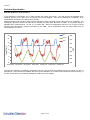
1
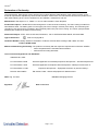
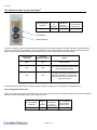
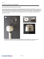
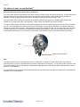
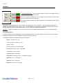
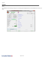
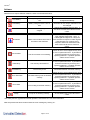
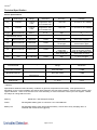
Gas Clam® Instrument User Manual V2.1 Gas Clam Instrument User Manual Part number: 25001 GasClam® Page 1 of 48 GasClam® Contents Declaration of Conformity .................................................................................................................................................... 3 Introduction to GasClam® ................................................................................................................................................... 4 ® The effects of water on your GasClam ............................................................................................................................. 5 Keeping your GasClam dry and clean in regular use ................................................................................................ 5 Effects of flooding on data and GasClam ................................................................................................................ 10 ® Optimising GasClam Performance .................................................................................................................................. 11 Getting Started .................................................................................................................................................................... 12 Packing list ............................................................................................................................................................... 12 Turning on the GasClam .......................................................................................................................................... 12 Physical Characteristics ........................................................................................................................................... 13 How the GasClam Works and access areas ........................................................................................................... 14 Software Installation ................................................................................................................................................. 15 System Requirements.............................................................................................................................................. 15 Running the installation software ............................................................................................................................. 15 Battery Change ........................................................................................................................................................ 16 Software ............................................................................................................................................................................... 17 Connecting ............................................................................................................................................................... 17 Main Screen ............................................................................................................................................................. 18 Last reading stored .................................................................................................................................................. 19 Errors ....................................................................................................................................................................... 20 Switching off the unit ................................................................................................................................................ 23 Setup ........................................................................................................................................................................ 24 Sampling Rate ............................................................................................................................................ 24 Sample count .............................................................................................................................................. 24 Device ID .................................................................................................................................................... 24 Venting ........................................................................................................................................................ 25 Water height ................................................................................................................................................ 25 Unit date and time ....................................................................................................................................... 26 Write Settings to GasClam ......................................................................................................................... 26 Erasing Data Memory ................................................................................................................................. 26 Return to main screen................................................................................................................................. 26 Downloading ............................................................................................................................................................ 27 Viewing Data ............................................................................................................................................................ 28 Selecting file for display .............................................................................................................................. 28 Data Display Options .................................................................................................................................. 28 Sampling data ............................................................................................................................................. 29 Selecting data channel................................................................................................................................ 30 Displaying multiple parameters ................................................................................................................... 31 Import data into External Spread sheet ...................................................................................................... 32 Infograph ..................................................................................................................................................... 33 Start-Stop data ............................................................................................................................................ 33 Calibration Data .......................................................................................................................................... 34 Error Messages ........................................................................................................................................... 34 Eeprom ....................................................................................................................................................... 34 Bump Test ................................................................................................................................................................ 35 Other Tests .............................................................................................................................................................. 37 Installing GasClam in a Borehole ...................................................................................................................................... 38 Service and Calibration ...................................................................................................................................................... 39 Unit calibration ......................................................................................................................................................... 39 Service ..................................................................................................................................................................... 39 User serviceable parts ............................................................................................................................................. 39 Spare parts for users ............................................................................................................................................... 41 Technical Specification ...................................................................................................................................................... 42 Sensor Specifications .............................................................................................................................................. 42 Cross sensitivities and sensor performance: ........................................................................................................... 44 Update Log .......................................................................................................................................................................... 48 Page 2 of 48 GasClam® Declaration of Conformity The manufacturer, Elok-Opava, hereby declares and confirms that the characteristics of the product conform to the technical requirements stipulated by the technical standards. Furthermore, the manufacturer declares the product to be safe whilst adhering to the correct conditions for its installation, maintenance and use. Manufacturer: Elok-Opava s r.o., Sàdek 17, 747 75 Velké Heraltice, Czech Republic Product Description: A landfill Gas monitor designed for in-situ borehole monitoring. The entire casing is made from solid stainless steel. The battery pack is in the upper part of the housing in a flame-proof casing. The measuring unit consisting of four gas sensors is located in the intrinsically safe lower part of the housing. The valves, pump and filter assembly are located at the bottom of the housing. Authorised Subject: FTZÚ, AO 210, NB 1026, Pikartská 7, 716 07 OSTRAVA-RADVANICE, IČO-00577880 Type of Protection: II 2G Ex d ib [ib] IIB T4 Certificate Number: Quality assurance notification: FTZÚ 02 ATEX Q 025 according to EN 13980, CE 1026 FTZÚ 07 ATEX 0105X Method of Determining Conformity: The product’s conformity with the respective requirements of directive 94/9/EC - it was compared with the submitted documentation - it was tested according standards List of Technical Regulations and Standards: 02600-00-001, NKO PTTI EN 60079-0:2006 Electrical Apparatus for Potentially Explosive Atmospheres – General Requirement PTTI EN 60079-1:2004 Electrical Apparatus for Explosive Gas Atmospheres. Flameproof enclosures ‘d’ PTTI EN 60079-11:2007 Directive 2004/108EC Explosive Atmospheres – Equipment Protection by Intrinsic Safety ‘I’ EN 61326-1:2006 – Electrical Equipment for Measurement Name: Ing. Jiri Klein Signature: Position: Managing Director Date: 03/06/2008 Page 3 of 48 GasClam® Introduction to GasClam® GasClam is the world’s first in-situ borehole gas monitor, suitable for the detection of a wide range of gasses commonly found in borehole monitoring, including Methane (CH4), Carbon Dioxide (CO2) and Oxygen (O2). In addition to this the GasClam monitors temperature, barometric pressure and borehole pressure. All of these readings can be taken at programmable intervals, providing an invaluable set of data to the user. The default setting for the GasClam is to take readings every hour, giving it an operational life of approximately one month (with rechargeable batteries). Data is downloaded either using a computer or via an optional modem and can be viewed within the GasClam software or exported for analysis in Excel. Whilst connected to the software the settings of the GasClam unit can be altered, including the frequency at which samples are taken and selecting venting options. In addition to the sensors already mentioned, the GasClam can be upgraded with a Photo ionisation Detector (PID) for detection of Volatile Organic Compounds (VOC’s), a Carbon Monoxide (CO) sensor, Hydrogen Sulphide (H2S) sensor and a water depth sensor should the data be required. It is recommends that regular customer bump tests take place in conjunction with an annual service and calibration, which is performed by the service department or an approved service centre. Before using the GasClam you must read this manual paying particular attention to the sections covering optimisation of GasClam performance and the effects of water on your GasClam. Note: Before removing the GasClam from the field it must be run once in atmosphere to purge any hazardous gasses. ® GasClam is a registered trade mark of Intelisys Limited t/a Salamander Group Page 4 of 48 GasClam® The effects of water on your GasClam® GasClam is designed to overcome – as far as possible – the requirement to: measure gas concentrations, measure borehole and atmospheric pressure, allow a venting pathway between the borehole and atmosphere. To measure gas concentrations the gas must be dry and measurements of atmospheric pressure should not include the pressure of overlying water. As the GasClam can be in a position liable to flooding from above (flooded headworks) and below (high borehole water level) your help is required to optimise the performance of your GasClam by: carrying out simple preventive and remedial maintenance being aware of the limitations of data gathered under flood conditions. Keeping your GasClam dry and clean in regular use To dry the gas before measurement by the CH4 and CO2 sensors there is a moisture stripping filter in the bottom section of the GasClam. Over time this will hydrate and its ability to remove moisture will decrease. If moisture is not successfully removed, concentration readings can be effected. The amount of samples that can be taken will depend on temperature and humidity. The table below shows how many samples can be taken at 90% Relative Humidity (RH) at different temperatures (90% RH is assumed to be worst case). Temperature °C 1 5 10 15 20 25 30 35 38 No. of Samples at 90% RH 3455 2620 1850 1320 950 700 520 390 330 Typically temperatures in a borehole will not exceed 15°C and not go below 3°C however, this will depend on installation. If the GasClam is used above ground then temperatures can vary more widely. The rechargeable battery on the GasClam lasts approximately 670 samples. To ensure the GasClam does not take more samples than the filters capacity use the table above to set the sample count (See GasClam Set up, pg. 24) to below the number of sample the filter will last at that temperature. E.g., if the borehole is 30°C set the sample number to less than 520. It is unlikely humidity in the borehole will be above 90% all the time and to help assess how to manage the filter after the first installation there is an indicator system. The indicators work differently below 30°C and above 30°C Filter management below 30°C Below 30°C the top indicator turns pink after approximately 40% of filter life and the bottom turns pink after 50% of filter life. For 15°C and 90% RH, the indicators will change in accordance to the table below. Page 5 of 48 GasClam® The effects of water on your GasClam® Environmental conditions Max No. of samples 15°C / 90% RH 1320 No. of samples to turn top indicator pink 490 No. of samples to turn bottom indicator pink 730 Top indicator Bottom indicator To asses if the filter needs to be changed when the batteries are replaced inspect the filter indicators. If both indicators are blue, the filter can be used again. If the top indicator is pink and the bottom indicator is blue the filter can be used again. If both indicators are pink the filter must be changed. This is summarised in the table below: Colour of top indicator Colour of bottom indicator Action Blue Blue Don’t change Pink Blue Don’t change (but will probably need to be changed next time) Pink Pink Change and check instrument for signs of moisture in the instrument. Contact local service centre if any signs of moisture If both indicators turn pink after 1 battery life (670 samples) contact your local supplier for sampling advice. Filter management above 30°C Above 30°C and high humidity the indicators do not represent 40% and 50% of the filters lifetime, below is an example of when the indicator’s change colour at 38°C and 98 % RH: Environmental conditions Max No. of samples 38°C / 98% RH 300 No. of samples to turn top indicator pink 240 Page 6 of 48 No. of samples to turn bottom indicator pink 360 GasClam® The effects of water on your GasClam® When sampling above 30 °C follow the table below: Colour of top indicator Colour of bottom indicator Action Blue Blue Don’t change Pink Blue Change Pink Change and check instrument for signs of moisture in the instrument. Contact local service centre if any signs of moisture. If sampling in the same borehole again reduce the number of samples the gasclam will take so both indicators do not turn pink Pink Page 7 of 48 GasClam® The effects of water on your GasClam® How the GasClam prevents water entering from above To prevent water reaching the vent pathway the snorkel should always be attached to the vent hose barb. The top of this should be supported so it is located at the top of the headworks to reduce the chance of water ingress. In situations where the headworks is likely to be flooded the hose barb must be replaced by the vent blank. The supplied box spanner can be used to remove the hose barb and the supplied vent Alan key used to replace with the vent blank and washer. If the vent blank is inserted you should set it in the setup window (see pg. 24). The Atmospheric pressure will not be measured in this mode. A B The GasClam should always have the snorkel attached to the vent hose barb (A). In situations where the headworks is likely to flood the hose barb must be replaced by the vent blank and washer (B). Page 8 of 48 GasClam® The effects of water on your GasClam® How the GasClam prevents water entering from below To prevent water entering the GasClam from below a water proximity sensor sits lower than the inlet. If water rises up the borehole and touches the water proximity sensor the GasClam will not sample. When water goes back down the borehole the water proximity detects this and the sampling programme will continue after 1 hour. To prevent water from reaching the inlet barb and therefore prevent water ingress, the moisture filter section cover creates an air pocket at the base of the GasClam. Water cannot rise while the air pocket is present. To improve water ingress from below, the moisture stripping filter cover and water proximity sensor have been increased by 5 cm. This stops water from reaching the inlet barb for at least 7 days when the GasClam is completely submerged with 20 cm of water above its head. If the GasClam is immersed for longer than this, the user must check the instrument to ensure water has not reached the inlet barb before restarting the GasClam. If the end user thinks water may have reached the inlet barb they must contact their local service centre as water may be inside the GasClam pneumatics. Inlet Water Proximity Sensor N.B The water proximity senor on the GasClam works by conductivity. As water is a polar solvent when it touches the proximity sensor a circuit is completed which prevents the GasClam from sampling. If a non-polar phase is present, such as oil, that is floating on top of the water in a borehole the water proximity sensor will not detect it and therefore it can be sucked in to the GasClam. If a non-polar phase is present above the water and there is any chance that it may rise to the base of the instrument the GasClam must not be installed. Page 9 of 48 GasClam® The effects of water on your GasClam® Effects of flooding on data and GasClam When the unit is not sampling it has an ingress protection rating of IP-68 However, Immersion will effect data and May require subsequent corrective action These effects and requirements will differ whether immersed from above, i.e. flooded headworks, or from below, i.e. rise in borehole water level, see table below: Flooded Headworks Effects on data Effects on GasClam Should vent breather be submerged: atmospheric pressure reading will be incorrect and will remain incorrect Scheduled venting will be ineffective. If submerged for an extended period the vent pipe may become flooded. The vent breather may become clogged by dirty water. Flooded Borehole Effects on data Effects on GasClam Remedial action Preventive maintenance Use borehole pressure as approximate replacement or use data from another source If chamber is known to flood, or is already full of water Choose another chamber Or replace snorkel with bolt When GasClam is visited Check data and call service centre if atmospheric pressure looks strange and they will advise If chamber is liable to flooding replace vent breather each visit Remedial action Should water reach the bottom of the GasClam the inflow and outflow valves will remain closed and no samples will be taken: borehole pressure reading will be incorrect gas concentration readings will be incorrect None Data points collected whilst the sampling cycle was disabled will be marked None Page 10 of 48 Preventive maintenance If borehole water level is known to be high or is already full of water Chose another chamber Or extend the borehole above ground level In some circumstances if the GasClam is removed from a borehole where water has been above the base of the GasClam a droplet of water may fall on the inlet. Every time a GasClam is removed from a borehole the inlet should be checked to see if a water droplet is on it. If so dry with a cloth. If there is any chance water may have entered the inlet contact your local service centre and do not start GasClam GasClam® Optimising GasClam® Performance Read the ‘Cross sensitivities and sensor performance’ section to understand how each gas is detected and the implication of environmental conditions on their detection. Understand the implication on sampling and bump testing if a 5% CO2 sensor is installed (see section technical specification, pg 45) To optimise GasClam performance, follow the advice in the ‘effect of water on your GasClam section’ At least every month the GasClam should be removed from the borehole (if installed for long periods). When removed the GasClam should be: Downloaded and the data checked – if there are any problems contact your local service centre. The GasClam should be inspected for any signs of wear and tear – especially water ingress The moisture stripping filter changed (see pg 39). Check integrity of the two O-rings in the moisture stripping filter compartment, if compromised replace immediately (spares provided an accessory kit) All the channels bump tested (see pg 35) Also the GasClam should be left to run in fresh air (at least 20 samples) to allow the sensors to recover from any potential contamination, cross-sensitivities, effects of non-oxygen environments and high humidity conditions (see pg 44). Change batteries (see page 16). Check the integrity of the battery compartment O-ring, if compromised replace immediately (spares provided an accessory kit) Note: If conditions of 85% RH and 40°C have persisted for more than 10 days the H2S, CO and O2 sensors may need to be reconditioned – see pg 46. Battery life and management The rechargeable battery pack will last approximately 1 month at an hourly sampling rate and should always be used in preference to alkaline batteries. The alkaline batteries can be used when the rechargeable battery has not been charged and the GasClam must be deployed immediately. Alkaline batteries will last approximately 14 days hourly sampling. The voltage of the rechargeable pack after fully charging is 2.65 volts. Check this voltage is displayed on the battery indicator in the software front screen when a fully charged battery is installed. The battery voltage displayed is a live reading and will decrease when the GasClam actively samples as a load is being placed on it. Before leaving the GasClam observe the battery voltage during 1 measurement cycle and you will see it decrease. To ensure the battery is fully charged and has good capacity download the GasClam after 1 sample and check the voltage in the downloaded file. This should be approximately 2.5 volts or above if the battery is fully charged and has good capacity. If it is below 2.5 volts the battery life will be compromised and should not be used. If alkaline batteries are used, new cells will display a reading of above 3.0 volts on the battery indicator and the voltage recorded on the GasClam after 1 reading will be over 2.9 volts. If either voltage is below these the battery life will be compromised and should not be used. (For more information see technical specifications, pg 42,43). Note of caution if used below 0°C If the GasClam is used below 0°C in high humidity the internal valves may freeze. This will prevent the GasClam from sampling properly and a pump error will be flagged. This will not damage the GasClam; when temperature rises above 0°C it will function correctly. Typically, the GasClam is installed in boreholes below the ground and will not go below 0°C due to ground heat. If the GasClam is installed above the ground, insulation or a heater will be needed to prevent freezing. (See technical specifications for more information, pg 47) Page 11 of 48 GasClam® Getting Started Packing list Please take a little time to examine the contents of the GasClam package. Item Description Barbs (Fitted) Box spanner for removing barbs Blank (NOT Fitted) + washer Length of pipe (30cm) Battery Allen Key Vent blank Allen Key Communication cable Start cable Manual and software (on CD) Rubber Collar GasClam Unit 1.5v Duracell Batteries (Fitted) Moisture Stripping Filter Rechargeable battery Recharger Qty 3 1 1 3 1 1 1 1 1 1 1 2 1 2 1 Accessory Kit 1 Moisture stripping filter Snorkel (complete) Snorkel filter Pack of o-rings A-25066 Pack of o-rings A-25067 3 1 2 5 5 Turning on the GasClam The GasClam can be switched on and off using the remote. The remote connects to the communication port on top of the GasClam. To start the GasClam hold the button down for two seconds, the red LED will flash rapidly indicating the GasClam has started and is currently going through the processes in a sampling cycle, this equates to ‘sampling’ mode. After the sampling processes have finished the red LED flashes intermittently, this equates to the ‘measuring’ mode. To stop the GasClam press the button for two seconds, when it has stopped the LED will stop flashing, this equates to ‘sleeping’ mode No flashing Sleeping Rapid flash Sampling Intermittent flash Measuring Page 12 of 48 GasClam® Getting Started Physical Characteristics 1 5 8 4 7 3 1. 2. 3. 4. 5. 6. 7. 8. 9. 10. Communication port Pressure transducer port Pressure transducer port cap Gas inlet Gas Outlet Water proximity sensor Pressure transducer hook Battery compartment lid Vent (with hose barb) Rubber Collar 9 10 6 2 GasClam identification plates with intrinsic safety specifications. Page 13 of 48 GasClam® Getting Started How the GasClam Works and access areas Page 14 of 48 GasClam® Getting Started Software Installation System Requirements The GasClam software needs 30MB free space on the hard disk for installation. The programme will run on the following platforms: - Windows 98 - Windows 98 Second Edition - Windows 2000 service pack 3 - Windows ME - Windows Server 2003 - Windows XP service pack 2 - Windows Vista - Windows 7 The programme needs .Net Framework 2.0 (x86) installed to run properly. This version is included on the software CD, alternatively it can be downloaded from the Microsoft website. Running the installation software Insert the installation CD or USB stick and copy the software folder on to the PC. There are two installation options. 1) If you have an old version of DotNetFX, 2.0 (x86) then double click the ‘setup’ icon to update the DotNetFX. (If you already have this version and you try to upgrade an error will occur, ignore this and go to the next option) 2) If you already have this version of DotNetFX then double left click the ‘GasClamUnit’ icon. The guide will then take you through the installation process step by step. The default location for the GasClam software is: C:\Program Files\Salamander\GasClam Page 15 of 48 GasClam® Getting Started Battery Change Warning: For reasons of intrinsic safety, batteries MUST NOT be changed within potentially flammable areas. Always ensure you are in a safe area before carrying out any type of maintenance on your GasClam Battery types that can be used: For Intrinsic Safety and reduced risk of explosion you must only use (2 x 1,2V) LR20 Nickel-metal hydride Saft VH D 9500 rechargeable pack (provided) or 2 x Duracell 1.5 V LR20 Alkaline-Manganese MN1300 batteries. Do not mix old and new batteries within the same unit, change both batteries at the same time. Failure to do so will reduce battery life of the new cell fitted. The battery compartment is accessed by removing the 4 screws from the battery compartment lid, see diagram. To remove the batteries tilt the GasClam until they fall out. Replace with the stipulated batteries positive terminal facing down. Take care when replacing the cover to ensure the O-ring is not damaged by following the instructions below: The integrity of this O-ring should be checked every time the batteries are replaced. This needs to be replaced if any damage is noticed. Push the battery compartment lid down square on the GasClam. When the O-ring is resting on the battery compartment push the lid down evenly on both sides to ensure it travels down square. This will prevent damage to the O-ring. When the O-ring is sitting in the compartment loosely tighten the screws. The lid must sit flush with the head of the GasClam otherwise the intrinsic safety of the unit will be compromised. When tightening the cover alternate between screws to ensure the cover sits on the GasClam squarely. If this is not done the Oring may be damaged. Page 16 of 48 GasClam® Software Connecting The GasClam is connected to a computer using the supplied cable via the communication port on top of the GasClam and a serial port. If the computer does not have a serial port use a standard USB/Serial converter. You can either connect the unit before or after starting the software. If the software is opened before the GasClam is attached the screen appears as below. In this mode the options available are to view data (see later) or to close the application. After the GasClam is connected the screen will update (similar to below) with the device ID displayed. GasClam ID The window is divided in to 3 sections, navigation tabs (view data, download, setup and user calibration, bump test, other tests), Online Status and Last Reading Stored. Page 17 of 48 GasClam® Software Main Screen Battery status – displays battery voltage alongside a power bar, the bar changes colour according to capacity providing a rough guide to battery life*. Green: Capacity is fine for a long sampling period Orange: Batteries need to be replaced very soon Red: Replace batteries immediately *The voltage in the battery will decrease when the GasClam is sampling due to a load on the batteries, this is the voltage that should be used to assess battery condition (This is also the voltage that is logged). Note. If the battery capacity is no longer sufficient for the running of the unit during a programme the unit automatically interrupts the cycle and switches to sleeping mode, this will be logged as a battery error. The data is stored in the flash memory therefore the data will remain in the GasClam even if the batteries are completely flat. Samples Remaining – displays the remaining number of samples that can be stored in the memory. Samples Taken – When the GasClam is in sleeping mode this reads ‘samples taken’ indicating how many sampling points are stored on the memory. When the GasClam is in sampling mode it reads ‘sample count’ and displays the number of finished cycles and the total number of cycles in the programme. For example, 254/4500 means that 254 cycles from 4500 required cycles have finished. Sampling every - shows the period between sampling. For example, value “60 mins.” means that sampling frequency is 1 hour. End Date – displays the date and time that the sampling programme will finish. Serial Number – displays the serial number of the unit. COM port – displays which port the unit is connected to. Status – displays the mode of the unit: When the unit is running a programme the following modes are possible: Sampling – the GasClam is actively making a measurement. Measuring – the GasClam is between sampling periods. When the GasClam is not running a programme the following modes are possible: Sleeping – the unit is not running a programme. In this mode data can be downloaded and the unit programmed. Clear flash – the unit is erasing flash memory data. If the GasClam is not functioning correctly the status will read ‘undefined status,’ if this occurs contact customer services immediately. Page 18 of 48 GasClam® Software “START/STOP” Button – this has several modes: The unit is in sleeping mode, to start the GasClam left click the button. The unit is actively sampling (it can be stopped by left clicking the button), after this has finished the button changes to: The unit is between samples and the programme can be stopped by left clicking the button. After starting the GasClam through the software wait until the first cycle is complete. The last readings stored will be updated and these values can be used to check that the GasClam is functioning correctly. Also this will remind the user that the GasClam has been started before leaving it for a period of unmanned data collection. Firmware – shows the firmware version in the unit. Always use the software designated for the given firmware version. Last reading stored The last recorded values are displayed in the ‘Last Reading Stored’ box. If the sampling cycle has started, these values will display ‘measuring’ and are updated throughout the sampling process. The displayed ranges of individual sensors are as follows: Methane: 0-100% or 0 – 5 % Carbon Dioxide: 0-100% or 0 – 5% Oxygen: 0-25% Borehole Pressure: 800 -1200 mBar Barometric Pressure: 800 – 1200 mBar Temperature: -5°C to +50°C Optional Water Level: 0-25m Optional Dual CO/H2S sensor: 0-500ppm/0-200 ppm Optional VOC: 0 -4,000 ppm Optional H2S 0 -5,000 ppm Optional CO sensor 0 -100 ppm Page 19 of 48 GasClam® Software Errors If the GasClam is not functioning correctly an error message will be displayed at the top of the Software home screen, see below. Page 20 of 48 GasClam® Software Different errors require different solutions, these are summarised below; Error Reason Solution Low Battery Battery voltage is below 1.8V for 10s GasClam will run but batteries need to be changed immediately Flat Battery Battery voltage is below 1.8V for 60s GasClam will not sample, batteries must be changed Filter Error* The moisture stripping filter is clogged Change the moisture stripping filter. If this does not work then call the service centre. Water in the borehole has risen to the base of the GasClam When water level drops the GasClam will start sampling again after 1 hour. If submerged for longer than 7 days the user will have to inspect for water ingress. If OK sampling can continue if any suspicion water has reached the inlet barb contact local service centre for advice. The AD convertor is not working. Check to see if it has happened only once or if it is a permanent error. If permanent, reset the GasClam by removing and replacing batteries. If problem persists call the service centre. The memory has timed out Check to see if it has happened only once or if it is a permanent error. If permanent, reset the GasClam by removing and replacing batteries. If problem persists call the service centre. The memory is full Download GasClam and clear memory The flash memory has not worked correctly Check to see if it has happened only once or if it is a permanent error. If permanent, reset the GasClam by removing and replacing batteries. If problem persists call the service centre. Error writing to the flash memory Check to see if it has happened only once or if it is a permanent error. If permanent, reset the GasClam by removing and replacing batteries. If problem persists call the service centre. Pump is not working correctly Check battery level, if OK call service centre. Immersion AD Overflow Flash Busy Full Memory Error SPI Flash Error Write Pump* *See ‘filter pressure’ pg 29 and ‘Potential problem if used below 0°C’ for more information. After the problem has been resolved clear the error message by clicking ‘clr’. Page 21 of 48 GasClam® Software To help trouble shoot errors the service centre will need the .gcl, .gce and .csv file (see page 23) The VOC, CH4 sensor and the CO2 sensor have an in built test which is run before every sample. In the unlikely event the test fails low voltage is written below the sensor in the ‘last readings stored’ section of the front screen, see below. If this happens contact your local service centre immediately. A log of the errors is kept and can be viewed in the ‘Error Messages’ section in the view data section of the GasClam software, see below: Error symbol Error message tab Page 22 of 48 GasClam® Software Switching off the unit If the unit is not going to be used for a long period it is recommended that it is turned off using the ‘OFF’ button, this reduces the discharge from the batteries. When the off button is clicked a message will appear to ask if you really want to switch off. If the Yes button is clicked the following appears: The GasClam will turn off after the communication cable is disconnected, until then the main screen will appear as below: The GasClam will turn back on when the data cable is attached again. Page 23 of 48 GasClam® Software Setup The GasClam is programmed in the setup window and is accessed by left clicking the ‘set up’ navigation tab, and the set up window then appears as below. Sampling Rate The sampling rate is defined in the Set Sample Rate box, the fastest sampling rate is 3 minutes (This is how long all the processes take), the longest 999 hours and 60 minutes.. Sample count The number of samples to be taken can either be set to the maximum possible by clicking the ‘Always Maximum’ button or defined by the user in the Sample count box. The maximum figure displayed is 65000 (total memory space) minus the number of stored samples, the user defined value can be up to and including this. The estimated date and time of the end the programme is displayed under the text button. This information is calculated as follows: (Sample count * sample rate) + actual date and time. This is set to 800 as default to ensure the moisture stripping filter is not compromised. Device ID The user can specify the name of the GasClam in the Device ID box. This is useful if there is multiple GasClam on a site as the borehole number can be allocated to the GasClam. This information is used to create a filename when the data is downloaded. Page 24 of 48 GasClam® Software Venting The GasClam has four venting modes, which can be selected in the Venting box (see below): Always Closed – Always Open – The vent is always closed The vent is always open Open once per day - The vent opens once a day for a period of time defined by the user. The vent opens immediately after the first sample and shuts after the allocated time. Open after every – The vent opens and stays open for user defined periods. If the GasClam is to be located in a wet area and the vent blank is installed tick the vent plug inserted box. Water height The GasClam can measure the water level in the borehole using an optional pressure transducer. To enable the water level pressure transducer the ‘water level enabled’ box in the Distance water height area needs to be ticked. The GasClam reports the level in meters below ground level (mbgl) however, in order to calculate this distance 3 parameters need to be entered; water density, water sensor length and the distance of the GasClam to the surface, see diagram below. Pure water has a density of 1000 kg/m3 at 4°C. Borehole pressure affects the water level reading but this is automatically corrected. Page 25 of 48 GasClam® Software Unit date and time The time and date of the unit and computer are displayed in the Date and Time box, and are synchronised by left clicking the Set Time tab. The date and time is not stored when the unit is switched off or when the batteries run or are changed. Note. The time on the unit is likely to differ from the computers if the device was programmed on a different computer to the one it now is connected to. Write Settings to GasClam To activate a change in the setup up menu the ‘write settings to GasClam’ button must be clicked. If this is successful a message saying ‘Settings written successfully’ will appear. Click OK to continue. Erasing Data Memory To erase all the data from the flash memory left click the Erase memory button. The status will change to ‘Clear Flash’ during this process, when this is finished the status will change to ‘Sleeping’ Warning – This process erases stored data permanently. Make sure you have downloaded the data from the GasClam onto your computer. Return to main screen To return to the GasClam software’s main window use the back button. Page 26 of 48 GasClam® Software Downloading To download the GasClam left click the ‘Download’ button. This opens a standard Window’s ‘save as’ window. The default file name is the device ID followed by the time and date. Remember to have ‘view negative values’ selected, see page 14. After choosing the file name and location the download begins when save is clicked, the length of the download will depend upon the amount of data. Three files are produced .gcl .csv .gce This is the file format to read within the GasClam software. This file contains all the recorded parameters and can be used to view and plot the data in excel This file contains information on the settings and performance of the GasClam. This is used by service centres for trouble shooting. Page 27 of 48 GasClam® Software Viewing Data The data viewer is accessed via the ‘View Data’ navigation button on the main screen. Selecting file for display To open a file click either the ‘…’ or the open button, this allows you to browse through your computers folders. Data Display Options There are 5 types of data that can be viewed, Sampling Data, Start-Stop Data, Calibration Data, Error Messages and Eeprom. These are accessed using the tabs. Page 28 of 48 GasClam® Software Sampling data To display the sampled data click the ‘Sampling-data’ button. The following parameters are displayed, see example below. Date: in the format dd/mm/yyyy hh:mm CH4 %: Methane, % v/v CO2 %: Carbon dioxide, % v/v CO: Carbon Monoxide, ppm O2 %: Oxygen, % v/v VOC: Volatile Organic Compound, ppm H2S: Hydrogen Sulphide, ppm BH: Borehole pressure, mBar Atm: Atmospheric pressure, mBar Diff: Differential pressure between borehole and atmosphere. If the value is negative it means the pressure in the borehole is lower than atmospheric and if the pressure is positive it is higher than atmospheric. °C: Temperature in degrees Celsius mbgl: Water level meters below ground level Battery: Battery capacity, volts. The voltage recorded is the voltage under maximum load. (The voltage bar on the front screen is a live reading of the battery voltage and will change during the sampling sequence as the load on the battery changes) Filter Pressure: Every time a sample is taken the borehole pressure is measured, then when the pump is running the pressure whilst the pump is running is compared to the borehole pressure. The maximum differential is recorded under as the ‘filter pressure’. If this exceeds 50 mBar a filter error occurs. The most likely cause of the problem is the filters performance has reduced causing the flow path in the GasClam to be constricted. If this happens replace the filter. If the problem persists something else is causing the blockage and the service centre must be contacted immediately. If the pressure is below 5 a pump error is flagged. This will be due to a faulty pump or faulty power supply to the pump. The filter pressure is normally between 15 – 25. It is possible to order the displayed data according to individual parameter by clicking the column header, one click arranges them in ascending another click arranges them in descending order. Example of Sampling Data Screen Page 29 of 48 GasClam® Software To view the data in graphical form click the Graph/Data view toggle button. Graph/Data view toggle button This opens the Graph view window, shown on next page. Selecting data channel To select a data channel click the desired parameter from the ‘Data Channel’ box, see below. Multiple parameters can be displayed by clicking more parameters. Page 30 of 48 GasClam® Software Displaying multiple parameters Page 31 of 48 GasClam® Software Import data into External Spread sheet Data is provided as a CSV file and can be imported into various spreadsheets for manipulation. This is normally done using the import function and selecting delimited and then selecting comma as the separator. Page 32 of 48 GasClam® Software Infograph All the values of the parameters at any particular time can be displayed by using the info graph window. This is turned on by clicking the ‘view value’ box. These values will update as the cursor is dragged over the graph. Start-Stop data To display the sampling log of the unit click the ‘Start-Stop’ Data button. Information regarding when and how the unit was started and stopped, date the action was taken, memory space left and sampling frequency and how many samples was taken is reported, see below for an example. Page 33 of 48 GasClam® Software Note. If the GasClam has stopped due to low battery a note indicating this will be left in the code column. Calibration Data In this section the calibration date and constants are displayed. Error Messages All errors are logged and can be viewed here (see pg 20 for details) Eeprom Firmware constants are displayed in this tab. These are useful for the service centre when trouble shooting. Page 34 of 48 GasClam® Software Bump Test You can check the performance of the sensors by running a bump test on your GasClam. During a bump test a known concentration of gas is pumped through the GasClam and the value measured is displayed. If the measured concentration is within the tolerance of the sensor the bump test is passed and indicated by a tick, if it is outside this range the bump test is failed and indicated by a cross. The values are informative only (i.e., nothing is saved on the GasClam settings) and used to decide if a calibration is required. The bump test menu is entered by clicking the ‘Bump Test’ button on the main screen. To check the performance of the relevant sensor(s) tick the box next to the sensor name, then enter the concentration of the test gas in the ‘Enter Values’ column. If you want to test atmospheric gas the ‘Enter values for Air’ button can be used to set the concentrations. Before starting the test connect the gas line to the inlet barb. The test is then started by clicking the ‘Start’ button. The whole bump test cycle will take approximately two minutes after which the measured concentration is displayed in the ‘Values’ column and the result of the test is indicated by a cross or tick. If a cross occurs, contact your service centre and they will advise on action. The sensors must be checked at atmospheric pressure, as the calibration gas bottle will be pressurised it is important that the excess pressure is vented. This is achieved by attaching a T-piece between the gas bottle and inlet, see diagram below. Alternatively and on demand regulator can be used. Tick box Enter concentration of Gas here Measured value Result N.B. The flow rate of the GasClam is 420 ml/minute therefore a flow regulator with a minimum flow of 500 ml/min is required. Excess Pressure GasClam Inlet Gas Page 35 of 48 GasClam® Software The recommended gas bottles to use for bump tests are: Bump test Cylinder 1 Gas Concentration CO 40ppm (balance air) 20ppm (balance air) 100ppm (balance air) 60/40/0% 2.5/2/20.9% Pure (zero O2) 2 H2S 3 Isobutylene 4 5 6 CH4/CO2/O2 CH4/CO2/O2 N2 Note: It is possible to bump test multiple sensors simultaneously; however, some of the sensors will have cross sensitivities at the bump test concentrations therefore, the sensors are separated out. H2S levels at the concentrations the GasClam is bump tested at affects the performance of the CO sensor therefore; the CO channel is bump tested before the H2S channel. Also CH4 at 60% will inhibit the PID sensor so it is bump tested separately. (See cross sensitivities section for more information) Also if a 5% CO2 sensor is fitted it will take 2/3 samples for the GasClam to read the bump test gas concentration. This is because the filter causes a lag when CO2 concentration increase or decrease (See sensor performances section) The order to bump test the sensors in is shown below (If the sensor is not installed ignore that step): Due to the different available combinations of CO2/CH4 sensors there are 3 different scenarios for bump testing the sensors. 1) 100% CO2 and CH4 Sensors st nd Bump test step Gas 1 Concentration 1 CO 0 40 ppm 2 H2S 0 CH4 CO2 O2 Isobutylene (Air) 0 0 20.9% 0 20 ppm (60/40 CH4/CO2) 60% 40% 0% 100ppm (Bottle) 3 4 Calibration table 1 Page 36 of 48 2 Concentration GasClam® Software 2) 5% CH4 and CO2 sensor (if other sensors are fitted follow the relevant steps in the table 1) Use N2 for 0 Bump test step st Gas 1 Concentration (Gas bottle) (N2) CH4 CO2 O2 1 nd 2 Concentration (2.5/2/20.9% CH4/CO2/O2) 0 2.5 2* 20.9 0 0 * 2/3 samples will be needed to reach concentration Calibration table 2 3) Mix of any 5% and 100% CO2/CH4 sensors (if other sensors are fitted follow the table 1) Bump test 5 % CO2 sensor first if installed Use N2 for 0 Bump test step Gas 1 Concentration 1 CO2 N2 for 5% sensor, Air for 100% sensor 2* or 40% 2 CH4 N2 for 5% sensor, Air for 100% sensor 2.5 or 60% 3 O2 0 (N2) 20.9 (Air) st * 2/3 samples will be needed to reach concentration Calibration table 3 Other Tests This section is for service centres. Page 37 of 48 nd 2 Concentration GasClam® Installing GasClam in a Borehole The GasClam is designed to fit in to a 50 mm borehole. The recommended headworks are 8” Monitoring wells from Stuart Wells (http://wellservices.stuartgroup.ltd.uk/) and should be installed following the diagram below: It is important to have the stand pipe a maximum of 3 cm above the base of the headworks, this will ensure the GasClam will fit under the lid of the cover. The headworks must be concentric to the standpipe for the GasClam to be housed correctly. The standpipe must also be cut square to allow a good seal. If a protective cover is to be used make sure this ends below the top of the standpipe otherwise the GasClam will not fit correctly. Page 38 of 48 GasClam® Service and Calibration Unit calibration Calibration should only be carried out by an authorised GasClam distributor. Service The GasClam should be regularly serviced to ensure correct and accurate operation. It is recommended that it should be serviced and recalibrated every 12 months. The GasClam is ATEX certified for use in potentially explosive areas therefore it should only be serviced by qualified engineers. Failure to do so will invalidate the warranty. User serviceable parts Changing Moisture stripping filter: Follow the advice in ‘The effects of water on your GasClam’ section pg 5, 6 for filter management . To change the moisture filter follow the instructions below. The instrument should never be operated without the filter. To remove filter; 1) Put thumbs beneath the filter and push up with both To replace filter; 1) Connect the tygon tube to the barb 2) Push the fitting together 3) Push filter completely down firmly from the top. Page 39 of 48 GasClam® Service and Calibration Snorkel: The snorkel should be checked regularly, if there is any damage replace immediately Collar: Inspect the collar regularly, if there is any signs of damage replace immediately. Battery compartment O – ring: Inspect regularly and if there is any sign of damage replace immediately Item Ref. Part Number Description 1 25039 Water Level Sensor 2 TBC TBC 3 25030 RS 232 Communication Cable 4 25031 Push Button Control 5 25109 Moisture stripping filter cover 6 25033 Rubber Collar 8(10) 25035 (2/SA5-8) Vent hose barb (vent blank) 7 A-25114 Moisture Stripping Filter (pack of 3) 9 25036 Water level comms port cover and cable 11 25037 Communication Cover and Cable 12 1/BA-03 Battery Alkaline MN 1300 D (2 required) 13 25065 Rechargeable Battery Pack A-25110 Battery Compartment bolt and washer (retained) Pack of 4 25062 Charger NiMH ECH 1.1 14 25038 Battery Cover (complete) 21 A-25066 O-Ring for filter section (Bottom) and battery compartment Pack of 5 22 A -25067 O-Ring for filter section (upper) pack of 5 A-25064 Snorkel A - 25083 Accessory Kit Page 40 of 48 GasClam® Service and Calibration Spare parts for users Page 41 of 48 GasClam® Technical Specification Sensor Specifications Sensor Method/type Range Resolution CH4 Infrared 0-100 % 0-5% CO2 Infrared 0-100 % 0-5% Oxygen Electrochemical 0-25 % 0.1 % 1% of measuring range above 50%, 0.5% below 50%. 1% of measuring range above 50%, 0.5% below 50%. Accuracy Linearity ± 2% FSD +/- 2% FSD or 10% reading ± 2% FSD +/- 2% FSD or 10% reading ± 5% of reading ± 1 digit >1 % O2 deviations @ 10% O2 <± 3ppm at 0, ± 3% at 250 ppm <± 1 ppm at 0, ± 2% at 100 ppm Linear at 0 - 500ppm, error at full scale ± 15ppm Linear at 0 to 200ppm, error at full scale ± 4ppm <± 3ppm at 0, ± 5% at 250 ppm <± 1 ppm at 0, ± 2.5% at 50 ppm ± 5% of reading ± 1 digit Linear at 0 and 400ppm, error at full scale ±15ppm Linear at 0 and 20ppm, error at full scale <±4 ppm Dual CO/H2S sensor CO Electrochemical 0-500 PPM 1 PPM H2S Electrochemical 0-200 PPM 1 PPM Single CO or H2S sensor(s) CO Electrochemical 0-5000 PPM 1 PPM H2S Electrochemical 0 - 100 1 PPM VOC PID 0-4,000 PPM 1 PPM Environmental Barometric Pressure Borehole Pressure Temperature Water depth* Method / Type Piezoelectric Piezoelectric Internal Chip +/- 5% to 100 ppm Range Resolution 800-1200 mBar 1 mBar 800-1200 mBar 1 mBar -5°C to +50°C or 41°F to 122°F 1°C or 1°F 0 – 25 m 0.01m Piezoelectric * Optional Specifications obtained under laboratory conditions of gas flow, temperature and humidity. Field performance is dependent on the correct installation procedures being followed, environmental conditions, frequent sensor cleaning and regular calibration. Some of the sensors have cross sensitivity, for more information contact your local supplier. Details are subject to change without notice. Memory 65000 time / date stamped readings Power Rechargeable battery pack or 2 Duracell 1.5 V LR20 MN1300 Battery Life Rechargeable battery pack will last approximately 1 month at an hourly sampling rate in a GasClam with all the sensors (@15°C) Page 42 of 48 GasClam® Technical Specification If used at a slower sampling frequency note the NiMH batteries self-discharge at a rate of 15% - 20% per month. Duracell 1.5 V LR20 MN1300 Alkaline-Manganese batteries will last approximately 14 days hourly sampling in GasClam with all the sensors. The self-discharge of alkaline batteries is much less and as a rule of thumb the alkaline batteries will last approximately 300 samples over a time scale of up to 1 year. The discharge curves of the rechargeable battery pack and alkaline batteries are below: Rechargeable battery 3 2.5 Voltage 2 1.5 1 0.5 0 0 200 400 Sample No. 600 800 Alkaline Battery 3.5 3 Voltage 2.5 2 1.5 1 0.5 0 0 50 100 150 200 Sample No. Page 43 of 48 250 300 350 GasClam® Technical Specification Case High Quality Stainless Steel Weight 6 kg or 13.2 lb Protection IP – 68 (continuous submersion, 20 cm above head of GasClam for 7 days) Operation –10 to +40 °C or 41°F to 122°F Approvals CE, EMC ATEX (-20 to +50°C alkaline batteries, -10 to + 40°C rechargeable battery pack) Certification rating II 2G Ex d ib [ib] IIb T4 Certificate number FTZU 07 ATEX 0105 X IECEx (-20 to +50°C alkaline batteries, -10 to + 40°C rechargeable battery pack) Certification rating Ex d ib [ib] IIB T4 Gb Certificate Number IECEx FTZU 09.0026 CSA C US (-20 to +50°C alkaline batteries, -10 to + 40°C rechargeable battery pack) Certification rating Class 1, Zone 1, Ex d ib IIB, T4 Class I, Zone I, AEx d ib IIB, T4 Certificate Number 2320892 European Patent granted, World Wide granted Cross sensitivities and sensor performance: Dual CO/H2S Sensor The CO and H2S sensors are electrochemical sensors and suffer from cross sensitivity to other gasses that may be found in the subsurface. The carbon monoxide sensor suffers especially from the cross sensitivity with H 2S, H2 and NO. The cross sensitivities with these gasses are: 15 ppm H2S will read <6 ppm on the CO channel 35 ppm NO will read <0.1 ppm on the CO channel 100 ppm H2 will read approx. 20 ppm on the CO channel The hydrogen sulphide sensor is especially cross sensitive to the following: 5 ppm NO2 will read approx. -1 ppm on the H2S Channel 35 ppm NO will read <1 ppm on the H2S Channel 5 ppm SO2 will read <1 ppm on the H2S channel 300 ppm CO will read <6 ppm on the H2S channel If the sensors have been exposed to gasses they are cross sensitive to for long periods it may take some time for the sensors to recover. The sensors can be checked after exposure to these gasses by setting the GasClam to sample every 5 minutes in clean air and the concentrations should return to zero and stabilise. If you suspect a cross sensitivity problem please contact your supplier for further advice. Page 44 of 48 GasClam® Technical Specification Single CO sensor The Single CO sensor has a filter on to reduce the cross sensitivity with H2S, NO2, NO and SO2 Filter Capacity ppm – hours 250,000 600,000 20,000 300,000 Gas H2S NO2 NO SO2 50 ppm NO will read <5 ppm 400 ppm H2 @20°C will read <60 ppm 400 ppm C2H2 will read <25 Single H2S sensor 5 ppm NO2 will read approx. -1 ppm on the H2S Channel 50 ppm NO will read <5 ppm on the H2S Channel 20 ppm SO2 will read <4 ppm on the H2S channel 400 ppm CO will read <4 ppm on the H2S channel 10 ppm Cl2 will read <-25 ppm on the H2S channel Methane Methane is measured using an infrared detector tuned in to C-H bonds. The sensor is calibrated using certified methane calibration gas and will give accurate readings providing no other C-H compounds are present. If additional hydrocarbons are present they will contribute to the reading. Carbon Dioxide Carbon Dioxide is measured using an infrared sensor tuned in to C=O. There are no other gasses commonly found in the subsurface that adsorb infrared radiation at this wavelength, so the reading will not typically suffer from cross sensitivity. 5% Carbon Dioxide Sensor When sampling concentrations up to 5% the sensor will read 90% of the real value after one sample (typically this will be within error of the sensor). For example, if you are sampling every hour and the real concentration changes from 0% – 2.5% in 1 hour (which is unlikely) the senor will read approximately 2.25%. In reality if low concentrations are present they will change much more gradually than this i.e. Sample 1 2 3 Real Conc. % CO2 0 0.1 0.3 4 0.8 Measured concentration 0 .09 (within error) 0.279 (.3-.09 = .21, .21*90% = 0.189, 0.189 + last reading (.09) = .279 (within error) 0.75 (within error) Page 45 of 48 GasClam® Technical Specification When concentration decreases the reading will also be 90% of the real value after 1 sample. Below are examples when 4.7% CO2 has been sampled and how the sensor/filter clears down in air. Sample 1 2 3 1 4.701 0.326 0.071 2 4.738 0.29 0.037 3 4.671 0.468 0.042 Oxygen The oxygen sensor is a Galvanic sensor and is very specific. It has a little cross sensitivity with CO 2, 5 % CO2 only causes a 0.1% change in reading. Humidity has a little affect on output, between 0 % to 95% rh the % O 2 change is <0.7 %. The sensor can work between 5 – 95 % RH continuously and 0 – 99% short term. VOC The VOC sensor is a mini photo ionisation detector (PID) and is sensitive to any VOC’s that have an ionisation potential less than 10.6 eV. The sensitivity of the sensor depends on the VOC present. The sensor is calibrated to isobutylene and its response to other VOC’s can be calculated using that compounds response factor. A response factor is a number, which relates the PID response to a particular VOC, to the PID response from the calibration gas (normally isobutylene). If the response of a PID to a particular VOC is eight times smaller than it is for the same concentration of isobutylene, then the response factor would be 8. Similarly, if the response factor for a particular VOC is 0.5, the response is twice that for isobutylene at the same concentration. Concentrations greater than 4% CH4 and CO2 will attenuate the response of the PID sensor. Some VOC’s after ionisation may stick to the PID lamp reducing the amount of ultraviolet light available for future measurements. Before each PID measurement is made the lamp is turned on for 30s to burn the residual VOC’s off. However, some VOC’s may be more persistent and not completely removed, if this happens the PID response will decrease. To recondition the lamp set the GasClam to sample every 3 minutes and run for 1 hour in clean air, then perform a bump test. If the sensor has not completely recovered try reconditioning for longer. If this does not work contact your local service centre. Additional CO/H2S sensor performance information If the GasClam is located in a zero oxygen environment for longer than 24 hours the CO and H 2S sensor performance may be hindered. To return the channels to optimal performance the sensor needs to be left exposed to an oxygenated environment for the same length of time as it was deprived of oxygen for. Above 85% RH and 40°C a maximum continuous exposure of 10 days is recommended. Where such exposure occurs the sensor will recover normal electrolyte volumes when allowed to rest at lower % RH and temperature for several days. If very accurate CO or H2S measurements are required it is recommended that a single CO or H 2S sensor is used. Page 46 of 48 GasClam® Technical Specification Potential problem if used below 0°C If the GasClam is used below 0°C in high humidity the valves may freeze. This will prevent the GasClam from sampling properly and a filter error and pump error will be flagged. This will not damage the GasClam; when temperatures rise above 0°C it will function correctly. Another indication that the valves have frozen is that the O 2 sensor will either go off scale positively or negatively. The atmospheric pressure channel will also have a dramatic increase whilst the valve is frozen. In the picture below a GasClam was cycled between -10 and 10 °C at 98% RH. When the temperature reaches -5°C O2 goes of scale positively and atmospheric pressure increases by 20 mBar. When temperature rises the valve thaws and O 2 concentrations are correct. O2 30 880 Temp 25 875 Atm 870 15 865 10 860 mBar Temp °C/ O2 % 20 5 855 0 850 -5 -10 30/03/2012 30/03/2012 30/03/2012 30/03/2012 31/03/2012 31/03/2012 31/03/2012 845 Typically the GasClam is installed in boreholes below the ground and the GasClam will not go below 0°C due to ground heat. If the GasClam is installed above the ground insulation or a heater will be needed to prevent freezing. If you are unsure about your GasClam installation contact your local supplier. Page 47 of 48 GasClam® Update Log Manual Version GasClam V2 Amendment Filter management section added. How to prevent water from entering updated. Packing list updated Optimising GasClam performance updated Errors up dated Bump Test Updated User serviceable part updated Part numbers updated Technical Specs updated Changes updated in version 2.1 Date Updated 20/07/2012 Page 48 of 48 Instrument Firmware 7.11.248 Instrument Software 5.4.33