1
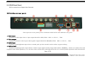
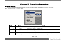
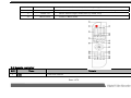
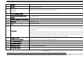
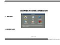
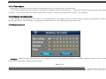
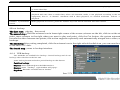
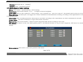
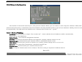
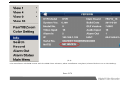
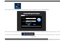
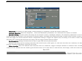
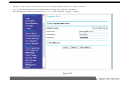
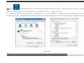
statement:
· We strive to ensure the exactness and integrality of the manual in the process of preparation, but
still errororomission is inevitable.
· The copy, transmission, plagiary, storage in retrieval system, or translation into any language
without written authorization is prohibited.
Page 1/78
Content
CHAPTER I MAJOR FUNCTION INTRODUCTION............................................................. .......................................7
CHAPTER II NSTALL INSTRUCTION……………………………………………………………………………………………………..9
2.1 INSTALL HARD DISK……………………………………………………………………………………………………………....9
2.2 INSTALL DEVICE..........................................................................................................................................9
2.3 INTERFACE ON REAR PANEL................................... ..................................................................................10
CHAPTER III OPERATION NSTRUCTION……………………………………………………………………………….…………….12
3.1 MOUSE OPERATION...................................................................................................................................12
3.2 REMOTE CONTROLLER..............................................................................................................................13
3.3 ICON INSTRUCTION...................................................................................................................................15
CHAPTER IV BASIC OPERATION...........................................................................................................................17
4
MAIN MENU................................................................................................................................................17
4.1.1 TURN ON………………………………………………………………………………………………………………………18
4.1.2 LOGIN.................................................................................................................................................18
4.1.3 TURN OFF…………………………………………………………………………………………………………………….18
4.1.4 LOGOUT.............................................................................................................................................19
4.2 TIME ADJUST AND RECORD CONFIGURATION………………………………………………..…………………………19
4.2.1 TIME ADJUST.....................................................................................................................................19
4.2.2 RECORD CONFIGURATION........ ........................................................................................................20
Page 2/78
4.3 RECORD CONTROL......................................................................... ..........................................................20
4.3.1 START TIME / MOTION DETECTION / ALARM RECORDING....................................... .......................21
4.3.2 START MANUAL RECORDING.............................................................................................................21
4.3.3 STOP RECORD....................................................................................................................................21
4.4 RECORD SETTING(TIME RECORD)..... ...................................................................................................21
4.5 ENCODING SETTINGS................................................................................................................................22
4.5.1 RECORD QUALITY..............................................................................................................................22
4.5.2 NETWORK TRANSMISSION IMAGE QUALITY.......................................................................................23
4.5.3 AUODIO&VEDIO SWITCH...................................................................................................................23
4.5.4 MASK AREA SETTING........................................................................ ................................................23
4.5.5 TIME LOGO LOCATION................................................................................. .....................................24
4.6 RECORD SEARCH/ PLAYBACK / CUT / BACKUP.......................................................................................24
4.6.1 SEARCH ACCORDING TO TIME...........................................................................................................26
4.6.2 RECORD PLAYBACK OPERATION.......................................................................................................26
4.7 ALARM IMPUT/OUTPUT SETTING..............................................................................................................28
4.8 PTZ CONTROL…………………………………………………………………………………………...…………………………29
4.8.1 PTZ MANUAL CONTROL...................................................................... ...............................................30
4.8.2 PRESET FAST POINT AND MANUAL CRUISE…………………………………………………………………………30
4.8.3 MANUAL CRUISE................................................................................................................................30
4.8.4 AUXILIARY LIGHTS.............................................................................................................................31
Page 3/78
CHAPTER V MENU AND PARAMETER SETTINGS..................................................................................................32
5.MAIN MENU..................................................................................................................................................32
5.1 SYSTEM INFORMATION..............................................................................................................................32
5.1.1 HDD INFO...........................................................................................................................................33
5.1.2 BIT STREAM STATISTICS....................................................................................................................33
5.1.3 LOG INFORMATION............................................................................................................................34
5.1.4 VERSION INFORMATION/UPGRADE SYSTEM.....................................................................................35
5.1.5 ONLINE USER ....................................................................................................................................36
5.2 SYSYTEM SETTING....................................................................................................................................36
5.2.1 GENERAL SETTING............................................................................................................................37
5.2.3 RECORD SETTING..............................................................................................................................38
5.2.4 PTZ SETTING......................................................................................................................................39
5.2.5 NETWORK CONFIGURATION..............................................................................................................40
5.2.5.1 STATIC IP SETTING..................................................................................................................40
5.2.5.2 AUTOMATICALLY OBTAIN IP ADDRESS SETTINGS...................................................................41
5.2.5.3 ALARM CENTER SERVER SETTINGS........................................................................................41
5.2.5.4 ADSL DIAL / MOBILE 3G / UNICOM 3G / 3G SETTINGS TELECOMMUNICATIONS ..................41
5.2.5.5 DDNS SET AND SUPPORT DYNAMIC DOMAIN NAME RESOLUTION PROTOCOL.......................42
5.2.5.6 EMAIL SETTING.......................................................................................................................45
5.2.5.7 AUTOMATIC TIME ADJUST / NTP SETTING..............................................................................46
Page 4/78
5.2.8 ALARM SETTING.................................................................................................................................46
5.2.9 VIDEO DETECTION............................................................................................................................47
5.2.10 PTZ SETTING....................................................................................................................................49
5.2.10.1 COMMUNICATION PROTOCOL.............................................................................................49
5.2.10.2
PRESET POINT SETTING....................................................................................................50
5.2.10.3 CRUISE SETTING.................................................................................................................50
5.2.11 OUTPUT MODE AND CHANGE CHANNEL'S NAME............................................................................50
5.2.12 RESTORE DEFAULT.........................................................................................................................51
5.3 ADVANCED................................................................................................................................................52
5.3.1 HDD MANAGE....................................................................................................................................52
5.3.2 EXCEPTION HANDLING......................................................................................................................53
5.3.3 ALARM OUTPUT..................................................................................................................................54
5.3.4 VIDEO CONTROL................................................................................................................................54
5.3.5 USER ACCOUNT.................................................................................................................................55
5.3.6 AUTO MAINTENANCE……………………………………………………………………………………………………..56
5.3.7 TV ADJUSTMENT................................................................................................................................57
5.3.8 VIDEO MATRIX...................................................................................................................................58
5.3.9 CARD NUMBER SUPERPOSITION AND SPECIAL DATA………………………………………….………………....58
5.3.10 CONFIGURATION BACKUP…………………………………………………….………………………………………...58
5.4 FILE BACKUP………………………………………….…………………………………………………………………………...58
Page 5/78
5.4.1 OPERATION BEFORE THE BACKUP....................................................................................................59
5.4.2 NAMING RULE OF THE BACKUP FILE ………………………………………………………………………………...59
5.4.3 PARTITION FORMAT SUPPORT………………………………………………………………………………………....59
5.4.4 SUPPORTED BACKUP MEDIA………………………………………………….………………………………………..59
5.4.5 BY
THE BACKUP TIME... ..................................................................................................................59
5.4.6 BACKUP BY SECTION…………………………………………………………..…………………………………………59
5.4.7 BACKUP FILE PLAY……………………………………………………………………………………………………......59
5.5 CLOSED SYSTEM……………………………………………………..…………………………………………………………..60
5.5.1 DEFAULT THE MENU USER…………………………………………………………………………...………………...60
5.5.2 TURN OFF THE MACHINE………………………………………………………………………………………………..60
5.5.3 REBOOT THE SYSTEM.......................................................................................................................60
5.5.4 SWITCH USER……………………………………………………………………………………………………………....60
CHAPTER Ⅵ ROUTER SETING
FOR IE &
REMOTE MONITORING………………………………………………..….......60
CHAPTER Ⅶ INSTRUCTIONS FOR MOBILE PHONE MONITORING.......................................................................69
1. Installation for "zmeye plus" …………………………………………………………………………………………………………69
2. Introduction for how to use “ zmeye plus “…………………………………………………………………….………………...75
Page 6/78
Chapter I Major Function Introduction
Support multi-language
The basic system support Chinese, English, Dutch, Hungarian, French, Danish, Turkish, Italian, SPANISH, Czech, Portuguese,
Russian, Korean, Indonesian, Vietnamese and so on. There will be other new language later.
Optimized compression
Compressed/decompressed in H264algorithm provide higher definition and stable network;
Independent channel design; static and dynamic bit steam are available.
Live configuration
Compound video input, built in anti-lightning protection
Multi output:BNC output ,VGA output,HDMI output (high end DVR);
Each channel at 25F/S (PAL)or30F/S(NTSC)is real time playing, no delay.
Live configuration adjusting: contrast, brightness, hue, sharpness adjusting
Chinese name for channel: support Chinese input
Video recording
the parameters of video recording of each channel can be set separately; frame rate is adjustable(0.1F/S –25F/S PAL), frame rate is
adjustable(0.1F/S –30F/S NTSC)
Multi recording methods: manual/schedule/alarm/motion detection recording and outer alarm;
Each channel can set record image independently to make full use of HDD.
Motion detection function
48motion detection areas can be set in each image;
5 sensitivity degrees can be set in each image, there are lowest, lower, common, higher, highest
Search recording
Search by date/time, list or exact search;
Normal/alarm recording search;
Multi channel playback
Synchronized playback at single channel,2channel, 4channel or 16 channel A/V;
Page 7/78
Playback: Fast forward, fast rewind, pause, single frame, previous track, next track, track head, track end,mute;
Fast forward: 1/2×,2×,4×,8×, 16×,32×
slow forward 1/2×,1/4×;
Anti-fake watermark
Anti-fake watermark is available if required by client;
P.T.Z. control
Support multi-protocol decoder with RS485 bus;
Support dome camera presetting positions, cruising, pattern ID setting and adjusting
Alarm function
Alarm input/ output without trigging point;
Upload alarm manually or by remote control/network;
Customize alarm input type :NC/NO;
Alarm shoot the picture and send email to Alarm centre automatically.
Remote control function
Support10/100MBself-adaptive network;
Support remote set time, remote download/revise data
Provide matched network software for free; Support WEB browsing;
Control PTZ/lens/speed dome camera by controlling network software;
Support remote search and download log
Safety protection
administrator and operator’s permission can be customized.
Group permission can be customized
Backup
Backup by some pointed channel or backup according time period
Backup with USB, DVDRW or USB HDD;(USB 2.0)
Backed files can be back played
Server update
Upgrade by USB and network
Page 8/78
Chapter II Installation Instruction
2.1 Install hard disk:
This digital video recorder isn’t equipped with hard disk. Before install the digital video recorder, please prepare the hard disk. It can
not work without the hard disk. Please choose the supplier recommended HDD, suitable for DVR working, to meet the time and capacity
request. Prefer to purchase it from regular disk supplier, to sure the quality, which will affect DVR working.
Install hard disk: get across screwdriver first.
Step1:Open the case.
Step2:Put the hard disk into the holder and fix it with screws on both left and right
Step3:Using a SATA cord to connect HDD onto SATA connector.
Step4:Put the holder back to the device and fix it with screws.
①
②
③
2.2 Install device:
Select appropriate installation position to provide good ventilation and prevent over heating of the device.
Do not install the device near heat sources like radiator and vent duct, or places with direct sunshine irradiation,
Too much dust, or mechanical vibration or impact.
Do not cover the machine, or put liquid stuff onto it.
Page 9/78
④
2.2.1DVR Front Panel
DVR is a short form of Digital Video Recorder.
2.3 Interface on rear panel:
Above picture is rear panel picture. Different model will be with different rear panel.
1. Video input
Connect to video input device. Input signal should be PAL/NTSC BNC(1.0V P-P ,75Ω)
2. Video output
Connect to monitor and output video signals. Signal should be BNC(PAL/NTSC BNC(1.0V P-P ,75Ω)
。
3. Audio input
Connect to (analog)Audio input device. Sound pick up device need be with cables, support talking.
4. Audio output
Connect to (analog) audio output device. Audio output signal usually larger than 200mv 1KΩ(BNC),which can connect low resistance
earphone and cabled speakers ,or it can drive other sound device through sound box. If it cannot spatial separation with the sound box and
Page 10/78
sound pick up device, it may has noise. We can take measure as below,
Take sound pick up device with good direction.
Adjust sound box volume,make it lower than noise range.
Using absorb sound material in the environment,which can reduce sound reflect, improve the sound environment.
Adjust the position of the sound pick up device and sound box, it can lower the noise.
5. Power supply
Connect to DC12V power adaptor
6. USB interface
Connect mouse, USB flash, USB mobile device interface. USB device can upgrade and backup the software.
7. UTP network port
Connect to Ethernet devices, e.g. Ethernet switch, Ethernet hub, etc.
Note:when the Ethernet device connect to the network card directly, use cross wire. When the Ethernet devices connect to the computer,
use parallel cable.
8. VGA output
Connect to VGA display,support CRT、LCD display。
9. Alarm output
Send alarm signals; connect to alarm buzzer or lamp. Alarm output cannot connect large power device(Not exceed 1A). When alarm
output, we should prevent over current destroy the device. If using large power device, must be separated by contactor.
Alarm input
Receive alarm signals; connect to alarm sensor, such as wave sensor, door status switch and shock sensor.
Alarm detector’s GND port connect with com port(Alarm detector should connect with external electricity);
Alarm detector’s GND port connect with DVR’ s GND port.
Alarm detector’s NC port
connect with DVR’ s alarm input port.(ALARM)
;
Alarm input and DVR use the same GND port.
RS485 interface
Connect to P.T.Z device.
PTZ should use the same GND port with DVR,or it may cannot control PTZ. We suggest use the shield cable, the shield one can connect
Page 11/78
to the GND.
Prevent the high-voltage, install the cable in good position to prevent the ray.
Input 120 Ω resistance to reduce reflect ,to make sure the good signal.
DVR’ s 485
AB cable cannot connect to other 485 output device.
Voltage between Decoder AB cable should be small than 5V。
(Note A connect to +
Page 12/78
B connect to -)
Chapter III Operation Instruction
3.1 Mouse operation
Right click menu is shown as below: The list order will be different while controlled by cursor or by front panel.
(Note: Right click to back to previous menu)
S/N
Name
Remark
1
View 1
Detect one image on full screen
2
View 4
Detect four image at the same time
3
View 9
Detect nine image at the same time
4
View 16
5
Pan/Tilt/Zoom
6
Color setting
Detect sixteen image at the same time
Move cursor to the PTZ, come to the PTZ control interface
Set the color, brightness, Contrast Ratio, sharpness in different time
Page 13/78
7
Search
8
Record
9
Alarm out
10
Main menu
Come to search interface, take other passage for reference.
Come to record interface, with handle record,auto-record,stop record
Select Alarm output model,auto,by hand, stop
Come to Main menu
3.2 Remote controller
S/N
1
Name
Add
Remark
Check IP address
Page 14/78
2
record
recording manually interface
3
Power
Power on/Power off
4
Switch with number ,character and other keys
5
10+ Numerical keys
10+ Numerical keys,for example,press10+ and 2,then come to 12.
6
Numerical &character
keys
Numerical keys
7
Record playback control area
keyboard layout: Play, pause, FF and FR on front panel, previous/next track, first/last track
8
Backup
Backup menu
9
exit
Exit the interface
When it is at Single-screen monitor status, press button to display the Auxiliary Function: PTZ
control and image color; when setting motion detection area, press the Fn key and direction keys to
10
Function
complete set.;
Clear Function: Continued Press the Fn key (1.5 seconds) to empty all the contents of the edit box;
text box is selected, press the button continuously, switch the input between the number, English
and Chinese . each menu
page tips the special features functions
Menu control
Come to menu, turn up, down, left, right.
PTZ direction control
PTZ turn up, down, left, right on PTZ condition.
12
PTZ focus control
±
13
PTZ zoom control
±
14
Volume control
+volume up,- volume down
15
PTZ IRIS control
±
11
Page 15/78
Image will switch to 1/4/9/16 screen in cycle on spot;image switch normal / full screen display on
16
Multi image
17
PTZ switch control
18
Clear
19
Mute
playback status.
On PTZ switch control spot image status, to start PTZ control buttons; when on playback
status,
start the AB Cut function
On spot image status, clear the alarm port, returned to normal; on playback status, turn on the
video list loop play.
Turn off sound
3.3 Icon instruction
MONITOR SCREEN IS LOCKED;
MOTION DETECT IS TRIGGERED TO MARK THE CHANNEL WHICH SHOULD BE PAY ATTENTION TO;
RECORD MARK, LABELING THIS CHANNEL IS RECORDING NOW;
CAMERA VIDEO SIGNAL IS LOST ;
THE CURRENT SCREEN CAN BE PARTIALLY ENLARGE LOGO, PRESS THE LEFT MOUSE BUTTON, DRAG THE RECTANGLE,
RELEASE THE LEFT
BUTTON, THE RECTANGLE IMAGE TO ENLARGE TO FULL SCREEN THE WINDOW;
ENLARGED WINDOWS PARTIALLY, ENLARGED STATE IS NOT ACTIVATED
INSTRUCTIONS CD / DVDRW IS CONNECTED TO STANDBY;
INSTRUCTIONS DIAL-UP NETWORKING (PPPOE / CHINA UNICOM 3G / MOBILE 3G / TELECOM3G) CONNECTION STATUS;
INSTRUCTIONS THE ESATA STORAGE DEVICE IS CONNECTED, ON STANDBY;
Instructions no hard disk in DVR. Device operate without hard disk , the buzzer will sounds 4 short tone;
INDICATE THE SD CARD STORAGE DEVICE IS CONNECTED TO STANDBY;
INDICATES THE MUTE STATUS;
INDICATES THAT THE USB STORAGE DEVICE IS CONNECTED TO STANDBY
Page 16/78
CHAPTER IV BASIC OPERATION
4
Main Menu
4.1 SYSTEM LOGIN
Page 17/78
After power on, click the left mouse button or press the enter key, user input user name and password.
Remark: there are 3 original user name: admin、88888888、66666666.The password is the same as user name.
Admin,88888888 is a high privilege user, and 66666666 is lower power user which only can monitoring, playback, backup and others
4.1.1 Turn on
Check whether the current and voltage of power supply accord with the digital video recorder before turning it on.
Check whether video recording device is connected and whether the connection is proper. Check whether monitor is
connected to VOUT port or VGA port on rear panel. Connect properly and then turn on the recorder. Press Power button
on front panel to turn on the recorder. Note: If the hard disk has been used and “Hard disk hasn’t been formatted. Format now?” is
displayed; click
“Yes” to format the hard disk and then you can record video normally. Click “No”, the hard disk won’t be formatted and
You can’t record video normally.
4.1.2 LOGIN
Only when user log in, can adjust the device, manage the user group. Different group has different permission, details we can find in
Advanced Options - User Account section. See the login and interface icons.
4.1.3 Turn off
Page 18/78
Press the Power key on front panel to turn off there coder.
There coder shouldn’t turned off in backup process; otherwise the backup recording will be lost.
Prompt: Cut off the power supply of recorder first and then turn off the peripheral devices. If you won’t use the recorder for long time,
remove the power cord from outlet
4.1.4 Logout
Cancellation is logged out of the current account,logout the account to protect your operation.
Check detail from main menu-turn off the software - users logout the menu
Restart: After reset internet Parameter, need to restart the device to work normally.
4.2 Time adjust and Record configuration
You need to set date/time before record video.Only set time can you search recorded files timely.. Press [↑],[↓],[←], and [→] to move
cursor.
Page 19/78
4.2.1 Time adjust
Main menu—system setting—general setting.Save and go to former menu automatically.
If it is inrecording state, the status bar will indicate the state and the settings won’t take effect. Please stop record and then adjust time
if it didn’t take effect.china TV format is pal,other country’s format pls take local tv format
for reference.
4.2.2 Record configuration:
Video length: is the length of each video, it is recommended to set length of time not less than 30 minutes. For example, set 30 minutes
(0030). Each video channel longer, the greater the video data file, the backup may need more time.
4.3 Record control
Remark: Make sure the hard disk has been installed correctly and already format with operating authority before record, or the device
may reboot frequently to detect the hard disk.
Page 20/78
Click the right mouse button select manual recording, or enter the main menu - Advanced Options - video control
Marked by the icon, choose manual or automatic video recording, round black spots in the middle, it means that the channel accepts the
user selection.
Channel: Lists all the device channel number, channel numbers equal to the device 's maximum channel input.
4.3.1 Start time / motion detection / alarm recording
In the above screen select all or part of the automatic mode, time sheets, and dynamic detection function is activated, while alarm port is
in standby condition which is connected an external alarm device l, the device record Intelligent according to the video settings (Normal,
motion detection and alarm).
Please set the effective schedule or other record mode.
4.3.2 Start manual recording
In the above screen select all or part of the automatic mode ,manual recording will be the highest priority.No matter what conditions of
each channel if we press "Manual" button, all the channel begin to record and alarm port will be in standby mode which connected an
external alarm device.
4.3.3 stop record
We can chose all or parts of channel to turn off, the channel will be stopped record if chosed,and also will stop its’ time, motion
detective and alarm record function.
4.4 Record setting(Time record)
Enter in main menu---system setting---record setting: setting time record
parameter and pre-recorded time
The first step: press the triangle button to select the channel number or select all
channel.
Page 21/78
The second step: pre-recorded time up to 60 seconds;
The third step :support 6 period of time recording in each channel, using the number keys or the mouse input.
The fourth step: Working days can be customized, the default is Monday to Friday, users free to modify according to requirement;
The fifth step :After setting, the graphic appears below the regular work table, as shown
in the dark part of it;
4.5 Encoding settings
Main menu---system setting ---encode setting
4.5.1 Record quality
Video quality control by the four parameters, bit stream value, bit stream control method, resolution and frame rate.Bit stream value:
each channel record and transfer value, the greater of bit stream, the better of the image will be. But it will take more hard disk space. Usually
most of users can selected between 512K to 640K ,the value of hard drive capacity per hour occupation = K value ÷ 8 × 3600 ÷ 1024 MB;
due to
dynamic H.264 compression algorithm, the camera image effects the space value exist 10% error. Bit stream Control: A stream
Page 22/78
control measures, limited stream way, more stable stream, image will be better, but not good to save hard disk space. It can change stream
mode, the main
eature is when there is the standstill image, the bit stream is small, taking up minimal hard drive space, when moving
objects in the camera or the picture quality is poor, bit stream, will be large. If the camera is not good, such as noise and more snow points,
it will occupy the particularly large space, the user can Select the appropriate mode according to actual situation;
Resolution: PAL: QCIF (176 × 144) CIF (352 × 288) HD1 (704 × 288) D1 (704 × 576) NTSC: QCIF (176 × 120) CIF (352 × 240) HD1 (704
× 240) D1 (704 × 480) in multiple formats; QCIF the worst, use less space of hard drive; D1 is the best, use large space of hard disk .Users
can select the appropriate resolution according to different
detective scenarios .P system: the minimum recording a picture per second, the
maximum 25 images per second (real-time continuous recording), the more frames per second, accounting for the larger hard disk space.
N system: the minimum recording a picture per second, the maximum 30 images per second (real-time continuous recording), the more
frames per second, accounting for the larger hard disk space.
4.5.2 Network transmission image quality
Network transmission image quality, mainly controlled by the bit stream expansion .there are four parameters control ,bit stream value,
stream control method, resolution and frame rate;
Take reference to the actual network bandwidth set proper parameters, the parameters can be modified remotely through the network,
this setting affects only the effect of the first connection;
4.5.3 Auodio&Vedio switch
chose the channel number, Click to select the box below, left is audio video, right is video. Highlight box has effect. The first video can not
be turned off, and other audio and video can be turned off;
4.5.4 Mask area setting
Block area of privacy, such as office location secret, the password input area and so on, each channel supports four separate privacy area,
can drag, can be infinitely reduced amplification; can choose to monitor, chose the quantity of regions according to your requirement, that is,
monitor quantity of below Box, then click Settings to enter the following adjustments to the interface. , the boundary can be achieved by
pulling the box ideal location; each block can be dragged by the mouse.
Page 23/78
4.5.5 Time logo location
Time location in the video channels only effective for record, on-site monitoring location has nothing to do with this position;
Select Monitor, click Settings, drag the title frame can be placed in an ideal position is ok.
4.6 Record search/ playback / Cut / Backup
Enter the main menu to search the record
Page 24/78
Click here to check
video information
each
list
of
Video Listing Area
for play or backup
of one or several
Time input pop-up.
Click Clock Button,
popping
year
calendar;
Click
hour-minute-second
button and input
time.
Check
according
to
the
Simultaneous play channels
and video mode setting area.
When choosing All Channel,
cameras will be distributed
automatically in sequence.
Time information
of the chosen video
during above video
listing area
Distribute cameras of
4 monitoring areas
From left:
Button,
Button,
Play area: playback, backward,
pause,
playback,
fast
last
forward,
slow
frame,
next
Function tips area: Tips
for the button function
where the mouse clicks.
frame. Right: audio button.
Page 25/78
Video
play
control
button, last channel,
next
channel,
last
paragraph,
next
AB Cut
Backup
Check
4.6.1 Search according to time
Step One: Input date and time at left corner or click the clock icon and pop-up calendar then select the target record date and time.
Step two: select record type and channel. Drop-down triangle button to select idea record type, and if not sure ,we select all.
Step three: Select quantity of simultaneously playback channel and channel number. According to requirement, select each playback
image’s channel, drop-down triangle button to select is ok..
Step four: Search. Click the button in right corner , upper right corner will shows all the reasonable record, andit can play on the left after
double-click the playback window .
Step Five: Control. When play the record, we can do series operations like play, pause, fast and slow forward, fast and slow retreat, single
frame (previous frame after frame), the upper and lower section, the previous channel, the latter channel, AB cutting and so on.
4.6.2 Record playback operation
KEY POINTS OF RECORD PLAYBACK
Function interface
record search interface, click the mouse right button, chose the record search
play according to time
Enter the time, select the record type, number of channels, channel ‘s camera, press 【playback】 button to
start playback
operation when record
Display: channel, date, time, playback speed, playback progress
palyback
1,2,4,6,16,32-speed fast forward; Slow 1 / 2, 1 / 4, 1 / 8 slow; single frame (previous frame, next frame single
frame button play button automatically enters the waiting State); in the previous paragraph, the next period of
rapid head before and after the jump to start playing; play the next channel, previous channel, press the play in
order to switch channels;
Progress Bar: Drag the slider left and right positioning;
volume:left is low,right is high,drag the button
ABcut back up
Scissors on the left, waiting for users to click a starting point, scissors on the right, waiting for users to click the
end point, the middle part of playing multiple clips can be automatically connected backup.
list playback
According to the record type: All, Normal, alarm, channel, time and other
record search files, results in a list
display.The screen displays 128 pcs record files after target search,which can see through draging mouse and
Page 26/78
slide to check . Select the desired record file, double click the left mouse button to start playing the selected one
or more video files.
playback mode
There are two selectable mode ,Four-channel or full channel . Select the "four channel" mode, the user need to
playback with one chan or multi-chan; select "all channels" mode, it can playback according to the actual
equipment, that is
8 channel
machines with 8 chan playback, 16 channel machines
with16
chan
playback.
Channel
synchronous
When playback the record, press the number keys can switch channels with this number. 。
switch
AB cut backup
The first step: playing the record
The second step :Click the scissors icon in lower right corner of the screen ,scissors on the left, click to set the starting
point, move scissors to the right when you want to play end point, click the Cut button, the system automatically
records the video between two points, this action supports repeatedly and automatically merged into a video, easy to
backups.
The third step:After cutting completed, click the scissors icon to the right side of the disk icon, you can save the record
to the HDD or U disk.
The fourth step : come to backup interface.
4.6.4
USB backup
Two methods are available for backup : Period backup and ab cut
backup :select the files in the list and
press backu pbutton and select period backup in this button.
Condition backup:
Stepone: insert USB stick into theUSB interface
Steptwo: press “backup”,right window will popup:
Stepthree: Enterthe recorded time in thedate
Page 27/78
Stepfour: Selectthe file in “channel”
Stepfive: Press “condition backup”
4.7 Alarm imput/output setting
Menu:main menu----system setting---alarm setting
Alarm Input: input serial number, 1,2,3, ... 16 digits on device backplane
Device Type: refers to the conditon of
alarm output
port, normally are turn on or turn off . the normal state is turn on, set as NC
Video channels: an alarm port can trigger one or more channels for simultaneous recording, according to the requirement to click the
corresponding box. .
Video Delay: delay recording time after alarm status cancelled, according to the requirement can select maximum 60 seconds.
Output Delay: , the alarm continues to output after alarm cancelled.
Visits screen: Full screen monitor when the alarm happened,and switch according to the order.
PTZ linkage: an alarm occurs, the head quickly point to the desired location or by pre-route inspection. PTZ must be setted before
linkage.
Screen promote: when alarm, the screen pormote with words
Page 28/78
Buzzer: The external device port receives an alarm signal , whether built-in buzzer sounds.
Alarm upload: set alarm when an alarm is received on the port network operation, one of the action plan to complete networks alarm,
when the unit has the correct network connection to a fixed format to the center through the network port IP (central server) to TCP / IP
protocol, the issue of specific alarm information packet or video data stream, the central server can be decoded to achieve the alarm center
front of the scene in time to receive information. The standard format, contact the device manufacturer free of charge.
Occurred EMAIL: an alarm occurs, capture one or more images to send to the specified mailbox EMAIL, EMAIL-mail settings, see the
main menu - system settings - network settings section
4.8 PTZ control
Note: Operating menu will different according to each agreement , this section describes the method of operation is based on the PELCOD
agreement.
·Set correct camera address.
Make sure the camera 's A, B cable and the DVR, A, B interface
correctly.
·Set in DVR menu ,【menu】>【system setting】>【PTZ setting】(as
below picture)。
·The image switch to the camera image。
【Channel】Chose the camera channel
【Protocol】Chose correct Protocol of brand camera (such as PELCOD)。
【Add】Set camera address,default as 1(Note: address should be the same as camera address ,or cannot control the camera.).
Page 29/78
【Baud Rate】Chose the camera’s baud rate, can control the channel’s PTZ, the default is 2400.
【Data bits】default as 8
【Stop bit】default as 1
【adjust】 no
4.8.1 PTZ manual control
Click right mouse to control ptz or camera as below picture, press button to control.
Speed:Ptz trun around spped,select the suitable speed of the PTZ,there are 1 to 9 degree ,1 is slwest ,9 is fastest .asthe ptz protocol
is different,the same number donot means the same speed.
Zoom:cemara zoom,left come to samll,right come to large
focus:adjust image clear,focus.
Aperture:Left aperture become smaller, image light weaken, right aperture become larger, image light strengthen.
4.8.2 Preset fast point and manual cruise
Select preset code
Page 30/78
click:click preset point,camera direct to preset position.
4.8.3 Manual cruise
select cruise code
click to start cruise,camera begin to cruise auotomatically.
4.8.4 Auxiliary lights
PTZ control interface switch according to each page and turn on& turn off.
Page 31/78
CHAPTER V MENU AND PARAMETER SETTINGS
5.Main Menu
5.1 System Information
Page 32/78
5.1.1 HDD INFO
Capacity:it will show total capacity of the HDD,DVRW wonot show any capacity.
free capacity:The spare capacity of the HDD,it will show the uncover space after covered one time.
start time:the earlyest recording time of HDD, format is ××××/××/××
××:××:××,as not all chan recorded at thattime,some
chan donot have record information is normal.
end time:the lastest recording time of HDD,format is××××/××/××
××:××:××,as not all chan recorded at that time, some
channel don’t have record information is normal.
overwritten times:overwritten times after hdd format,as the reference of hdd use time.
encode:hdd data interface code.
bad:the quantity of bad area on hdd,pls change hdd when up to 2 bad area of hdd.when recording to the bad area of hdd,the dvr will
stop recording or reboot.
5.1.2 Bit Stream Statistics
Page 33/78
show the stream status of
each channel when stream work as 0, it means the channel does not start recording;
5.1.3 Log information
record of all operation on DVR, easy to check working
conditions on dvr.The record can search and back up.
Page 34/78
5.1.4 Version information/upgrade system
DVR system and main parts ‘s technical
ID information
USB flash and internetcan upgrade device software.
Note: incorrect upgrade may make the DVR cannot use, and have to send back to factory to repair, please take care of that.
Recorder type: the machine model.
Motherboard Model: This type of board.
System Version: Local system software version quantity.
Release date: The system software release date.
Profile: The internal parameters of the device configuration information file.
Menu version: the quantity of the device menu.
Video channels: the quantity of support while recording video.
Audio channels: the quantity of supported audio.
Alarm input: the quantity of ports external alarm equipment.
Alarm Output: sound and light alarm can drive an external device ports.
IP Address: IP address of the current device, if the device address to the dynamic ADSL Internet access, here will display the current
Page 35/78
dynamic WAN IP address assigned.
MAC address of the local network chip factory MAC address, MAC address of each network device is completely different.
Serial Number: The device software license key.
Upgrade the system: The system supports USB devices to upgrade the system software and network upgrade mode. Upgrade risk, in the
professional guidance.
5.1.5 online user
Displays the current online users with this device, and can be
disconnected, shielding a user's network operations.
5.2 sysytem setting
Page 36/78
5.2.1 General setting
System Time:
input format :year ,month ,hours,minutes ,seconds ,in sequence .
Date format and separator: video overlay used when the time format, according to the habits and preferences options.
Time format: 12-hour and 24-hour, timed to influence the choice of standard video settings, select the appropriate mode.
Language: Support for more than 16 kinds languages, ordinary factory-built models for the Simplified Chinese language, English, other
languages to support them when they need to order instructions, free of charge before ordering, purchase, please contact the vendor.
Hard disk is full: overwrite the hard disk mode, you can choose coverage and uncovered,you can set the menu at the unusual sound
and light events, text reminders;
VCR Code: the video ID number, usually in remote control, keyboard centralized control, network control, when necessary, repeat the
same vendor ID number, will cause the remote control of an action, all recorders have the same ID in response to the phenomenon.
Video system: the display device matching, China PAL, Hong Kong is NTSC, the standard of other countries and regions, please refer to;
Standby menu: menu automatically exits ,when the waiting time exceeds , the operation need to login again.
Page 37/78
Encoding settings
See Chapter 4.5 describes
VCR video clarity, resolution, audio, capture, time of position, the channel position, covered privacy area, network effects and other
parameters set
Channel number: camera sequence number.
Coding modes: encoding algorithm, you can generally use the default.
Expansion flow: data for network transmission.
Resolution: The resolution video from low to high, QCIF CIF HD1 D1 choice, not every channel support all resolutions, when your choice
higher than device's resolution, settings are invalid. The higher the resolution, the better the image.
Extended flow Resolution: The default resolution transmission network, the higher the resolution, the greater the total network
bandwidth, the longer the delay, the better the image.
Frame rate (FPS): When set to 25 frames, the video for real-time continuous mode, when the set 1 frame per second, video animation
effect is similar to the inconsistent results, please select the appropriate number, the lower the frame rate, take up more hard disk space
Small, hard disk capacity to store video unit longer.
Stream Control: Equipment for the stream of control mode. Limited stream, stream small fluctuations in a way. Variable stream,
space-saving control mode, stream fluctuating.
Value stream: the size of the target stream, the greater the value, the better the image, the unit disk space to store the shorter the time.
The smaller the value, the worse the image quality, the longer time the hard disk can store.
Audio / Video: Audio video switches, audio left and right video, click the box option. The first video can not be closed. Hollow square,
marked turn off.
Overlay: overlay zone blocking privacy board, each channel supports four separate square block board, set the mouse to drag the edge of
the size and position. Drag the time and channel name the title box to the right place, that is, set down the location.
5.2.3 Record setting
Main set time schedule, each channel supports six time periods.
working days is from Moday to Friday original, non-working day on Saturdays and Sundays, regardless of holidays, the user can redefine
the working day.
Graphic marking the current time recording time, the red part is fixed time period of recording.
Page 38/78
Pre-recorded: data buffer length of video recorder
, the function needs to store temporary data on the hard drive, read and write
frequently, larger hard disk is damaged, if not necessary, donot set it.
5.2.4 PTZ setting
See Chapter 4.4 describes
PTZ communication port parameter settings.
RS485 and RS232 are called PTZ, can be accessed by different devices.
RS485 main access remote devices such as PTZ, the control keyboard, there are many agreements, local agreements and PTZ protocol
must be consistent in order to work properly.
PTZ, keyboard control in this mode is selected, select the PTZ setup, automatic pop-up PTZ setup interface.
RS232 is a standard protocol, without user choice. Generally used to access the keyboard, and interact with other local equipment
control data.
Card stacking, transparent serial, this mode is selected the user equipment.
Data bits, stop bits, parity, generally do not change.
Page 39/78
5.2.5 Network Configuration
The machine is with RJ45 network port, with protocol TCP/IP, DHCP; you can connect it with computer. Embed in IP88,3322 mobile
domain analysis function, it suitablefor static IP and DHCP. IP Config Available modes to get IP: Auto and Static. DHCP protocol is used to get
IP automatically. The LAN must have DHCP server, otherwise the recorder can’t get IP.
5.2.5.1 Static IP Setting
Ipaddress: This IP address is unique. The recorder can’t detect whether there IP address conflict automatically.
Please specify valid IPaddress.
Subnet Mask: Used tomark netsegments ofsubnet.
Gateway: Communicate between different net segments. Gateway address needs to be set.
Command port: communication port network control, centralized network to use.
HTTP PORT: IE access port, port 80 is closed is our country, please change into 81 or 82 or 83 .
Data port: port image data transmission, centralized network use.
Intercom port: intercom audio port, network intercom use.
DNS: It is special domain name service software. The device will get a dynamic IP address when it
Page 40/78
accesses network in PPPOE protocol. If this IP address is bound to S/N and/or name of device, DNS server will analyze S/N
and/ornameofdeviceto the IPaddress. Inputthe IPaddress ofdomainserverin “DNS address”
5.2.5.2 Automatically obtain IP address settings
(higher setting)
Before the box can be selected in the DHCP,if requires DHCP server, routers generally have this feature, open is ok.
5.2.5.3 Alarm Center Server Settings
The structure of the network equipment, use for remote management computer IP address. DVR upload information initiatively.
When DVR happen alarm and exception event, it can take the initiative to transmitted the relevant informationto the remote alarm
management host. (This information must be installed on the remote management host-specific software system acquisition, such as with
aircraft supporting NETDVR management system, the software is generally developed by third parties).
Set IP address in
the alarm center, the alarm center address provided by
networking platform service company.
5.2.5.4 ADSL Dial / Mobile 3G / Unicom 3G / 3G settings telecommunications
PPPOE is a network bridge to access the computer through a simple device to connect to the remote access device. Through this network
to enter the corresponding account number and password will be able to transmit information through the network. Common ADSL
connection is to use the protocol.
The unit provides automatic dialing, dial-up two kinds of trigger dial-up ADSL connection.
Auto dial: Long-cable mode for applications that require 24-hour online users.
Trigger Dial: dial-up connection is triggered by an external device, such as enabling the upload function alarm, the alarm port alarm
signal, when the device starts automatically dial-up connection, upload the information to be completed by the remote management host
command or automatically
disconnected.
ADSL dial-up connection to achieve the machine also requires an external ADSL modem, users need to be purchased separately.
Page 41/78
5.2.5.5 DDNS set and support dynamic domain name resolution protocol
Dynamic DNS. It Is the user's dynamic IP address mapped to a fixed domain name resolution services, each time a user connect to the
network, the client program will pass through the information to the host's dynamic IP address and sent to service providers located host
server program. The recorder, "DDNS settings" need to use the DNS service.
Note: the network settings, user can press the front panel of the "Information" key or version information to check recorder's IP address,
this method suitable for a fixed IP and automatically obtain the IP .
Built-in Dynamic DNS protocol:www.88ip.com
WWW.DYNDNS.ORG
WWW.NO-IP.COM
WWW.JGVIEW.COM
WWW.3322.ORG
Dial-up and start-up mode: do not start: do not start dialing in any state;
Trigger Dial: common network is down, when there is a need to transmit information through the network to the center then re-dial, such
as alarm uploading, EMAIL upload feature is turned on and need to transfer data, can trigger dial-up actions;
Auto Dial: continuous online, dial-up connection automatically after disconnection
5.2.5.5 .1 NAT traversal
1.Router can make DVR get IP address automatically or set a fixed IP in DVR, to ensure DVR connect internet normally when plug the
Internet cable like computers (router should turn off the firewall)
2. In DVR main menu , click right mouse button and then press Info to get the DVR NAT ID (see Figure 5-3)
Page 42/78
(5-3)
3.An installation CD-ROM comes with the CMS client software, when installation completed, showed below icon on the desktop.
Page 43/78
4.Open CMS software, click Single-ID to fill out the NAT ID and the Password is factory default 88888888 .
5.Fill correct Nat ID and then Login into the CMS interface, it will connect the DVR automatically .When connection success, it will display
the blue flag on the upper-right corner.
when connection fails, it will display black flag.
Page 44/78
Drag camera icon
into the player window, when play successfully ,it shows the stream and channel number at the same time.
Note:When the image dropped frames or work slow, please check whether the network bandwidth is enough. Or please use local area
network to test whether the image dropped frames.(if the image work smoothly in local area network ,it will be the network problem.)
Page 45/78
5.2.5.6 Email setting
Set up to receive e-mail alert picture, supports SMTP format, does not support encrypted authentication
5.2.5.7 Automatic time adjust / NTP Setting
time Automatic adjust setting, need to know the host IP or domain name, input to the host region.
Time Zone: According to the standard time difference, select the appropriate time zone;
Cycle: the cycle of proofreading, it is recommended as long as possible;
Start time: function start time;
5.2.8 Alarm setting
Page 46/78
Alarm Input:
Alarm input serial number, 1,2,3, ... 16 digits on device backplane.
Device Type: alarm input interface of the device can be normally open, normally closed also, according to the requirement to set external
alarm device , the normal state of the external device is normally open, chose NO.
Video channels: an alarm port can trigger one or more channels for simultaneous recording, according to the requirement to click the
corresponding box.
Video Delay: After lifting
the alarm conditons,to delay the recording time, according to the requirement
, maximum can select
60
seconds.
Alarm output:When connect external alarm device, if need to drive the sound and light alarm, you must select the output.。
Output Delay: After alarm disappears, the alarm continues to output the time.
Visits screen: Full screen monitor when the alarm happened and it can switch according to the order.
PTZ linkage: an alarm occurs, PTZ quickly point to the desired location or by pre-route inspection. PTZ mustbe setted
(please refer to
the main menu - system settings - set a PTZ).
Screen: when the alarm, the screen text prompts.
Buzzer: built-in buzzer switch.
Upload alarm: an alarm occurs, the device through the IP network alarm information to the center switch. Dedicated alarm packet,
contact the device manufacturer on request
Occurred EMAIL: an alarm occurs, capture one or more images to send to the specified mailbox , mail box settings, see the main menu
- system settings - network settings section.
5.2.9 Video Detection
it is for the camera and the scene of several intelligence detected function and linkage approach.
Each box set is set to the left of the hollow solid, only the corresponding set can take effect.
Page 47/78
Video Loss: the absence of video images. Camera damage or completely covered will result in video loss.
Occlusion detection: When the image blur,
block area identified by standards, are to determine the camera is blocked.
Dynamic testing: activities within the image on the monitor screen of intelligent analysis, the sensitivity adjustment on the monitor
screen through the activities of the perception of intensity agility, the higher the sensitivity setting, a small screen activities, such as leaves,
time will trigger the motion detection switch. Independent testing to support 64 square area, according to the need to select the focus
detection area, unsetted the detection area image, will not trigger motion detection switch.
Enabling switch: linkage of master switch, easy to open and close all joint functions.
Bottom of the screen all the settings take effect the switch button, solid square, in cable with the video test conditions, the device will
perform recording, PTZ linkage, alarm pre-set action.
Video channels: when one channel video detection meet the conditions, support multiple channels to stimulate start recording, the
camera can be realized from the intake bypass blocked areas of the video data to multi-faceted, multi-angle, multi-zone video and other
Page 48/78
non-blind effect.
Video delay: Even if the video test conditions disappear, and will continue to set the recording time.
Alarm output:when video detection are met
the condition, the device backplane linkage alarm switch output port, when chosed, while
port switch will change the turne on to turn off or turn off to turn on .
Output delay: After the alarm condition disappears, the output port to maintain the closed time.
Visits screen: video detection condition occurs, the screen
full screen rotation to show and
key reminder.
PTZ linkage: dynamic test conditions occurs, the PTZ camera to automatically set the exposure to the pre-set position.
Screen: dynamic test conditions occurs, the screen text to remind the user's attention.
Buzzer: The device built-in buzzer switch.
Alarm Upload: video detection condition occurs, an alarm is triggered uploaded to the network center, network center address set see
(Main Menu - System Settings - Network Settings) section.
Alarm Upload: video detection condition occurs, the trigger image capture and send image files to the designated web-mail, e-mail
address set see (Main Menu - System Settings - Network Settings) section.
5.2.10 PTZ setting
This device uses RS485 PTZ control protocol support various PTZ protocols and support 99 kinds of
PTZ.
5.2.10.1 Communication protocol:
Protocol: LLW,PELCO-D, PELCO-P, NEON LILIN,PANASONIC,PELCO-D YA,PELCO-D SFD, PELCO-P JJ, PELCO-P MK,PELCO-D
ZT,PELCO-P ZT,SAMSUNG.
Address: PTZ address code, the first general set as 1 , and the increased
one by one;
Step: PTZ
speed, the greater the step, turn faster;
Baud rate: RS485 communication as a rate, must be consistent
with
PTZ in order to drive the it.
Page 49/78
Data bits: RS485 communication formats, generally do not need to change, the default is 8;
Stop bit: RS485 communication formats, generally do not need to change, the default is 1;
Check: RS485 communication formats, generally do not need to change ,the default-is nothing.;
5.2.10.2
Preset point setting:
Usually all the PTZ support preset point,the device support 225 pcs preset point,the series
number is from 001 to 255,control PTZ to the suitable position,modify the code is ok.
5.2.10.3 CRUISE SETTING:
in all preset points, select some or all of the points make up of a
pre-order auto-rotation PTZ cruise roadmap.
Cruise ID: You can set up multiple cruise cables, each cruise cable can
be set for 16 cruise points; each cruise cable ordering by numbers ,the
bottom area shows the cruise cable 's
preset order, press 1 to 16 cycles
automatically rotating
Delay time: the time stopped on each cruise point;
Use: Select the check boxes to indicate start of the tour road map;
Order: the order of the preset point cruise, you can choose the
drop-down triangle;
5.2.11 Output mode and change channel's name
Page 50/78
Sets the relevant parameterswhen
device signal output to the main screen. Transparency: the image transparent on the top of device
interface menu .
Channel name: named each camera, support Chinese names, Chinese Pinyin input method.
Time Title:switch of
time displayed or not.
Channel Title: switch of Channel name is displayed or not .
Resolution: The resolution of screen .It Support 1280 × 1024,1024 × 768,800 × 600 four kinds of resolution, modify the resolution
prompted to restart the device after saving effect. The default resolution is 800 × 600.
Opening round of the Tour: All cameras are displayed full screen rotation, and can choose single-lens full screen at the bottom, a screen
in groups of four, eight and so a group of a different screen round robin mode, polling mode is intended to facilitate large screen video
surveillance.
5.2.12 Restore default
Restore factory settings, you can choose one or several partial recovery, will not affect correct and and no need to restore part.
Page 51/78
5.3 Advanced
5.3.1 HDD MANAGE
Manage the HDD, such as HDD broken, HDD full, format HDD and delete the record.
Page 52/78
Start time: the earliest time in current hard disk
,format
is ××××/××/×× .××:××:××,cause not all channels are in the video
status, ,some channels no video data is normal phenomenon.
End time: the lastest time in the current hard drive ,format is ××××/××/×× ××:××:××, cause not all channels are in the video
status, some channels no video information is normal.
Alarm settings: Set the hard disk failure action, support for non-hard drive, disk error, hard disk no space (when not covered by the
video settings) to focus the state to remind, pop-up exception handling interface settings.
overwritten times:overwritten times after hdd format,as the reference of hdd use time.
encode:hdd data interface code.
Total capacity: equipment within the capacity of the hard work and the burner is not included in the capacity.
Remaining Capacity: not written data space capacity of hard disk , show the uncovered space after the first cover
Bad block:the quantity of bad block on HDD
Clear hard disk: clear all data on
Recover data: recover
hard drive , the equivalent of a quick format.
the data before the last clear record in hard disk , we cannot guarantee restored to their original, overwritten
data can not be restored.
5.3.2 Exception Handling
Page 53/78
Event Type: support for non-hard drive, disk error, hard disk
no space (hard disk is full), network disconnected, IP conflicts,
unauthorized access, format does not match the video anomalies and other anomalies.
Enabling switch: linkage moves the master switch, easy to open and close all joint functions.
The following actions need to be selected as the solid box corresponds to take effect.
Alarm output: abnormal events, board alarm port after device closure.
Output Delay: abnormal event disappears, the alarm output time.
Screen: dynamic test conditions occurs, the screen text to remind the user's attention.
Buzzer: The device built-in buzzer switch.
Alarm Upload: video detection condition occurs, an alarm is triggered uploaded to the network center, network center address set see
(Main Menu - System Settings - Network Settings) section.
Alarm Upload: video detection condition occurs, the trigger to capture an image and send image files to the designated web-mail, e-mail
address set see (Main Menu - System Settings - Network Settings) section.
5.3.3 Alarm output
Set the alarm output port, select the check means; press the OK
button to save and exit, press the Cancel button to cancel the save and
exit;
Manual on / off the corresponding alarm output port.
5.3.4 video control
Take 4.3 passage for reference.
Page 54/78
5.3.5 User account
User name and user group name of the character and length up to 6 bytes,
unuseful, the middle can have spaces. Valid characters: letters, numbers,
underscores, minus sign, that we will not allow the use of other characters.
Unlimited number of users and groups, the factory default preset ADMIN
Administrator group, opened all the permissions. USER user group, open part
of the authority.
Change Password: The user account password changes, select the user
name, enter the old password and then enter the new password and confirm
password. Click the Save button to confirm password change. Password can be
set to 1-6 bits, inclusive spaces in the password is invalid, the middle can have
spaces. And the user who have control auothority can change your own
password can also modify other user's password.
Increase the group: increasing group and set the group access control.
Modify the group: the properties of an existing group to modify.
Page 55/78
the beginning and end space of character string are
Increase user: add users and set user group permissions control.
There are four user when device leave the factory, user management
group has two ,ADMIN and 88888888.the password is 88888888 ,
with all authority; a user group password is 66666666 66666666 , only part of the authority; this user a special user DEFAULT internal use
for the system can not be deleted. When the local is "no user is logged" state, the system will automatically log in with this account. More user
rights can be modified.
Reuse authority: means the account can be used simultaneously, such as multiple client access, you can also use the account, "■"
indicates selected.
To facilitate user management, the user is in the definition of ordinary users is lower than when advanced users.
5.3.6 Auto Maintenance
Automatically reboot the system or automatically delete files. Timer can be set to automatically restart the system reboot. Delete files
automatically delete the file can be customized to set the number of days.
Page 56/78
5.3.7 TV adjustment
Adjust the screen image position, to achieve the image area in the middle position
By adjusting the upper and lower left and right borders to realize.
Page 57/78
of the display with the suitable size. .
5.3.8 Video Matrix
5.3.9 Card number superposition and special data
Special model features, such as ATM-specific recorders. Through the RS232 port or network interface to get a bunch of external data,
superimposed on the video, can communicate with ATM cash machines
,superimposed on the video card, enter the card number to retrieve
the video information; support GRG, Wincor Nixdorf , NCR, Hitachi, Di Bao, ATM cash machines.
This feature can be achieved according to the special agreement of other custom features, such as temperature and humidity meter,
smoke meter, speed meter and other data superimposed on the temperature in the video tag, speed.
5.3.10 Configuration Backup
All parameters of the device configuration is exported to files for easy volume setting the same set of equipment, or save to set backup;
Compatible with the configuration file into the table, fast parameters configuration, note the configuration table is compatible with the
models, device models have a relationship;
5.4 File backup
Main manual---file backup:
Page 58/78
5.4.1 operation before the backup :
Confirm the U disk or USB device and port in the normal state; detection set size can be seen
Unformatted or device has file to clear, choose formatting, all formatting the device, this action will result in loss of the original data;
Detected by the device displays the information box in the storage device, the available space, type and other related information;
5.4.2 Naming rule of the backup file
Backup file name named by the following rules, in a digital format name, suffix MPG, third-party software to play back the data, but the
information may be incorrect;
DVR_ machine ID_ channel number _ date _ time. MPG
5.4.3 Partition format support:
The device supports FAT32 FAT16, NTFS partitions format
5.4.4 Supported backup media:
Support the current maximum capacity of the regular brand U disk (also known as USB); speed select high-speed 2.0
Support the regular brand mobile hard disk drive;
USB CD-ROM;
As there are
too many
brands of USB devices, not
test one by one.Please check the list of after testing by the manufacturers of the
brands and models. Please refer to manufacturer's web site or consult the list of product distributors;
5.4.5 By
the backup time
input type of backup interface, channel, start time, add click to increase the multi-stage video;
Note that the total capacity of storage devices should be be less than the available space, and allow some margin;
Selection can be completed at the beginning.
5.4.6 Backup by Section
See the video part of the query sections USB backup
5.4.7 Backup file play
Page 59/78
Vendors
provide professional software to play, and search, drag strips with a variety of ways;
Support STORM image decoding format , a similar storm of third-party software to play back images, but the time information, the sound
may not be correct;
5.5 Closed system
5.5.1 default the menu user
Exit the menu, the next time to
re-enter the menu need a password.
5.5.2 Turn off the machine
Exit the system, turn off the power of machine.
5.5.3 Reboot the system
Exit the system, restart the system.
5.5.4 Switch User
Default the current user, switch to another user to login.
Shut down the system menu provides the user off the menu, turn off the machine, and reboot the machine functions.
No shutdown privileges user need to enter the password to power off.
Chapter Ⅵ Router seting
for IE &
Remote monitoring
6.1 Start the DVR,click the button named“menu” to get into login page and input defaulted password “88888888”, then coming
into System main menu. It is shown as the follow picture .
Page 60/78
6.2 Select “NETWORK” option in the System main menu, when you get into the page that showed in the follow icon, Pls set your ip, Subnet
mask, Gateway and DNS, saved and exit. For Example, the config should be seted as the follow icon.
The IP must be seted within the router ‘s network segment)
Page 61/78
6.3 Select “Port Config” option to get into set interface ,the four ports that showed in the follow icon ,except “HTTP PORT” should be
modified (e.g. update the http port’s value 80 to 8080.8000.2010,) the other ports
Page 62/78
must use as it defaulted. After amended pls save and
exit.
6.4 Enter into router, make sure the ports seted mapping to the above ports , Furthermore , you need to add a new port and set the port
as “ 3356”( the fifth port as below picture ) , then start all of them.
6.5 Enter into router’s DDNS service config option, login into DDNS, click the button to start. Note: if there is no
Page 63/78
DDNS’s user name, you should go to free of charges DDNS website to apply a domain
e.g., in the following picture, set Host Name as oaby.com and set User Name
Set as longsetest, and set Password as ********, then click the “apply” button
Page 64/78
6.6 Select
” Internet Explorer” icon in your desktop, right click mouse, select “attribute” option, then alert “Internet
Attribute “ Dialog, click “safe”option,then click “customize safe level” to open safe comfit
set
all the “ActiveX controller and plug-in” related option as open ,click “Enable” as the follow icon( Note : The DVR
can run in
to following System,e.g. Windows 2000/2003/XP(Need Microsoft .NET Framework 2.0 or later version installed);Windows vista;)
Page 65/78
6.7 Input http://oaby.com:8000/ into IE and press Enter,You need to install this plug-in in your system,Pls select allowed plug-in that suit
your System, later the System will enter into login page, it is shown as the follow picture.
Note: if DDNS’s Domain can not view System page,in order to validate if DDNS as running,you can input static ip address that you
seted in current DVR,
Eg: http://192.168.1.150:8000/ and press Enter.the following operation is the same as this .
6.8 Input into default login password “88888888”,enter into and choose on screen , ,double click the camera Icon in the left, then you
can view some images, if there is no camera installed , the screen will be blue, and if no double click the camera correctly, the screen will be
black, as shown in the following picture :
Page 66/78
:
6.9 There is an additional operation striation for about how to use client software to visit Dvr,
Note: If you can not connect to the internet, in order to validate if there is quality problems with the DVR, Pls make sure you must strictly
follow the above steps .if there is some problem, pls check up your config carefully
6.10 If i.e. can not login into DVR, Pls use the ping command to check up if your internet is connected, if the result shows it is not connected,
pls look over your computer config.
Page 67/78
1.If the ping command results shows internet is not connected,pls check up internet lines, change cross connection line and direct
connection line, then retry
2. If this ip address: 192.168.1.150 is forbidden to use by router, pls modify the ip address.
Page 68/78
Chapter Ⅶ Instructions for Mobile phone Monitoring
一、Installation for
Ⅰ.Open “
“zmeye plus”
”on iPhone, as shown in the following Picture 1:
Page 69/78
Picture 1
Ⅱ.Click“
”,input “zmeye plus” in the search box ,then click“
Page 70/78
” as shown in the following Picture 2
Picture 2
Ⅲ. As shown in the following Picture 3
Picture 3
Page 71/78
Ⅳ.Chick “
” on pictureⅢ, then it will appear as shown in the Picture 4,chick “
appear as shown in the Picture 5,in the Picture 5 , iput your Account no and Passward,then click“
in the following Picture 6.
Picture4
Picture5
Page 72/78
” on Picture 4 ,Next will
”, As shown
Picture 6
Page 73/78
Ⅴ.In the Picture 6,when“
”turn infto “
”, The status indicate that “zmeye plus”software is in
downloading and will install automatically,the installation successfully completed when“
“
”the progress bar show as
”.
Ⅵ.When the Installation is completed, the iphone interface display “zmeye plus” icon, As shown in the following Picture 7
Page 74/78
Picture 7
2.Introduction for how to use “ zmeye plus “
Ⅰ、Click “ zmeye plus“icon to open the soft ware ,the Interface function keys are described as below,As shown in the following
Page 75/78
Picture 8
Picture 8
①PTZ direction control key (up/ down/ left / right )
Page 76/78
②PTZ Camera control (zoom in
Aperture decreases
, Zoom Out
),( focus increase
focus decrease
),( Aperture increase
).
③Select the Monitoring channel
④Button functions from left to right: Pause, snapshot, full screen mode, choose the next Group monitoring and monitoring
connection settings
⑤Exit, the button on the middle of iphone .
Ⅱ、Set the monitory point ,the setting methods are same as “Sybian, and “Windows. android ”, no further explanation here ,As
shown in the following Picture 9
Page 77/78
,
Picture 9
①Monitory point IP address .(xiong.3322.org)
②Port Forwarding (3357)
③User name (admin)
④Passward (88888888)
Page 78/78