1
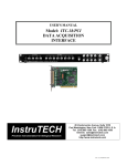
USER’S MANUAL
Model: ITC-18/PCI and ITC-18/USB
DATA ACQUISITION INTERFACE WITH PCI OR USB
HOST ADAPTER
InstruTECH
Precision Instrumentation for Biological Research
20 Vanderventer Avenue, Suite 101E
Port Washington, New York 11050-3752 U. S. A.
Tel: (516) 883-1300 Fax: (516) 883-1558
Internet: [email protected]
[email protected]
http://www.instrutech.com/
Rev: 13, 12/14/2005 2:31 PM
INSTRUTECH CORPORATION
ITC-18/PCI AND ITC-18/USB USER’S MANUAL
Table of Contents
Table of Contents ........................................................................................................................ 2
Table of Figures .......................................................................................................................... 4
Credits ......................................................................................................................................... 5
1 General Information ................................................................................................................ 6
1.1 Product intended usage ............................................................................................ 6
1.2 Accessories............................................................................................................... 6
1.3 Unpacking ................................................................................................................ 6
1.4 Purchase Information ............................................................................................... 8
1.5 Technical Specifications .......................................................................................... 9
1.6 Description ............................................................................................................... 11
1.7 Explanation of symbols............................................................................................ 15
2 Controls and Functions ........................................................................................................... 16
2.1 Front Panel Controls ................................................................................................ 16
2.2 Rear Panel Controls ................................................................................................. 18
3 Installation............................................................................................................................... 20
3.1 Hardware installation - USB version ....................................................................... 20
3.2 Hardware installation – PCI version ........................................................................ 20
4 Important considerations......................................................................................................... 22
4.1 Warm up................................................................................................................... 22
4.2 Differential analog to digital inputs ......................................................................... 22
5 Troubleshooting ...................................................................................................................... 23
6 Additional Software ................................................................................................................ 24
6.1 Available Driver Software ....................................................................................... 24
6.2 Igor XOP’s ............................................................................................................... 24
2
INSTRUTECH CORPORATION
ITC-18/PCI AND ITC-18/USB USER’S MANUAL
7 Product Upgrades .................................................................................................................... 25
7.1 USB-18 adaptability................................................................................................. 25
7.2 PCI-18 adaptability .................................................................................................. 25
8 Product Registration................................................................................................................ 26
8.1 Why Register your purchase? .................................................................................. 26
8.2 How to Register your purchase................................................................................ 26
9 Rear Panel Connector PIN Assignments ................................................................................ 27
9.1 VR-10/100 Digital Data Recorder Connector.......................................................... 27
9.2 Serial I/O Connector ................................................................................................. 28
9.3 Current Driver Out Connector .................................................................................. 28
9.4 Digital I/O and Sequence Out Connector ................................................................. 29
9.5 Auxiliary Output Connector...................................................................................... 30
9.6 USB-18 Asynchronous Digital I/O Connector ......................................................... 31
10 Warranty Information............................................................................................................ 32
10.1 Limited Warranty ................................................................................................... 32
10.2 Obtaining Warranty Service................................................................................... 32
3
INSTRUTECH CORPORATION
ITC-18/PCI AND ITC-18/USB USER’S MANUAL
Table of Figures
FIGURE 1. EXPLANATION OF SYMBOLS .......................................................................................................... 15
FIGURE 2: ITC-18 FRONT PANEL CONTROLS ............................................................................................... 16
FIGURE 3: ITC-18 REAR PANEL CONTROLS ................................................................................................. 18
FIGURE 4: ITC-18 CURRENT DRIVER OUT EXTERNAL CONNECTIONS ......................................................... 19
FIGURE 5: ITC-18 VR-10/VR-100 CONNECTOR PINS ................................................................................... 27
FIGURE 6: ITC-18 SERIAL PORT CONNECTOR PINS ...................................................................................... 28
FIGURE 7: ITC-18 CURRENT DRIVER OUT CONNECTOR PINS ...................................................................... 28
FIGURE 8: ITC-18 DIGITAL I/O AND SEQUENCER OUT CONNECTOR PINS................................................... 29
FIGURE 9: ITC-18 AUXILIARY OUTPUT CONNECTOR PINS ............................................................................ 30
4
INSTRUTECH CORPORATION
ITC-18/PCI AND ITC-18/USB USER’S MANUAL
Credits
Instrutech Corporation would like to thank the following individuals who have contributed
their time and ideas to the development and testing of the ITC-18 computer interface:
Dr. Fred Sigworth, Yale University
Dan Brown, Bruxton Corporation
Dr. Hubert Affolter, Heka electronik
5
INSTRUTECH CORPORATION
ITC-18/PCI AND ITC-18/USB USER’S MANUAL
1 General Information
1.1 Product intended usage
The Instrutech ITC-18/USB or ITC-18/PCI is intended for research use only in a laboratory
by persons trained in its use. Users are expected to be able to properly operate the
ITC-18/USB or ITC-18/PCI and associated instruments.
The Instrutech ITC-18/USB or ITC-18/PCI is not intended for medical use. The Instrutech
ITC-18/USB or ITC-18/PCI is not intended for use in life support situations, or in
situations were improper operation or failure of the ITC-18/USB or ITC-18/PCI can result
in personal injury.
Instrutech Corporation makes no representation that the design, implementation, testing, or
manufacture of the ITC-18/USB or ITC-18/PCI meet reasonable standards for use as a
medical product.
As stated in the Instrutech Limited Warranty Statement, supplied with each product,
“Instrutech Corporation expressly disclaims all warranties to buyer except the limited
warranty set forth above, including without limitation to any and all implied warranties of
merchantability and fitness for a particular purpose.”
1.2 Accessories
The following items should have been packed with your ITC-18/USB or ITC-18/PCI
Computer Interface:
1 Power cord, 110 volt or 220 volt type depending on application
1 ITC-18 Computer interface
1 USB-18 or PCI-18 or PCI-18V3 host interface adapter
1 SC-18/12 Cable assembly (USB version only)
1 SC-18 Cable assembly (PCI version only)
1 four
foot USB Cable assembly (USB version only)
1 ITC-18 Warranty card
1 USB-18 or PCI-18 or PCI-18V3 Warranty card
1 User’s manual
If any of these items are missing please contact Instrutech Corporation immediately.
1.3 Unpacking
After unpacking the ITC-18 and accessories from the shipping carton, please inspect each
piece for any signs of shipping damage. Please contact the delivering carrier and
6
INSTRUTECH CORPORATION
ITC-18/PCI AND ITC-18/USB USER’S MANUAL
Instrutech Corporation immediately if there is any damage. Do not dispose of the shipping
carton. The carrier will want to examine the shipping carton to process a damage claim.
Instrutech Corporation insures all shipments to cover shipping damage. It is also advisable
to keep the shipping carton in the event that the instrument must be returned for service.
Use caution when removing the PCI-18 or PCI-18V3 computer plug-in card from the
special static shielding bag that it is packed in. This board is susceptible to damage and
degradation by static discharges. Do not remove the board from this static protection until
you are ready to install it into the computer. Touch the computer chassis to equalize the
static charge between yourself and the computer chassis before handling the computer
board. Following these steps is extremely important to prevent damage to the computer
interface card. Instrutech Corporation does not warranty the PCI-18 or PCI-18V3
computer card from damage caused by improper handling.
7
INSTRUTECH CORPORATION
ITC-18/PCI AND ITC-18/USB USER’S MANUAL
1.4 Purchase Information
Take the time now, while getting started, to record some purchase information here. This
will make it easier to locate this information should this become necessary in the future.
Date of purchase: .......................................... ___________________________________
Dealer: ........................................................... ___________________________________
Dealer telephone number: ............................. ___________________________________
Dealer fax number:........................................ ___________________________________
Dealer email address: .................................... ___________________________________
Contact name at dealer:................................. ___________________________________
ITC-18 Serial number: .................................. ___________________________________
USB-18 Serial number: ................................. ___________________________________
PCI-18 Serial number: .................................. ___________________________________
PCI-18V3 Serial number:.............................. ___________________________________
Other notes:
_______________________________________________________________________
_______________________________________________________________________
_______________________________________________________________________
_______________________________________________________________________
_______________________________________________________________________
_______________________________________________________________________
_______________________________________________________________________
_______________________________________________________________________
_______________________________________________________________________
_______________________________________________________________________
_______________________________________________________________________
_______________________________________________________________________
_______________________________________________________________________
_______________________________________________________________________
_______________________________________________________________________
_______________________________________________________________________
_______________________________________________________________________
8
INSTRUTECH CORPORATION
ITC-18/PCI AND ITC-18/USB USER’S MANUAL
1.5 Technical Specifications
Unless otherwise noted ambient temperature = 25 degrees Celsius
♦ Analog Input Channels:
Number of channels
8, differential, optically isolated
Type of ADC
successive approximation
Input connector
BNC on front panel
Resolution
18-bit converter, 16-bit data (1 in 3200)
Acquisition rate
200 kHz aggregate
Input range
-10.24 to +10.239 Volts
Aperture delay
10 ns
Aperture jitter
50 ps rms
Conversion speed
software selectable, 5 µs to 82 ms in 1.25 µs steps
Differential nonlinearity
+0.002% of FSR
Drift
+50 ppm/ °C
Input impedance
1MΩ
Signal-to-noise ratio
+90dB
Crosstalk
<1 LSB
♦ Programmable Gain:
Gain
software selectable, instrumentation grade 1, 2, 5,or 10V/V
Settling time
3.5 µs to 0.01% all gains
Nonlinearity
+0.0003% of FSR
Max. input voltage
+40 Volts
Input CMRR
100dB
♦ Digital Inputs:
Digital inputs
16, logic level, optically isolated
Input type
CMOS logic compatible
Operational mode
software selectable, level sense or latching. Latched mode will
hold the value until read by the software. Level sensing will change with
all level transitions.
Active high or active low
Minimum pulse width
150 ns for either operational mode
Input connectors
bits (0 to3) on front panel BNC, 16 bits on rear panel multi-pin
connector
Max. input voltage
+40 Volts
♦ Triggers:
Input
9
INSTRUTECH CORPORATION
ITC-18/PCI AND ITC-18/USB USER’S MANUAL
Number
1, hardware selectable isolated / non-isolated
Input type
CMOS logic compatible
Operational mode
software selectable, edge mode
software selectable, inverted sense
Minimum pulse width
150 ns
Input connector
BNC on front panel
Max. input voltage
+40 Volts
Output
Number
1, hardware selectable isolated / non-isolated
Output driver
AC, HCT, ACT, HCT, VCT, or 8 TTL loads
Output connector
BNC on front panel
Max. output current
6 mA
♦ Analog Outputs:
Number of channels
4,pseduo-differential, optically isolated
Type of DAC
double buffered, multiplying
Output connector
BNC
Resolution
18-bit converter, 16-bit data (1 in 65536)
Output Range
-10.24 to +10.239 volts
Conversion speed
software selectable, 5 µs to 82 ms
Gain error
0.2% of FSR
Gain linearity
<2dB
Gain drift
+25 ppm of FSR/ °C
Signal-to-noise ratio
116dB
Output impedance
200Ω (for output overload protection)
Short circuit to ground
indefinite
Output load current
+8 mA typical
♦ Digital Outputs:
Standard
Number
32, optically isolated
Output driver
AC, HCT, ACT, HCT, VCT logic compatible, or 8 TTL loads
Output connector
bits (0 to 3) on front panel BNC 32 bits on rear panel multi-pin
connector
High current drive
Number
14, optically isolated
Output driver
AC, HCT, ACT, HCT, VCT logic compatible or 8 TTL loads max
Output connector
14 bits on rear panel DB-25 multi-pin connector
10
INSTRUTECH CORPORATION
Output sink current
ITC-18/PCI AND ITC-18/USB USER’S MANUAL
350mA maximum for each bank of 7 outputs
Asynchronous outputs
Number
16, non-isolated
Output driver
HC logic compatible
Output connector
34 pin multi-pin connector
Sequencer outputs
Number
7, optically isolated
Output driver
AC, HCT, ACT, HCT, VCT logic compatible, or 8 TTL loads
Output connectors
7 bits on rear panel multi-pin connector
♦ USB host interface:
The USB-18 host interface is a USB 2.0 Hi-speed adapter that interfaces the ITC-18 rack unit to a host
computer that has USB 2.0 Hi-speed ports. The USB-18 will interface with slower USB ports but
performance will be diminished.
♦ PCI host interface:
The PCI-18 PCI interface card is a 5 volt, slave PCI host card that interfaces the ITC-18 rack unit to the
host computer.
The PCI-18V3 PCI interface card is a 3.3 volt, slave PCI host card that interfaces the ITC-18 rack unit
to the host computer.
♦ FIFO memory:
Standard:
1024 kilosample FIFO
♦ External Clock:
Optional 12.8 megahertz external clock will synchronize multiple ITC-18 interfaces.
♦ Dimensions:
W: 19", H: 1.75", D: 10.5", Weight: 8 pounds
W: 47.5 cm, H: 4.375 cm, D: 26.25 cm, Weight: 3.6 kg
♦ Power requirements:
85-264VAC 47-440 Hz 15 Watts.
♦ Warranty:
Two years parts and labor.
All technical specifications are nominal conditions and are subject to change without notice.
1.6 Description
The ITC-18 is the second generation computer interface from Instrutech Corporation. The
ITC-18 offers increased capability while retaining all of the exceptional features of it’s
predecessor, the ITC-16. The ITC-18 advances data acquisition to a new level!
11
INSTRUTECH CORPORATION
ITC-18/PCI AND ITC-18/USB USER’S MANUAL
Hardware Configuration:
The ITC-18 is a rack-mountable unit. It has BNC connectors for the analog inputs
and outputs and ribbon-cable connectors for the digital lines.
The ITC-18 is connected to a host computer over a shielded cable to a host
interface. Host interfaces are available for 3.3 and 5Volt PCI bus and USB 2.0.
The PCI and USB host interfaces are compatible with both Macintosh and PC
compatible computers. Moving the ITC-18 from one platform to another is a
simple matter of installing the proper operating system drivers.
This configuration is unique to data acquisition units. Most data acquisition
devices are printed circuit-boards installed directly in the computer itself. The
interior of a computer is an electrically noisy environment. At the very high speeds
of modern computers, even a short length of a conductive trace on a PC board acts
as an antenna. Certain kinds of data acquisition devices are not affected by such
noise (e.g. slow-speed integrating A/D converters), but high-speed high-resolution
A/D and D/A converters like the ones used in the ITC-18 are affected by such
noise. Mounting the electronics in an external box is the most effective way of
reducing this noise.
Optical Isolation:
The analog electronics of the ITC-18 are optically isolated from the digital
electronics and the computer. This provides complete electrical isolation between
the computer and the measurement.
The optical isolation is provided to eliminate computer electrical noise from the
analog measurements. Computers contain digital electronics that switch at high
speed, producing large electrical transients. The computer ground functions as the
return path for these transients, resulting in substantial high-frequency ground
noise. The ITC-18 has a completely separate analog ground that is isolated from
the computer ground. Computer ground noise is not coupled into the measurement.
Optical isolation is almost essential if low-noise analog outputs are provided. If the
analog outputs are not electrically isolated from the computer ground, the analog
output ground will contain computer-generated noise. This is one of the major
ways by which computer-generated noise is introduced into a measurement system.
The optical isolation of the ITC-18 brings with it another benefit that simplifies
complex measurement systems. Since the analog inputs and outputs of the ITC-18
float with respect to ground, the ITC-18 and computer are not a source of ground
loop problems.
Analog Circuitry:
The ITC-18 provides eight 18-bit A/D converters that feature individually
programmable input range of +1, +2, +5, or +10 volts. Using separate A/D
converters for each analog input channel eliminates crosstalk between channels and
improves the frequency response of the analog inputs.
12
INSTRUTECH CORPORATION
ITC-18/PCI AND ITC-18/USB USER’S MANUAL
Typical data acquisition devices use a single A/D converter with a multiplexer to
select between input channels. The multiplexer, usually an integrated circuit, is a
single point where all analog input signals connect. Crosstalk, both from the
multiplexer itself and from closely-spaced printed-circuit board traces, causes
signals appearing at one analog input to appear at other inputs as well. The amount
of crosstalk is usually frequency- dependent. High-frequency signals can be
affected significantly.
The ITC-18 design is particularly important when making measurements using
multiple high-frequency signal sources and analyzing the signals for correlation.
An added benefit to the ITC-18 design is that all analog inputs can be sampled
simultaneously. This simplifies analysis of high-frequency correlation between
signals, since there is no time offset between sample points on the input channels.
The ITC-18 provides four 18-bit D/A converters that feature high accuracy with
less than 1 bit (~300 microvolt) of noise.
The ITC-18 can access the A/D, D/A and digital I/O channels in any sequence.
This provides the ability of different sampling rates for each channel.
Digital I/O
The ITC-18 provides sixteen digital inputs, thirty-two digital outputs, seven
sequence RAM trigger outputs and fourteen asynchronous non-isolated digital
outputs. The digital input channels feature level sensitive or latched modes. For
maximum versatility the inputs can be inverted, allowing rising or falling edge
triggering. Thirty-two digital output channels in two banks of sixteen, with
fourteen channels paralleled with current sink circuitry for driving perfusion
valves, solenoids, or other devices directly. Seven programmable trigger outputs
for triggering from any location in the scanning sequence RAM and fourteen
asynchronous auxiliary digital outputs that can be updated at any time regardless of
the ITC-18's acquisition state are available.
FIFO Memory:
The ITC-18 is supplied with a large 1024 kilosample FIFO memory for input and
output data. The ITC-18 allows data acquisition to be performed independent of
the activity of the host computer. A large FIFO memory allows for increased
acquisition speed while minimizing the use of computer resources.
Specialized Applications
The ITC-18 uses programmable gate arrays that allow the internal hardware to be
altered for specialized applications. One available application is the Artificial
Synapse Dynamic Clamp. The clamped cell is connected to an A/D input via a
Voltage Clamp amplifier. The stimulus is computed, based on voltage measured
from the cell, lookup tables for excitation, inhibition and conductance values and
other parameters. This stimulus is applied to the cell via the current input of the
Voltage Clamp amplifier.
13
INSTRUTECH CORPORATION
ITC-18/PCI AND ITC-18/USB USER’S MANUAL
The ITC-18 implements Dynamic Clamp in hardware rather than in software. In
this Dynamic Clamp configuration the ITC-18 samples four co-phase A/D channels
at 50 kHz (20 ms), performs the necessary calculations and drives the outputs. All
calculations are done within one sample clock, resulting in an input to output delay
of only 20 ms.
Software Support
The ITC-18 has extensive software support. Software drivers are available for
Windows 3.x, Windows 95/98, Windows NT, Windows 2000, Windows XP,
MacOS classic, MacOS X, Linux, National Instruments LabView, and for
Wavemetrics IGOR Pro (XOP’s). Software packages that support the ITC-18 are
ECELL from Instrutech; PatchMaster, Pulse, X-Chart and TIDA from Heka
Elektronik; Acquire and Device Access from Bruxton Corporation; AxoGraph from
Axon Instruments; PulseControl XOP’s from Dr. Bookman and Strathclyde
WinWCP. Many custom applications have also been written for the ITC-18.
The ITC-18 costs more than low-cost data acquisition devices, which are built as printed
circuit boards mounted in a computer, without electrical isolation and multiplexing a single
A/D converter. For this extra cost, it provides a major improvement in the quality of
acquired data, making measurements possible that would not otherwise be feasible.
14
INSTRUTECH CORPORATION
ITC-18/PCI AND ITC-18/USB USER’S MANUAL
1.7 Explanation of symbols
Symbol
Description
Alternating current
Currant alternatif
Wechselstrom
Corriente alterna
Corrente variabile
On (Supply)
Allumé (alimentation)
An (Netz)
Encendido (suministro)
Sotto tensione
Off (Supply)
Éteint (alimentation)
Aus (Netz)
Apagado (suministro)
Fuori tensione
Caution
Attention
Vorsicht
Cuidado
Cautela
Protective conductor terminal
Borne du conducteur de protection
Schutzleiterpol
Terminal de conductor protector
Morsetto di filo di protezione
Figure 1. Explanation of symbols
15
INSTRUTECH CORPORATION
ITC-18/PCI AND ITC-18/USB USER’S MANUAL
2 Controls and Functions
2.1 Front Panel Controls
Circled numbers reference to the diagram of the front panel.
1
DAC OUTPUT
0
1
2
3
0
1
2
3
4
POWER
5
6
7
SIGNAL
GROUND
ITC-18 COMPUTER INTERFACE INSTRUTECH Corporation, Great Neck, N.Y. USA
4
3
8
TTL INPUT
ADC INPUT
READY
2
6
5
0
1
2
TTL OUTPUT
3
0
1
3
2
7
TRIG IN
TRIG OUT
9
Figure 2: ITC-18 Front Panel Controls
1 READY indicator:
The ready indicator will be illuminated when the ITC-18 has been properly
initialized by the host computer and the acquisition software. If this indicator is
not illuminated then the ITC-18 cannot function properly.
2 POWER indicator:
The power indicator will be illuminated when the ITC-18 has been powered on.
The ITC-18 uses circuitry that will automatically switch the internal power
supply when the computer is started or shutdown. Provided that the ITC-18 is
connected to either the PCI or USB host adapter.
3 DAC outputs:
Four BNC connectors provide access to the four individual deglitched 18-bit
(16-bit data) digital to analog converter outputs. All DAC outputs are
thermally stabilized to reduce drift. The digital to analog converter output
voltage and timing are controlled by the acquisition software. The DAC
channels have an output range of -10.24 to +10.239 volts. These channels are
optically isolated from the computer. Note: Allow a 20 to 30 minute warm-up
time for proper thermal regulation after initial power-up.
16
INSTRUTECH CORPORATION
ITC-18/PCI AND ITC-18/USB USER’S MANUAL
4 ADC inputs:
Eight BNC connectors provide access to the eight individual 18-bit (16-bit
data) analog to digital converter input channels. Each A/D channel uses a high
speed programmable gain instrumentation amplifier to provide individually
selectable gain. Analog to digital converter channel selection and sampling
interval timing is controlled by the acquisition software. The ADC channels
have an input range of -10.24 to +10.239 volts. These channels are optically
isolated from the computer. These channels are differential inputs. If the BNC
connector shield is left unconnected unexpected results can occur. Use only
high quality 75 ohm BNC cables for optimal results. The absolute maximum
input range for these inputs is ±40 volts. Do not exceed this level or damage
can result to the input circuitry.
5
SIGNAL GROUND connector:
A 3 mm banana receptacle provides connection to the internal analog ground.
This low noise ground is provided for connecting to the recording amplifier.
This ground connection is not connected to the ITC-18 case or to the computer
power supply ground. . If desired, the user should provide an external
connection between the case and the instrument rack. The mating plug for this
connector is a Keystone Electronics Corporation part number 6077.
6 TTL digital inputs:
Four BNC connectors provide access to four out of the sixteen digital input
channels. The digital input channels are controlled by the acquisition software.
These digital input channels accept standard TTL levels (5 volts and 0 volts).
These channels are optically isolated from the computer. The absolute
maximum voltage range for these inputs is -0.5 volts to +5.5 volts. Do not
exceed this range or damage can result to the input circuitry.
7 TTL digital outputs:
Four BNC connectors provide access to four out of the sixteen digital output
channels. The status of the digital output channels are controlled by the
acquisition software. These digital channels output standard TTL levels (5
volts and 0 volts). These channels are optically isolated from the computer.
These channels are optimized to drive 75 ohm BNC cables into an AC, HC,
ACT, HCT or 8-TTL load.
8 TRIG IN:
A BNC connector provides access to the external trigger input. A TTL trigger
pulse can be given to start data acquisition. The ITC-18 will be triggered with a
positive logic pulse with a minimum duration of 150ns. This input is not
isolated. The absolute maximum voltage range for this input is -0.5 volts to
+5.5 volts. Do not exceed this range or damage can result to the input
circuitry.
17
INSTRUTECH CORPORATION
ITC-18/PCI AND ITC-18/USB USER’S MANUAL
9 TRIG OUT:
A BNC connector provides access to the sequencer out data bit 0. This
sequence bit will switch with each timer period and does not use a time slot.
Can be used as a gate output signal for triggering a scope or other instrument
when data acquisition has started. The true functionality of this output is
software dependent. This output is not isolated.
2.2 Rear Panel Controls
9
20 mm type F 2 A
Fuse
FUSE
CURRENT DRIVER OUT
100 - 240 V
3AG type F 1/8 A
Fuse
AUX OUTPUTS
DIGITAL I/O and SEQUENCER OUTPUTS
EXT CLK
HOST COMPUTER
NON-ISOLATED
FUSE
IN
1 2
3
4
5
6
7
Figure 3: ITC-18 Rear Panel Controls
1 FUSE:
Replace fuse with a standard 20 mm type F 2A fuse only. Littelfuse
#217002
!
2 POWER CONNECTOR:
Accepts standard three wire IEC female type power cords. The
appropriate power cord will be provided with the ITC-18. The ITC-18
will function with a line voltage from 88 to 264 volts AC. Acceptable
line frequencies are from 47 hertz to 440 hertz. The maximum power
used by the ITC-18 is fifteen watts. WARNING: To avoid a shock
hazard, the ITC-18 must be plugged into a properly grounded
receptacle.
3 CURRENT DRIVER OUT:
DB-25 female connector. The ITC-18 provides 14 digital output channels that
can be used either as standard TTL levels or as current sink. To use as current
sink channels the connections to the external device is as follow:
18
INSTRUTECH CORPORATION
ITC-18/PCI AND ITC-18/USB USER’S MANUAL
DIGITAL I/O and SEQUENCER OUTPUTS EXT CLK
CURRENT DRIVER OUT
FUSE
SERIAL I/O
HOST COMPUTER
VR-10/VR-100
FUSE
100 - 240 VOLTS
IN
ClampA
Relay
Digital Output
Ground
+
-
Power
Supply
Maximum power supply voltage 50 Volts
Valve
etc
Note: The current sink grounds are fuse protected in case
current is fed back to the ITC-18 interface. A low-impedance
connection should be made if a common-ground external power
supply is used. As shown maximum drive current is 350 mA.
Figure 4: ITC-18 Current Driver Out external connections
4 FUSE:
Current driver out ground fuse. This fuse will open when current is fed back
into the ITC-18. Replace fuse with a standard 1.5 inch type F 1/8A fuse only.
5 DIGITAL I/O & SEQUENCE OUTPUTS:
Dual 50 pin IDC connector. 16 Digital input lines with individual grounds, 16
Digital output lines with individual grounds (Channel 0), 16 Digital output lines
with individual grounds (Channel 1) and 7 sequencer outputs with individual
grounds. Please note that the absolute maximum voltage range for the digital
inputs is -0.5 volts to +5.5 volts. Do not exceed this range or damage can
result to the input circuitry.
6 EXT CLK: (optional)
BNC connector. The external clock option allows multiple ITC-18 interfaces to
be synchronized by an external master clock. Please contact Instrutech or your
dealer for availability and specifications. If this option is installed, the absolute
maximum voltage range for this input is ±4 volts peak. Do not exceed this
range or damage can result to the input circuitry.
7 HOST COMPUTER:
80 pin high density connector. Connection to one of the ITC-18 host interface
adapters. Currently the PCI-18, PCI-18V3 or USB-18.
9 AUX. OUTPUTS:
34 pin IDC connector. 16 auxiliary output lines with individual grounds.
These signals are not isolated and must use the non-isolated ground provided on
this connector for proper operation.
19
INSTRUTECH CORPORATION
ITC-18/PCI AND ITC-18/USB USER’S MANUAL
3 Installation
3.1 Hardware installation - USB version
1. Install the ITC-18 interface into the operating position. Make sure that the
interface can reach the computer with the supplied cable. Do not extend this cable.
Unreliable operation can result if this cable is extended.
2. Install the SC-12 cable between the ITC-18 interface labeled “HOST
COMPUTER” and the USB-18 labeled “To ITC-18”. The connectors on either
end of the cable are keyed and will only mate when properly inserted. Fix the
connectors in place with the screws attached to the connector. This is important to
ensure a good electrical contact.
3. Install the USB cable to the USB-18 labeled “To USB” and an available USB 2.0
Hi-speed port on the computer.
4. Connect the power cord to the ITC-18. The internal power supply used in the
ITC-18 is an auto switching multi-voltage supply that will operate
from 100 volts to 260 volts. Make sure that the ITC-18 power cord
is plugged into a properly grounded AC receptacle. Improper
grounding of the ITC-18 could result in an electrical shock hazard.
It is advisable to plug all equipment into a common outlet strip, this
will minimize power line induced noise in the system. Equipment
plugged into different outlets can cause excessive sixty hertz noise
to be induced into the acquired data.
!
5. Before powering up please recheck all connections. If all connections are proper
then the power led will illuminate once the computer is started.
6. You are now ready to power up the system and install the driver software. The
ITC-18/USB is supported on Apple MacOS X (10.2 and above) and Windows NT,
2000 and XP. Download the appropriate driver installer from our web site,
www.instrutech.com. Follow the installation instructions provided with the
acquisition software that will be used with this ITC-18/USB interface.
3.2 Hardware installation – PCI version
1. Turn the computer OFF.
2. Disconnect the power cord to the computer.
3. Remove the cover from the computer to access the computer’s PCI expansion slots.
Please follow the instructions outlined in your computer user’s manual for
removing the cover of the computer. Locate an empty PCI bus slot and remove the
cover over the case access opening. Use caution here to guard against static, as
outlined in chapter one. Remove the PCI-18 or PCI-18V3 card from the static
shielding packaging. Line up the card-edge connector on the PCI board with the
female connector on the CPU board. Gently press the two together until fully
20
INSTRUTECH CORPORATION
ITC-18/PCI AND ITC-18/USB USER’S MANUAL
seated. If any resistance is felt please check for any proper alignment of the
connectors. Do not force the two boards together. It should take minimal pressure
to mate the two connectors. If excessive force is used here, damage could result to
the PCI card and the computer main board. If your model computer uses a screw to
secure the expansion cards in place, install the screw and make sure that it is
fastened securely. Note: On some model computers the rear bracket may not line
up correctly against the inside of the computer case. For these computers, loosen
the two screws on the PCI card that hold the rear bracket in place. Adjust the
bracket for a better fit and re-tighten the screws.
4. Re-install the cover of the computer.
5. Install the ITC-18 interface into the operating position. Make sure that the
interface can reach the computer with the supplied cable. Do not extend this cable.
Unreliable operation can result if this cable is extended.
6. Install the SC-18 cable between the ITC-18 interface and the PCI computer board.
The connectors on either end of the cable are keyed and will only mate when
properly inserted. Fix the connectors in place with the screws attached to the
connector. This is important to ensure a good electrical contact.
7. Connect the power cord to the ITC-18. The internal power supply used in the
ITC-18 is an auto switching multi-voltage supply that will
operate from 100 volts to 260 volts. Make sure that the ITC-18
power cord is plugged into a properly grounded AC receptacle.
Improper grounding of the ITC-18 could result in an electrical
shock hazard. It is advisable to plug all equipment into a
common outlet strip, this will minimize power line induced noise
in the system. Equipment plugged into different outlets can
cause excessive sixty hertz noise to be induced into the acquired
data.
!
8. Before powering up please recheck all connections. If all connections are proper
then the power led will illuminate once the computer is started.
9. You are now ready to power up the system and install the driver software. The
ITC-18/PCI is supported on MacOS Classic, MacOS X (10.2 and above), Windows
9x, ME, NT, 2000, XP and Linux. Download the appropriate driver installer from
our web site, www.instrutech.com. Follow the installation instructions provided
with the acquisition software that will be used with this ITC-18/PCI interface.
21
INSTRUTECH CORPORATION
ITC-18/PCI AND ITC-18/USB USER’S MANUAL
4 Important considerations
4.1 Warm up
The ITC-18 digital to analog converter circuitry uses a sophisticated thermal stabilization
technique to provide complete stability of the DAC outputs over time. For optimal
stability of the DAC outputs the ITC-18 requires 20 to 30 minutes of warm up time.
During this initial 20 minutes after the ITC-18 is turned on, DAC drift will occur. This
drift can be as large as 6 mV during the initial warm up period. After this warm-up period
the DAC outputs will be extremely stable.
4.2 Differential analog to digital inputs
The ITC-18 analog to digital converter inputs are true differential inputs. For proper
operation of the A/D converter the cable connecting the A/D input to the signal source
must have a complete shield. High quality 75 ohm BNC to BNC cables are recommended
for optimum performance.
A connection should be made between the SIGNAL GROUND connector on the ITC-18
front panel to the signal ground connector on the signal source. Most patch clamp
amplifiers provide a suitable connection point for the signal ground.
22
INSTRUTECH CORPORATION
ITC-18/PCI AND ITC-18/USB USER’S MANUAL
5 Troubleshooting
Most problems arise from incorrect installation of the hardware, and/or incorrect use of the
software. The first thing to check is for proper installation of the hardware interface.
Check the Instrutech website for a newer version of the driver. At times we make changes
based on operating system changes, enhancements or bug fixes.
Check to see that the AC line cord is plugged in correctly.
Check the fuses on the ITC-18 interface rear panel.
Check the cable connecting the PCI card or the USB host to the ITC-18 interface. Make
sure both ends are plugged in securely and that the cable is not damaged.
Check the USB cable connecting the USB-18 and the host computer. Make sure both ends
are plugged in securely and that the cable is not damaged.
Make sure that the computers USB port is USB 2.0 Hi-speed.
If all of the above steps fail to resolve the problem then contact your dealer for assistance.
23
INSTRUTECH CORPORATION
ITC-18/PCI AND ITC-18/USB USER’S MANUAL
6 Additional Software
6.1 Available Driver Software
Instrutech Corporation has available driver software for researchers and developers who
wish to write custom applications using the ITC-18 Interface. These drivers and
appropriate manuals are available in both MacOS and Windows formats. They are
available from Instrutech Corporation by request. They are also available from Instrutech
Corporation by Internet WWW, or email. For access to our WWW site our URL is
http://www.instrutech.com/. By email send a message to [email protected]. If you
do not have access to the Internet, call Instrutech and request the ITC driver disk for the
operating system of your choice.
6.2 Igor XOP’s
Instrutech Corporation has available an XOP for Wavemetrics Igor that will allow
researchers and developers to write custom applications using the ITC-18 Interface and
Wavemetrics Igor software. This XOP and the appropriate manual is available from
Instrutech Corporation by request. It is also available from Instrutech Corporation by
Internet WWW, or email.
For access to our WWW site our URL is
http://www.instrutech.com/. By email send a message to [email protected]. If you
do not have access to the Internet, call Instrutech and request the ITC-18 XOP diskette.
24
INSTRUTECH CORPORATION
ITC-18/PCI AND ITC-18/USB USER’S MANUAL
7 Product Upgrades
7.1 USB-18 adaptability
The USB-18 card is designed to be firmware upgradeable by users, should this ever
become necessary to keep up with new developments in the specification for the USB bus.
Do not attempt to do such an upgrade without the approval of Instrutech Corporation or
one of its authorized agents. If this upgrade is performed improperly, the USB-18 card
will malfunction and become unusable.
First you must acquire the proper upgrade software from Instrutech Corporation or one of
its representatives. These upgrades will be announced on our Web site. Update software
will be made available in MacOS and Windows formats. After the software is run is
should give you a successful completion message. The USB-18 should then be unplugged
from the USB port and then reconnected. The update has now been completed.
7.2 PCI-18 adaptability
The PCI-18/PCI-18V3 card is designed to be firmware upgradeable by the user, should this
ever become necessary to keep up with new developments in the specification for the PCI
bus. Do not attempt to do such an upgrade without the approval of Instrutech Corporation
or one of its authorized agents. If this upgrade is performed improperly, the PCI-18 or
PCI-18V3 card will malfunction and become unusable.
First you must acquire the proper upgrade software from Instrutech Corporation or one of
its representatives. These upgrades will be announced on the Instrutech Web site. The
cover of the computer must be removed to access the PCI card in order to install a jumper.
A programming jumper needs to be installed across the pins labeled “WE”. Install this
shunt with the computer powered off. After this shunt is installed power on the computer
and run the software for your system. Update software will be made available in MacOS
and Windows formats. After the software is run is should give you a successful
completion message. The computer should then be powered down and the jumper
removed from the “WE” pins. Close the computer and turn the power back on. The
update has now been completed.
If there is any difficulty in this process, please contact your dealer.
25
INSTRUTECH CORPORATION
ITC-18/PCI AND ITC-18/USB USER’S MANUAL
8 Product Registration
8.1 Why Register your purchase?
Instrutech Corporation periodically offers enhancements and updates to our products.
Without product registration, users of our products may miss out on announcements of
important enhancements to the products that they are using.
Instrutech Corporation does not make our customer list available to anyone else. Any
information that you provide to us is strictly confidential.
8.2 How to Register your purchase
Product registration can be accomplished in two ways. You may fill out and mail in the
product registration/warranty card supplied with each Instrutech Corporation product. You
may also register on-line at our World Wide Web site at http://www.instrutech.com/.
26
INSTRUTECH CORPORATION
ITC-18/PCI AND ITC-18/USB USER’S MANUAL
9 Rear Panel Connector PIN Assignments
9.1 VR-10/100 Digital Data Recorder Connector
Below is a listing of the pin assignments of the optional VR-10/VR-100 port on the rear
panel of the ITC-18 interface. This port is optional and is not provided on standard
configuration ITC-18 units.
Pin 1
Pin 39
Pin 40
Pin 2
Figure 5: ITC-18 VR-10/VR-100 connector pins
Pin
1
3
5
7
9
11
13
15
17
19
21
23
25
27
29
31
33
35
37
39
Assignment
PPMCM0 (channel mode)
PPMCM2 (channel mode)
* no connection
* no connection
* no connection
* no connection
RSPC0 (RS-232 RxD)
Ground
PPMPLY(Play/Rec. mode)
no connection
Ground
PPMD1 (data bit 1)
PPMD3 (data bit 3)
PPMD5 (data bit 5)
PPMD7 (data bit 7)
PPMD9 (data bit 9)
PPMD1 (data bit 11)
PPMD13 (data bit 13)
PPMSTR (valid data flag)
Ground
Pin
2
4
6
8
10
12
14
16
18
20
22
24
26
28
30
32
34
36
38
40
Assignment
PPMCM1 (channel mode)
PPMARS (analog reset)
PPMCUE (CUE out)
PPMCMP (FRAME out)
Ground
RSPCI (RS-232 TxD)
Ground
Ground
Ground
Ground
PPMD0 (data bit 0)
PPMD2 (data bit 2)
PPMD4 (data bit 4)
PPMD6 (data bit 6)
PPMD8 (data bit 8)
PPMD10 (data bit 10)
PPMD12 (data bit 12
PPMERR (ERROR bit)
PPMTRG (TRIGGER bit)
Ground
* Do not ground these connections they are used by the VR-10/100.
27
INSTRUTECH CORPORATION
ITC-18/PCI AND ITC-18/USB USER’S MANUAL
9.2 Serial I/O Connector
Below is a listing of the pin assignments of the male serial port connector on the rear panel
of the ITC-18 interface. This port is optional and is not provided on standard configuration
ITC-18 units.
Figure 6: ITC-18 Serial Port connector pins
Pin
1
2
3
4
5
6
7
8
9
Assignment
RLSD: received line signal detect
RxD: receive data
TxD: transmit data
DTR: data terminal ready
Ground
DSR: data set ready
RTS: request to send
CTS: clear to send
RI: ring indicator
9.3 Current Driver Out Connector
Below is a listing of the pin assignments of the Current Driver Out connector on the rear
panel of the ITC-18 interface.
Figure 7: ITC-18 Current Driver Out connector pins
Pin
1
2
3
4
5
6
7
8
9
10
Assignment
Clamp B (bank 2)
out channel 12 (bank 2)
Ground
Ground
Ground
Ground
Ground
Ground
Ground
Ground
Pin
14
15
16
17
18
19
20
21
22
23
Assignment
out channel 13 (bank 2)
out channel 11 (bank 2)
out channel 10 (bank 2)
out channel 9 (bank 2)
out channel 8 (bank 2)
out channel 7 (bank 2)
clamp A (bank 1)
out channel 6 (bank 1)
out channel 5 (bank 1)
out channel 4 (bank 1)
28
INSTRUTECH CORPORATION
11
12
13
ITC-18/PCI AND ITC-18/USB USER’S MANUAL
Ground
out channel 2 (bank 1)
out channel 0 (bank 1)
24
25
out channel 3 (bank 1)
out channel 1 (bank 1)
9.4 Digital I/O and Sequence Out Connector
Below is a listing of the pin assignments of the Digital I/O and Sequence Out port on the
rear panel of the ITC-18 interface.
Pin 49
Pin 1
Pin 50
Pin 2
Figure 8: ITC-18 Digital I/O and Sequencer Out connector pins
Pin
1
3
5
7
9
11
13
15
17
19
21
23
25
27
29
31
33
35
37
39
41
43
45
47
49
Top Connector
Ground
TTL input bit 8
TTL input bit 9
TTL input bit 10
TTL input bit 11
TTL input bit 12
TTL input bit 13
TTL input bit 14
TTL input bit 15
TTL channel 0 bit 12
TTL channel 0 bit 13
TTL channel 0 bit 14
TTL channel 0 bit 15
TTL channel 1 bit 8
TTL channel 1 bit 9
TTL channel 1 bit 10
TTL channel 1 bit 11
TTL channel 1 bit 12
TTL channel 1 bit 13
TTL channel 1 bit 14
TTL channel 1 bit 15
sequence out 4
sequence out 5
sequence out 6
no connection
Bottom Connector
no connection
TTL input bit 0
TTL input bit 1
TTL input bit 2
TTL input bit 3
TTL input bit 4
TTL input bit 5
TTL input bit 6
TTL input bit 7
TTL channel 0 bit 8
TTL channel 0 bit 9
TTL channel 0 bit 10
TTL channel 0 bit 11
TTL channel 1 bit 0
TTL channel 1 bit 1
TTL channel 1 bit 2
TTL channel 1 bit 3
TTL channel 1 bit 4
TTL channel 1 bit 5
TTL channel 1 bit 6
TTL channel 1 bit 7
sequence out 0
sequence out 1
sequence out 2
sequence out 3
Pin
2
4
6
8
10
12
14
16
18
20
22
24
26
28
30
32
34
36
38
40
42
44
46
48
50
Top &Bottom Connector
Ground
Ground
Ground
Ground
Ground
Ground
Ground
Ground
Ground
Ground
Ground
Ground
Ground
Ground
Ground
Ground
Ground
Ground
Ground
Ground
Ground
Ground
Ground
Ground
Ground
29
INSTRUTECH CORPORATION
ITC-18/PCI AND ITC-18/USB USER’S MANUAL
9.5 Auxiliary Output Connector
Pin 1
Pin 33
Pin 34
Pin 2
Figure 9: ITC-18 Auxiliary output connector pins
Signal
Ground
Out 0
Out 1
Out 2
Out 3
Out 4
Out 5
Out 6
Out 7
Out 8
Out 9
Out 10
Out 11
Out 12
Out 13
Out 14
Out 15
Pin
1
3
5
7
9
11
13
15
17
19
21
23
25
27
29
31
33
Signal
Ground
Ground
Ground
Ground
Ground
Ground
Ground
Ground
Ground
Ground
Ground
Ground
Ground
Ground
Ground
Ground
Ground
Pin
2
4
6
8
10
12
14
16
18
20
22
24
26
28
30
32
34
30
INSTRUTECH CORPORATION
ITC-18/PCI AND ITC-18/USB USER’S MANUAL
9.6 USB-18 Asynchronous Digital I/O Connector
Below is a listing of the pin assignments of the Digital I/O port on the USB-18 host
interface adapter. The Digital I/O port is a standard 68-pin mini DIN connector (same as
SCSI cables).
Pin
1
2
3
4
5
6
7
8
9
10
11
12
13
14
15
16
17
18
19
20
21
22
23
24
25
26
27
28
29
30
31
32
33
34
Assignment
Ground
Ground
Ground
Ground
Ground
Ground
Ground
Ground
Ground
Ground
Ground
User Out
Ground
Timer Out 2
Ground
Timer Out 1
Ground
Timer Out 0
Ground
Interrupt
Ground
Timer 2
Ground
Timer 1
Ground
Timer 0
Ground
Ground
Ground
Ground
Ground
Ground
Ground
Ground
Pin
35
36
37
38
39
40
41
42
43
44
45
46
47
48
49
50
51
52
53
54
55
56
57
58
59
60
61
62
63
64
65
66
67
68
Assignment
Ground
Asynchronous TTL Out 0
Asynchronous TTL Out 1
Asynchronous TTL Out 2
Asynchronous TTL Out 3
Asynchronous TTL Out 4
Asynchronous TTL Out 5
Asynchronous TTL Out 6
Asynchronous TTL Out 7
Asynchronous TTL Out 8
Asynchronous TTL Out 9
Asynchronous TTL Out 10
Asynchronous TTL Out 11
Asynchronous TTL Out 12
Asynchronous TTL Out 13
Asynchronous TTL Out 14
Asynchronous TTL Out 15
Asynchronous TTL IN 15
Asynchronous TTL IN 14
Asynchronous TTL IN 13
Asynchronous TTL IN 12
Asynchronous TTL IN 11
Asynchronous TTL IN 10
Asynchronous TTL IN 9
Asynchronous TTL IN 8
Asynchronous TTL IN 7
Asynchronous TTL IN 6
Asynchronous TTL IN 5
Asynchronous TTL IN 4
Asynchronous TTL IN 3
Asynchronous TTL IN 2
Asynchronous TTL IN 1
Asynchronous TTL IN 0
Ground
31
INSTRUTECH CORPORATION
ITC-18/PCI AND ITC-18/USB USER’S MANUAL
10 Warranty Information
10.1 Limited Warranty
Instrutech Corporation warrants to the first purchaser, for a period of two years from the date of
purchase, that this Instrutech Instrument (hereafter referred to as the “Product”) will be free from
defective workmanship and materials, and agrees that it will, at its option, either repair the defect or
replace the defective Product or part thereof at no charge to the purchaser for parts and labor. The
Product must be returned to Instrutech Corporation, postpaid and insured. Instrutech Corporation
will return the Product, postpaid and insured, in the most appropriate method as determined by
Instrutech Corporation. If a faster shipping service is desired by the customer, any additional
special delivery expenses must be paid by the customer.
This warranty does not apply to shipping damage. Instrutech Corporation fully insures all
shipments. Any claims of damage upon receipt must be filed with the carrier and Instrutech
Corporation immediately.
This warranty does not apply to any exterior appearance item of the Product which has been
damaged or defaced, which has been subjected to misuse and abuse, abnormal service or handling,
or which has been altered or modified in design or construction.
This warranty does not apply to any interconnection cables supplied with the Product.
This warranty does not apply if any unauthorized repairs, modifications or alterations have been
made to the Product.
This warranty applies to software products only to the extent of maintenance release software to
correct improper operation of the Product. Software updates to increase the capabilities of the
present product are not to be provided under the terms of this warranty. Updates will be sent at no
cost to the customer by normal common carrier routes. If faster delivery is desired, the customer
must assume any additional expenses for special delivery service.
No sales organizations, other than Instrutech Corporation itself, are authorized to make any
warranties other than those described above, or to extend the duration of any warranties beyond the
time period described above on the behalf of Instrutech Corporation. If Instrutech Corporation
agrees to such a modification of this warranty, Instrutech will furnish a modified copy of this
agreement, which must be presented if a claim is being made under these modified terms.
10.2 Obtaining Warranty Service
Warranty service of this Product can be obtained by returning the Product, post paid and
insured, to Instrutech Corporation, or one of its sales agents. Prior authorization before
shipping the product is advised for the most expedient service.
32