1
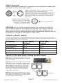
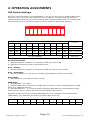
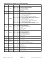
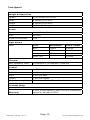
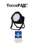
KAPTIVATOR
Blizzard Lighting, LLC
www.blizzardlighting.com
Waukesha, WI USA
Copyright (c) 2013
TABLE OF CONTENTS
Kaptivator™ 1
1. Getting Started3
What’s In The Box?3
Getting It Out Of The Box
3
Powering Up!3
Getting A Hold Of Us3
Laser Safety Requirements
4
2. Meet The Kaptivator™5
Main Features5
Laser Specifications
5
DMX Quick Reference5
The Kaptivator Pin-up Picture6
3. Setup 7
Fuse Replacement 7
Connecting A Bunch Of Kaptivators™
7
Data/DMX Cables 7
Cable Connectors 8
3-Pin??? 5-Pin??? Huh?8
Take It To The Next Level: Setting up DMX Control
8
Fixture Linking (Master/Slave Mode)
9
Mounting/Rigging9
4. Operating Adjustments 10
DIP Switch Settings 10
Sound Active Mode 10
Auto Shapes 10
Auto Animation 10
Slave Mode 10
DMX Mode 10
DMX Channel Values In-Depth11
Troubleshooting 12
5. Appendix 13
A Quick DMX Lesson13
Keeping Your Kaptivator™ As Good As New
14
Returns (Gasp!) 14
Shipping Issues14
Tech Specs
15
Kaptivator™ Manual - Rev. A Page 2
(c) 2013 Blizzard Lighting, LLC
1. GETTING STARTED
What’s In The Box?
• 1 x Kaptivator™
• 1 x Mounting bracket w/bolts
• This Lovely User Manual
Getting It Out Of The Box
Congratulations on purchasing one way cool, way original RGB 3D Laser!
Now that you’ve got your Kaptivator™ (or hopefully, Kaptivators!), you
should carefully unpack the box and check the contents to ensure that
all parts are present and in good condition. If anything looks as if it
has been damaged in transit, notify the shipper immediately and keep
the packing material for inspection. Again, please save the carton and
all packing materials. If a fixture must be returned to the factory, it is
important that the fixture be returned in the original factory box and
packing.
Powering Up!
All fixtures must be powered directly off a switched circuit and cannot
be run off a rheostat (variable resistor) or dimmer circuit, even if
the rheostat or dimmer channel is used solely for a 0% to 100%
switch.
AC Voltage Switch - Not all fixtures have a voltage select switch, so
please verify that the fixture you receive is suitable for your local power
supply. See the label on the fixture or refer to the fixture’s specifications chart for more information. A fixture’s listed current rating is its
average current draw under normal conditions. Check the fixture or device carefully to make sure that if a voltage selection switch exists that
it is set to the correct line voltage you will use.
Warning! Verify that the voltage select switch on your unit
matches the line voltage applied. Damage to your fixture may
result if the line voltage applied does not match the voltage indicated on the voltage selector switch. All fixtures must be connected to circuits with a suitable Ground (Earthing).
Getting A Hold Of Us
If something is wrong, just give us a call or send an email. We’ll
be happy to help, honest.
Blizzard Lighting
W220 N1531 Jericho Ct. Suite E, Waukesha, WI 53186 USA
[email protected]
www.blizzardlighting.com
1.866.493.6025
Kaptivator™ Manual - Rev. A Page 3
(c) 2013 Blizzard Lighting, LLC
LASER SAFETY REQUIREMENTS
Lasers are one of the coolest effects available, and when they are used appropriately, they will be fun, legal and harmless. To make sure that is the case...
• Always set up and install all laser effects so that all laser light is at least 3 meters (9.8 feet) above the floor on which people can stand.
• After setting up, and before public use, test laser to ensure proper function. Do
not use if any defect is detected. Do not use if laser emits only one or two laser
beams rather than dozens/hundreds, as this could indicate damage to the diffraction grating optic, and could allow emission of higher laser levels above Class
3R.
• NEVER point lasers at people or animals. Never look into the laser aperture or
laser beams.
• NEVER point lasers in areas in which people can potentially get exposed, such
as uncontrolled balconies, etc.
• NEVER point lasers at highly reflective surfaces, such as windows, mirrors and
shiny metal. Even laser reflections can be hazardous.
• NEVER point a laser at aircraft, this is a federal offense!
• NEVER point un-terminated laser beams into the sky.
• NEVER expose the output optic (aperture) to cleaning chemicals.
• NEVER use laser if the laser appears to emit only one or two beams.
• NEVER use the laser if the housing is damaged, the housing is open, or if the
optics appear damaged in any way.
• NEVER open the laser housing. The high laser power levels inside of the protective housing can start fires, burn skin and will cause instant eye injury.
• NEVER leave this device running unattended.
The operation of a class 3R laser show is only allowed if the show is controlled
by a skilled and well-trained operator, familiar with the data from this manual.
The legal requirements for using laser entertainment products vary from country
to country. The user is responsible for the legal requirements at the location/
country of use.
Kaptivator™ Manual - Rev. A Page 4
(c) 2013 Blizzard Lighting, LLC
2. MEET THE Kaptivator™
Main FEATURES
•
•
•
•
•
•
•
•
High power class 3B RGB laser
Sound active mode, auto mode, DMX512 (11ch) & master/slave
120 beam show and 7 animated graphic show patterns
3-pin DMX In/Out
Microphone sensitivity adjustment knob
Dipswitch contolled function settings
Polished blue aluminum casing w/hanging bracket
Compact and lightweight (it kept its new year’s resolution!)
Laser Specifications
Color
Wavelength
Power Output
Red
650nm
100mW
Green
532nm
50mW
Blue
450nm
100mW
White (all)
250mW
DMX Quick Reference - 11 Channel Mode
Channel
1
What it does
2
Pattern Select
3
Color Change
4
Moving-X
5
Moving-Y
6
Dimmer-X
7
Dimmer-Y
8
Rotation
9
Zoom (+/-)
10
Drawing
11
Rolling X/Y
Mode
Kaptivator™ Manual - Rev. A Page 5
(c) 2013 Blizzard Lighting, LLC
Figure 1: The Kaptivator™ Pin-Up Picture
Convenient
Dipswitch Chart
Secure Mounting Bracket
& Adjustment Screws
Attractive Ice Blue
Colored Aluminum Casing
Laser Output (Aperture)
Figure 2: The Rear Connections
Mic Sensitivity
On/Off Switch
Cooling Fan
Microphone
Dipswitches
Mic Indicator
DMX In
DMX Out
AC Power Input
Kaptivator™ Manual - Rev. A Page 6
Power Indicator
(c) 2013 Blizzard Lighting, LLC
3. SETUP
Fuse Replacement
With a philips head screwdriver, unscrew the fuse holder from its housing. Remove the damaged fuse from its holder and replace with exact
same type fuse. Insert the fuse holder back in its place and reconnect
power.
Connecting A Bunch of Kaptivator™ Fixtures
You will need a serial data link to run light shows using a DMX-512
controller or to run shows on two or more fixtures set to sync in master/slave operating mode. The combined number of channels required
by all the fixtures on a serial data link determines the number of fixtures the data link can support.
Fixtures on a serial data link must be daisy chained in one single line.
Also, connecting more than 32 fixtures on one serial data link without
the use of a DMX optically-isolated splitter may result in deterioration
of the digital DMX signal.
The maximum recommended cable-run distance is 500 meters (1640
ft). The maximum recommended number of fixtures on a serial data
link is 32 fixtures.
Data/DMX Cabling
To link fixtures together you’ll need data cables. You should use datagrade cables that can carry a high quality signal and are less prone to
electromagnetic interference.
For instance, Belden© 9841 meets the specifications for EIA RS-485
applications. Standard microphone cables will “probably” be OK, but
note that they cannot transmit DMX data as reliably over long distances. In any event, the cable should have the following characteristics:
2-conductor twisted pair plus a shield
Maximum capacitance between conductors – 30 pF/ft.
Maximum capacitance between conductor & shield – 55 pF/ft.
Maximum resistance of 20 ohms / 1000 ft.
Nominal impedance 100 – 140 ohms
Kaptivator™ Manual - Rev. A Page 7
(c) 2013 Blizzard Lighting, LLC
Cable Connectors
Cables must have a male XLR connector on one end and a female XLR
connector on the other end. (Duh!)
CAUTION: Do not allow contact between the common and the fixture’s chassis ground. Grounding the common can cause a ground
loop, and your fixture may perform erratically. Test cables with an
ohm meter to verify correct polarity and to make sure the pins are not
grounded or shorted to the shield or each other.
3-Pin??? 5-Pin??? Huh?!?
If you use a controller with a 5 pin DMX output connector, you will need to use a 5 pin to 3 pin adapter.
They are widely available over the internet and from specialty retailers If you’d like to build your own, the
chart below details a proper cable conversion:
Conductor
3-Pin Female
(Output)
5-Pin Male
(Input)
Ground/Shield
Pin 1
Pin 1
DMX Data (-)
Pin 2
Pin 2
DMX Data (+)
Pin 3
Pin 3
Not Used.
No Connection.
No Connection.
Not Used.
No Connection.
No Connection.
Take It To The Next Level: Setting Up DMX Control
Step 1: Connect the male connector of the
DMX cable to the female connector (output)
on the controller.
Step 2: Connect the female connector of the
DMX cable to the first fixture’s male connector (input). Note: It doesn’t matter which
fixture address is the first one connected. We recommend connecting the fixtures in
terms of their proximity to the controller,
rather than connecting the lowest fixture
number first, and so on.
Step 3: Connect other fixtures in the chain
from output to input as above. Place a DMX
terminator on the output of the final fixture
to ensure best communication.
Kaptivator™ Manual - Rev. A Page 8
(c) 2013 Blizzard Lighting, LLC
Fixture Linking (Master/Slave Mode)
1. Connect the (male) 3 pin connector side of the
DMX cable to the output (female) 3 pin connector of
the first fixture.
2. Connect the end of the cable coming from the
first fixture which will have a (female) 3 pin connector to the input connector of the next fixture consisting of a (male) 3 pin connector. Then, proceed
to connect from the output as stated above to the
input of the following fixture and so on.
A quick note: Often,
the setup for MasterSlave and Standalone
operation requires that
the first fixture in the
chain be initialized for
this purpose via either
settings in the control
panel or DIP-switches.
Secondarily, the fixtures
that follow may also require a slave setting.
Check the “Operating Adjustments” section in this manual for complete instructions for this type of setup and configuration.
Mounting & Rigging
This fixture may be mounted in any SAFE position provided there is
enough room for ventilation.
It is important never to obstruct the fan or vents pathway. Mount the
fixture using a suitable “C” or “O” type clamp. The clamp should be
rated to hold at least 10x the fixture’s weight to ensure structural stability. Do not mount to surfaces with unknown strength, and ensure
properly “rated” rigging is used when mounting fixutres overhead.
Adjust the angle of the fixture by loosening both knobs and tilting the
fixture. After finding the desired position, retighten both knobs.
• When selecting installation location, take into consideration lamp
replacement access (if applicable) and routine maintenance.
• Safety cables MUST ALWAYS be used.
• Never mount in places where the fixture will be exposed to rain,
high humidity, extreme temperature changes or restricted ventilation.
Kaptivator™ Manual - Rev. A Page 9
(c) 2013 Blizzard Lighting, LLC
4. OPERATING ADJUSTMENTS
DIP Switch Settings
All of the various functions of the Kaptivator™ are set up using the 10-position DIP switch
located on the rear of the unit. Using this set of switches, you can select the different
operating modes and also set up the starting DMX channel in DMX mode. The chart below
describes the various operating modes and their respective DIP switch settings.
ON
DIP
1
2
3
4
5
6
7
8
9
10
Dipswitch Chart
Function
#1
#2
#3
#4
#5
#6
#7
#8
#9
#10
OFF
OFF
OFF
OFF
OFF
OFF
OFF
OFF
OFF
ON
Sound Active
OFF
OFF
OFF
OFF
OFF
OFF
OFF
OFF
ON
ON
Auto - Shapes
ON
OFF
OFF
OFF
OFF
OFF
OFF
OFF
ON
ON
Auto - Animation
ON
OFF
OFF
OFF
OFF
OFF
OFF
OFF
OFF
OFF
Slave Mode
OFF
DMX Mode
Set DMX Address
Sound Active Mode
1.) Set the dipswitch numbers 1-9 settings to OFF, and #10 to ON.
2.) Adjust the sensitivity knob to the desired level.
Auto - Shapes
1.) Set the dipswitch numbers 1-8 settings to OFF, and #9 and #10 to ON.
Auto - Animation
1.) Set the dipswitch #1, #9 and #10 to ON, and dipswitch numbers 2-8 to OFF.
Slave Mode
1.) Set dipswitch #1 to ON and others to OFF.
DMX Mode
1.) Set dipswitch 10 to OFF.
2.) Connect DMX OUT of controller to DMX IN of 1st fixture. Daisy chain DMX OUT to DMX
IN for any additional fixtures.
3.) Use dipswitches 1 – 9 to set the fixtures Starting DMX Address. Each dipswitch represents a binary value in which the sum would equal the set address.
Example: To set the fixtures starting DMX address to 12, dipswitch #10 would be OFF
(DMX Mode), plus dipswitch #3 and #4 would be ON. (4+8=12).
Dipswitch
#1
#2
#3
#4
#5
#6
#7
#8
#9
#10
Value
1
2
4
8
16
32
64
128
256
ON
Kaptivator™ Manual - Rev. A Page 10
(c) 2013 Blizzard Lighting, LLC
DMX Values In-Depth (11-Channel Mode)
Channel
Function
Value
000
064
096
128
160
192
<->
<->
<->
<->
<->
<->
Description
063
095
127
159
191
255
Laser Off
Sound Active Beam Animation
Sound Active Single Animation
Auto Beam Animation
Auto Single Animation
DMX Mode
1
Mode
2
Pattern
Select
000 <-> 239
240 <-> 255
120 Static Patterns
7 Single Animation Changes
Color
Change
000
002
070
080
090
100
110
120
130
140
180
220
<->
<->
<->
<->
<->
<->
<->
<->
<->
<->
<->
<->
001
069
079
089
099
109
119
129
139
179
219
255
Laser Off
R--G--B--RG--RB--GB--RGB
R--G--B, 8 Point Display
RG--RB--RG--RGB, 8 Point Color Change
R--G--B--RG--RB--GB--RGB, 8 Point Color Change
R--G--B--RG--RB--GB--RGB, Running in Turn
R--G--B, Color Change
RG--RB--RG--RGB, Color Change
R--G--B--RG--RB--GB--RGB, Color Change
R--G--B, Auto Color Change
RG--RB--RG--RGB, Auto Color Change
R--G--B--RG--RB--GB--RGB, Auto Color Change
Moving-X
000
128
161
193
225
240
248
<->
<->
<->
<->
<->
<->
<->
127
160
192
224
239
247
255
Manual Left to Right Adjustment
Auto Left Adjustment
Auto Right Adjustment
Auto Left/Right Adjustment
Jumping
Prismatic Shape
Oblique Up
5
Moving-Y
000
128
161
193
225
240
248
<->
<->
<->
<->
<->
<->
<->
127
160
192
224
239
247
255
Manual Up to Down Adjustment
Auto Down Adjustment
Auto Up Adjustment
Auto Up/Down Adjustment
Square Tracing Movment
Square Tracing Movment
Oblique Down
6
Dimmer-X
000 <-> 150
151 <-> 255
Manual Dimmer
Auto Dimmer
7
Dimmer-Y
000 <-> 150
151 <-> 255
Manual Dimmer
Auto Dimmer
8
Rotation
000 <-> 180
181 <-> 224
225 <-> 255
Manual Rotation
Auto Clockwise Rotation
Auto Counter Clockwise Rotation
9
Zoom (+/-)
000
160
192
224
Manual Zoom (+/-)
Auto Zoom (+)
Auto Zoom (-)
Auto Zoom (+/-)
10
Drawing
000 <-> 064
065 <-> 255
Manual Drawing
Auto Drawing
11
Rolling X/Y
000 <-> 128
129 <-> 255
Rolling Y Direction
Rolling X Direction
3
4
<->
<->
<->
<->
159
191
223
255
Kaptivator™ Manual - Rev. A Page 11
(c) 2013 Blizzard Lighting, LLC
Troubleshooting
Symptom
Solution
Fixture AutoShut Off
Check the fan in the fixture. If it is stopped or moving
slower than normal, the unit may have shut itself off due to
high heat. This is to protect the fixture from overheating. Clear the fan of obstructions, or return the unit for service.
Beam is Dim
Check optical system and clean excess dust/grime. Also
ensure that the 220V/110V switch is in the correct position,
if applicable.
No Light Output
Check to ensure fixture is operating under correct mode, IE
sound active/auto/DMX/Etc., if applicable. Contact service
for more information.
Chase Speed
Too Fast/Slow
Check to ensure proper setup of speed adjustment.
No Power
Check fuse, AC cord and circuit for malfunction.
Blown Fuse
Check AC cord and circuit for damage, verify that moving
parts are not restricted and that unit’s ventilation is not
obstructed
Slow Movement
Verify that 220V/110V switch is in the correct position, if
applicable. Also check that speed channels are set appropriately.
No Response to
Audio
Verify that the fixture is in “Sound Active” mode.
Adjust Audio Sensitivity, If Applicable.
Fixture Not
Responding /
Responding Erraticly
Make sure all connectors are seated properly and securely.
Use Only DMX Cables.
Install a Terminator.
Check all cables for defects.
Reset fixture(s).
Intermittant
Lamp
Check lamp for properly installation.
Relamp, lamp may have reached end of life.
Remote Doesn’t
Work
Verify remote control cable is installed properly and securely.
Verify remote is correct type (CA-9 or other as applicable.)
Fixture Moving
On Its Own
Verify proper mode of operation. Is the fixture in “Auto”
mode?
If your problem isn’t listed, or if problems persist,
please contact support: [email protected].
Kaptivator™ Manual - Rev. A Page 12
(c) 2013 Blizzard Lighting, LLC
5. APPENDIX
A Quick Lesson On DMX
DMX (aka DMX-512) was created in 1986 by the United States Institute for Theatre
Technology (USITT) as a standardized method for connecting lighting consoles to lighting
dimmer modules. It was revised in 1990 and again in 2000 to allow more flexibility. The
Entertainment Services and Technology Association (ESTA) has since assumed control over
the DMX512 standard. It has also been approved and recognized for ANSI standard classification. DMX covers (and is an abbreviation for) Digital MultipleXed signals. It is the most common
communications standard used by lighting and related stage equipment.
DMX provides up to 512 control “channels” per data link. Each of these channels was originally intended to control lamp dimmer levels. You can think of it as 512 faders on a lighting
console, connected to 512 light bulbs. Each slider’s position is sent over the data link as an
8-bit number having a value between 0 and 255. The value 0 corresponds to the light bulb
being completely off while 255 corresponds to the light bulb being fully on.
DMX data is transmitted at 250,000 bits per second using the RS-485 transmission standard over two wires. As with microphone cables, a grounded cable shield is used to prevent
interference with other signals.
There are five pins on a DMX connector: a wire for ground (cable shield), two wires for
“Primary” communication which goes from a DMX source to a DMX receiver, and two wires
for a “Secondary” communication which goes from a DMX receiver back to a DMX source.
Generally, the “Secondary” channel is not used so data flows only from sources to receivers. Hence, most of us are most familiar with DMX-512 as being employer over typical
3-pin “mic cables,” although this does not conform to the defined standard.
DMX is connected using a daisy-chain configuration where the source connects to the input
of the first device, the output of the first device connects to the input of the next device,
and so on. The standard allows for up to 32 devices on a single DMX link.
Each receiving device typically has a means for setting the “starting channel number” that
it will respond to. For example, if two 6-channel fixtures are used, the first fixture might
be set to start at channel 1 so it would respond to DMX channels 1 through 6, and the next
fixture would be set to start at channel 7 so it would respond to channels 7 through 12.
The greatest strength of the DMX communications protocol is that it is very simple and
robust. It involves transmitting a reset condition (indicating the start of a new “packet”),
a start code, and up to 512 bytes of data. Data packets are transmitted continuously. As
soon as one packet is finished, another can begin with no delay if desired (usually another
follows within 1 ms). If nothing is changing (i.e. no lamp levels change) the same data will
be sent out over and over again. This is a great feature of DMX -- if for some reason the
data is not interpreted the first time around, it will be re-sent shortly.
Not all 512 channels need to be output per packet, and in fact, it is very uncommon to find
all 512 used. The fewer channels are used, the higher the “refresh” rate. It is possible to
get DMX refreshes at around 1000 times per second if only 24 channels are being transmitted. If all 512 channels are being transmitted, the refresh rate is around 44 times per
second.
In summary, since its design and evolution in the 1980’s DMX has become the standard
for lighting control. It is flexible, robust, and scalable, and its ability to control everything
from dimmer packs to moving lights to foggers to lasers makes it an indispensible tool for
any lighting designer or lighting performer.
Kaptivator™ Manual - Rev. A Page 13
(c) 2013 Blizzard Lighting, LLC
Keeping Your Kaptivator™ As Good As New
The fixture you’ve received is a rugged, tough piece of pro lighting equipment, and as long as you take care of it, it will take care of you. That said, like
anything, you’ll need to take care of it if you want it to operate as designed.
You should absolutely keep the fixture clean, especially if you are using it in an
environment with a lot of dust, fog, haze, wild animals, wild teenagers or spilled
drinks.
Cleaning the optics routinely with a suitable glass cleaner will greatly improve
the quality of light output. Keeping the fans free of dust and debris will keep
the fixture running cool and prevent damage from overheating. In transit, keep the fixtures in cases. You wouldn’t throw a prized guitar,
drumset, or other piece of expensive gear into a gear trailer without a case,
and similarly, you shouldn’t even think about doing it with your shiny new light
fixtures. Common sense and taking care of your fixtures will be the single biggest thing
you can do to keep them running at peak performance and let you worry about
designing a great light show, putting on a great concert, or maximizing your client’s satistfaction and “wow factor.” That’s what it’s all about, after all!
Returns (Gasp!)
We’ve taken a lot of precautions to make sure you never even have to worry
about sending a defective unit back, or sending a unit in for service. But, like
any complex piece of equipment designed and built by humans, once in a while,
something doesn’t go as planned. If you find yourself with a fixture that isn’t
behaving like a good little fixture should, you’ll need to obtain a Return Authorization (RA).
Don’t worry, this is easy. Just send an email to [email protected],
and we’ll issue you an RA. Then, you’ll need to send the unit to us using a
trackable, pre-paid freight method. We suggest using USPS Priority or UPS.
Make sure you carefully pack the fixture for transit, and whenever possible, use
the original box & packing for shipping.
When returning your fixture for service, be sure to include the following:
1.) Your contact information (Name, Address, Phone Number, Email address).
2.) The RA# issued to you
3.) A brief description of the problem/symptoms.
We will, at our discretion, repair or replace the fixture. Please remember that
any shipping damage which occurs in transit to us is the customer’s responsibility, so pack it well!
Shipping Issues
Damage incurred in shipping is the responsibility of the shipper, and
must be reported to the carrier immediately upon receipt of the items.
Claims must be made within seven (7) days of receipt.
Kaptivator™ Manual - Rev. A Page 14
(c) 2013 Blizzard Lighting, LLC
Tech Specs!
Weight & Dimensions
Length
10.25 inches (26.04 cm)
Width
8 inches (20.32 mm)
Height
4 inches (10.16 mm)
Weight
5.45 lbs (2.46 kg)
Power
Operating Voltage
100-240VAC, 50-60 Hertz
Fuse
2A 250V
Power Consumption
50W
Light Source
Laser
Color
Wavelength
Power Output
Red
650nm
100mW
Green
532nm
50mW
Blue
450nm
100mW
White (all)
250mW
Thermal
Max. Operating Temp.
104 degrees F (40 degrees C) ambient
Control
Protocol
USITT DMX-512
DMX Channels
11 Channel
Input
3-pin XLR Male
Output
3-pin XLR Female
Other Operating Modes
Standalone, Master/Slave, Sound Active
Coolness Factor
Leventy Billion Percent
Warranty
2-year limited warranty, does not cover malfunction
caused by damage to LED’s.
Kaptivator™ Manual - Rev. A Page 15
(c) 2013 Blizzard Lighting, LLC
Enjoy your product!
Our sincerest thanks for your purchase!
--The team @ Blizzard Lighting