1
User’s
Manual
Yokogawa Electric Corporation
Model 701957 Bridge Head
(DSUB-120 Ω, Shunt CAL,
Enhanced Shield)
Model 701958 Bridge Head
(DSUB-350 Ω, Shunt CAL,
Enhanced Shield)
IM 701957-01E
1st Edition
Foreword
Thank you for purchasing the bridge head (701957/701958).
This User’s Manual contains useful information about the function, procedures in
connecting the gauge, and handling precautions of the bridge head. To ensure correct
use, please read this manual thoroughly before operation.
Keep the manual in a safe place for quick reference in the event a question arises.
Notes
• The contents of this manual are subject to change without prior notice as a result of
continuing improvements to the device’s performance and functions.
• Every effort has been made in the preparation of this manual to ensure the accuracy
of its contents. However, should you have any questions or find any errors, please
contact your nearest YOKOGAWA dealer as listed on the back cover of this manual.
• Copying or reproducing all or any part of the contents of this manual without
YOKOGAWA’s permission is strictly prohibited.
Revisions
• 1st Edition:
February, 2003
Disk No. DL40
1st Edition : February 2003 (YK)
All Rights Reserved, Copyright © 2003 Yokogawa Electric Corporation
IM 701957-01E
1
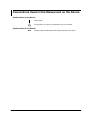
Checking the Contents of the Package
Unpack the box and check the contents before using the device. If the contents are not
correct or missing or if there is physical damage, contact the dealer from which you
purchased them.
Bridge Head
Check that the model name given on the name plate match that on the order. When
contacting the dealer from which you purchased the device , please quote the device
No.
Made in Japan
Model
Model
Specifications
Description
701957
701958
Bridge resistance 120 Ω
Bridge resistance 350 Ω
Shunt CAL, enchanced shield
Shunt CAL, enchanced shield
No. (Device number)
When contacting the dealer from which you purchased the device, please quote this
number.
Standard Accessories
D-Sub cable
(for 701957, 701958)
B8023WP
Length: 5 m
2
Attaching Plate
B9947KR
2 Binding screws
(M4 × 5 mm)
This User’ Manual
IM 701957-01E
Conventions Used in this Manual and on the Device
Symbols Used on the Device
GND terminal
The operator must refer to an explanation in the User’s Manual.
Symbols Used in this Manual
Note
IM 701957-01E
Provides important information for the proper operation of the device.
3
Contents
Foreword ........................................................................................................................................ 1
Checking the Contents of the Package .......................................................................................... 2
Conventions Used in this Manual and on the Device ..................................................................... 3
4
1
2
Construction of the Device .................................................................................................. 5
Shunt Calibration ................................................................................................................ 7
3
4
Connecting the Strain Gauge .............................................................................................. 8
Fixing the Device in Place ................................................................................................. 10
5
6
Connecting to the Strain Instrument ................................................................................. 11
Calibrating Using a Shunt Resistor ................................................................................... 12
7
Specifications .................................................................................................................... 16
IM 701957-01E
1
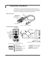
Construction of the Device
The bridge head is a converter for inputting the amount of change of the resistance of
the strain gauge to the amplifier. Six types of connection methods (single-gauge, singlegauge three-wire, adjacent-side two-gauge, opposed-side two-gauge, opposed-side twogauge three-wire, and four-gauge) are supported by setting the switch.
Names of the Parts
Cable
B8023WP
Strain gauge
connection terminal
Shunt resistant
connection terminal
Switch
Connector
GND terminal
Connect to a measuring instrument.
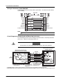
Terminals and Circuit Diagram
GND terminal
Sense+
Bridge+
BRIDGE HEAD(120 )
(SHUNT CAL, ENHANCED SHIELD)
GAUGE SELECT
ON
SHUNT CAL
Strain gauge
connection
terminal
(Terminal
number)
4GAUGE
7 8 9
1
1GAUGE
7 8 9
STRAIN GAUGE
2
3
4
2GAUGE
5
7 8 9
6
9
1
SHUNT CAL
9
8
7
3
3
2
5
2
Input4
Input+
8
Input-
7
Sense+
5
Sense-
2
BridgeSense-
6
Input+
6
R
Shunt resistant
connection
terminal
BridgeR
(Switch number)
OFF
SW 1 2 3 4 5
SHUNT RESISTANCE
Suntcal+
2GAUGE
Suntcal-
Switch
Bridge+
1
R
1GAUGE
Suntcal+
Suntcal-
4GAUGE
4
3
Floating Common
1
D-Sub connector
GND terminal
Shell
Pin assignments of the connector (Bridge head side)
Pin
symbol Signal name
1
Floating common
5 4 3 2 1
2
Sense– (Sensing of the bridge voltage-)
3
Shuntcal–(Shunt signal–)
4
Shuntcal+(Shunt signal +)
5
Sense+ (Sensing of the bridge voltage+)
6
Bridge– (Bridge voltage –)
9 8
7 6
7
Input– (Measurement signal –)
8
Input+ (Measurement signal +)
9
Bridge+ (Bridge voltage +)
IM 701957-01E
The numbers inside are the terminal
numbers.
The numbers inside are the switch
numbers.
The numbers inside are the pin
numbers of the connector.
5
1 Construction of the Device
Wiring for Accessory Cable B8023WP
A wiring diagram for the accessory cable is given below. The connector shell connects
to the shielding.
B8023WP
6
1
6
1
9
5
9
5
9
6
Input+ 8
Input7
Sense+ 5
Sense2
Shuntcal+ 4
Shuntcal3
Floating Common 1
9
6
8
7
5
2
4
3
1
Bridge+
Bridge-
Twist
Twist
Twist
Twist
Shell
Bridge+
BridgeInput+
InputSense+
SenseShuntcal+
ShuntcalFloating Common
Shell
Shield
Note
Check the shape and pin assignment of the connector before connecting it to the accessory
cable.
Circuit Diagram for Bridge Head and Measuring Instrument
The circuit diagram below shows the bridge head connected to a measuring instrument
(the DL750). Isolate the strain gauge before use.
CAUTION
Do not connect the strain gauge terminal to any items with electric potential.
Measurement instrument
(example: DL750)
Bridge Head 701957/701958
(with shunt calibration support)
Bridge+ Bridge+
BridgeInput+
InputSense+
R
Shuntcal-
Shuntcal+
R
Input+
Input-
BridgeSense-
SenseShuntcal+
Shuntcal-
Case
Sense+
Sense-
B8023WP
R
GND
terminal
Shunt resistor
Sense+
Floating
Common
The floating common of the
module is grounded within
the bridge head. *1
9
6
8
7
5
2
4
3
1
Twist
Bridge+
BridgeInput+
Twist
InputSense+
Twist
SenseSuntcal+
Twist
Shell
The connector shell
is connected to the
case potential of the
bridge head. *2
SuntcalFloating Common
Shield
The shield is connected
to the bridge head case
and the measurement
instrument case. *2
9
6
8
7
5
2
4
3
1
Shell
+
-
Module
701271
STRAIN_DSUB
Bridge
Power
+
-
AD
Sense+
SenseShuntcal+
Shuntcal
ON/OFF
ShuntcalFloating
Common
All module
signals are
isolated.
The connector shell is connected
to the case potential of the
measurement instrument.*2 Case
*1 The GND (floating common) of the module is connected to the case potential inside the bridge head.
*2 The bridge head case, the cable shield, and the measurement instrument case are connected as measures against noise.
6
IM 701957-01E
2
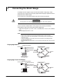
Shunt Calibration
This instrument supports shunt calibration. When executing shunt calibration, perform
balancing without applying a load to the strain gauge, then turn on shunt resistance. The
values from the shunt resistance are stored on the measuring instrument.
Balance
Shunt calibration
Strain
Strain
After execution
Gain is corrected.
Before execution
After execution
Before execution
Current measured
value*
P2:X
Strain input
Strain input
The zero point is corrected
when balancing is executed.
P2:Y
The strain value corresponding to
the shunt resistor is set to P2:Y of
the setup menu.
* Automatically obtained when shunt calibration is executed.
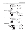
Shunt calibration is used to correct the gain of strain measurements by inserting a known
resistance (shunt calibration resistance (shunt resistance)) in parallel with the strain
gauge. With this instrument, the gain can be corrected on both the positive and negative
sides. Make sure to notice whether the corresponding strain values are positive or
negative.
When correcting the gain on the negative side (normal)
Shunt resistor insertion terminal: between 8 to 9
Set negative to the corresponding strain value.
Strain
gauge
Bridge+
0
12
Ω
In+
0
12
In-
Bridge
voltage
Ω
Shunt resistant
connection terminal
Shunt resistor
(Applied to the bridge head)
0
7 8 9
Shunt calibration relay
circuit (Built into the
strain module. Turns
ON/OFF automatically
when shunt calibration
is executed.)
Ω
12
Shunt resistor
Bridge-
When correcting the gain on the positive side
Shunt resistor insertion terminal: between 7 to 8
Set positive to the corresponding strain value.
Shunt resistor
(Applied to the bridge head)
Strain
gauge
Bridge+
0
12
Ω
Shunt resistant
connection terminal
Bridge
voltage
0
12
Ω
In+
In-
0
7 8 9
Shunt calibration relay
circuit (Built into the
strain module. Turns
ON/OFF automatically
when shunt calibration
is executed.)
Ω
12
Shunt resistor
Bridge-
For specific instructions on performing shunt calibration, refer to your measuring
instrument’s user’s manual. For information on shunt resistance and the corresponding
strain values, see page 13 in “Calculation of the Shunt Resistance.”
IM 701957-01E
7
3
Connecting the Strain Gauge
The bridge head can support six types of connection methods: single-gauge, singlegauge three-wire, adjacent-side two-gauge, opposed-side two-gauge, opposed-side twogauge three-wire, and four-gauge.
Do not connect the strain gauge terminal to any items with electric potential.
CAUTION
Do not connect the strain gauge terminal to any items with electric potential.
Use the lead wires included with the strain gauge or wires meeting the following
specifications to connect the strain gauge and the bridge head.
• Usable wire: single wire φ 0.14 to 1.5 mm2, or stranded wire 0.14 to 1.5 mm2 (AWG26
to 16)
• Normal length of bare wire : 6 mm
Note
•
•
•
•
•
Isolate the strain gauge before use.
Make the wires between the strain gauge and bridge head as short as possible.
Proper measurements may not be possible in an environment where electromagnetic
interference exists.
If you are shielding the strain gauge, connect the shield wire to the floating common
terminal of the bridge head.
For the handling of the strain gauge, see the instruction manual that came with the shield
gauge.
Single-gauge Method
Bridge head terminal
Strain gauge
1 Bridge+ (Sense+)
2
3
4
5
6
Strain gauge
Input- (Shuntcal-)
Bridge- (Sense-) Shunt
resistor
Input+
Shuntcal+ 8
3
2
Input-
Bridge+
Sense+
5
6
Input+
6
Input+
Shuntcal-
ON
OFF
1
9
7
1 2 3 4 5
4
Switch setting of
the bridge head
Bridge-
Shuntcal SenseON/OFF
Single-gauge Three-wire Method
Bridge head terminal
Strain gauge
1
Bridge+ (Sense+)
2
3
4
5
6
Strain gauge
Input- (Shuntcal-)
Bridge- (Sense-) Shunt
resistor
Input+
Shuntcal+8
2
Input-
5
7
1 2 3 4 5
Switch setting of
the bridge head
8
3
Bridge+
Sense+
Shuntcal-
ON
OFF
1
9
4
Bridge-
Shuntcal SenseON/OFF
IM 701957-01E
3 Connecting the Strain Gauge
Adjacent-Side Two-gauge Method
Bridge head terminal
Strain gauge
Bridge+ (Sense+)
1
2
3
4
5
6
Strain gauge
1
Input- (Shuntcal-)
Bridge- (Sense-)
Bridge+
Sense+
Input+ 3
Input+
5
6
Input-
ON
OFF
1 2 3 4 5
4
Switch setting of
the bridge head
Strain gauge
BridgeSense-
Opposed-Side Two-gauge Method
Bridge head terminal
Strain gauge
Strain gauge
1
Bridge+ (Sense+)
2
3
4
5
6
Bridge+
Sense+
1
Input- (Shuntcal-)
Bridge- (Sense-)
3
Input+
2
Input+
5
6
Input-
ON
OFF
1 2 3 4 5
4
Bridge- Strain gauge
Sense-
Switch setting of
the bridge head
Opposed-Side Two-gauge Three-wire Method
Bridge head terminal
Strain gauge
Strain gauge
1
Bridge+ (Sense+)
2
3
4
5
6
1
Input- (Shuntcal-)
Bridge- (Sense-)
3
Input+
2
Bridge+
Sense+
Input+
5
6
Input-
ON
OFF
1 2 3 4 5
4
Bridge- Strain gauge
Sense-
Switch setting of
the bridge head
Four-gauge Method
Bridge head terminal
1
2
3
4
5
6
Strain gauge
Bridge+ (Sense+) Strain gauge
Bridge+
Sense+ Strain gauge
1
Input- (Shuntcal-)
Bridge- (Sense-)
Input+
Input+ 3
6
Input-
ON
OFF
1 2 3 4 5
Switch setting of
the bridge head
IM 701957-01E
4
Strain gauge
Bridge- Strain gauge
Sense-
9
4
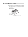
Fixing the Device in Place
If necessary, you can use the accessory attaching plate, B9947KR, to fix the bridge head
to the panel.
1.
Align the small holes on the bottom side of the bridge head to the small projections
of the attaching plate.
2.
Screw the bridge head and the attaching plate together using the accessory
binding screws (M4 × 5 mm).
Bridge head
Attaching
plate
B9947KR
Projections
Binding screws (M4 x 5mm)
10
IM 701957-01E
5
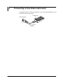
Connecting to the Strain Instrument
The bridge head uses a D-Sub 9-pin connector. The accessory cable, B8023WP, is used
to connect to the strain instrument.
Bridge head
Strain instrument
Accessory cable
B8023WP
IM 701957-01E
11
6
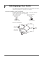
Calibrating Using a Shunt Resistor
Shunt calibration can be performed by combining with the YOKOGAWA's strain module
(Model 701271 (STRAIN_DSUB) that supports shunt calibration.
Connection procedures for the shunt resistor
The following two connection methods are available. In normal cases, connect the
resistor in correcting the gain on the negative side.
When correcting the gain on
the negative side (normal)
When correcting the gain on
the positive side
Shunt resistor
Shunt resistor
7 8 9
7 8 9
Shunt resistant
connection terminal
Shunt resistant
connection terminal
Example for single-gauge method
Sense+ Bridge+
Strain
gauge
1
9
R
Shunt resistor
(negative side)
5
Input4
Shuntcal+
Shuntcal-
12
6
Input+
Bridge
voltage
R
Shuntcal+
7
2
R
Shunt resistor
(positive side)
3
Shuntcal-
8
BridgeSense-
Shuntcal
ON/OFF
IM 701957-01E
6 Calibrating Using a Shunt Resistor
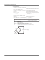
Calculation of the Shunt Resistance
Shunt calibration and shunt resistance
To execute shunt calibration, the shunt resistance (Rs) and the expected strain (ε) need
to be calculated in advance. Use ε as given in the equation below (normally a negative
value). With the DL750 (model 7071271), enter the value into “P2-Y” under the shunt
calibration execution menu. However, when using the general method given for shunt
calibration (the easy method), an error of 1 to 2% can be introduced as the strain value
(ε) increases. Therefore, calculate using the detailed method whenever possible. Also,
you must select a setting range value that will not result in an overrange.
Equation for Rs and e When Executing Shunt Calibration
• General Equation
∆R/R = K×ε
(1): Basic Equation of Strain
∆R = R–R//Rs
(2): Equation of the change in resistance when the shunt
resistance is ON
Note:In this manual, the parallel equation of resistors are expressed as follows:
1
R//Rs=
= R×Rs
1
1
R+Rs
R + Rs
If ∆R is cancelled out from (1) and (2),
Rs=R×(1-K×ε)/(K×ε)
ε:
K:
R:
∆R:
Rs:
IM 701957-01E
(Equation A): General equation used to calculate the
shunt resistance (includes error)
Strain (strain you wish to generate when the shunt resistance is turned ON)
Gauge factor
Bridge resistance
Resistance change
Shunt resistance (shunt resistance you wish to derive)
13
6 Calibrating Using a Shunt Resistor
• Detailed Equation
V0=E×(R1×R3–R2×R4)/{(R1+R2)×(R3+R4)}
(1): Basic Equation of Wheatstone Bridge
When shunt calibration is ON,
V0=E×(R1×R3–R'×R4)/{(R1+R')×(R3+R4)}
(2): Equation when turned ON
(3): Equation of combined resistance R'
(4): Since R1 to R4 are equal, we represent
them as R
R'=R2//Rs
R1=R2=R3=R4=R
Also, from the basic equation of strain,
V0/E=K×ε/4
(5): Basic equation of strain
If V0/E and R1 to R4 are cancelled out from (2), (3), (4), and (5),
Rs=R×(1–K×ε/2)/(K×ε)
E:
V0:
R1 to R4:
Rs:
R':
Bridge voltage
Bridge output voltage
Bridge resistance (except, R1=R2=R3=R4)
Shunt resistance (shunt resistance you wish to derive)
Combined resistance when the relay is turned ON (R'=R//Rs)
R1
R4
V0
R2
(Equation B): Detailed equation used to calculate
the shunt resistance (no error)
E (Bridge power supply)
R3
Rs
14
IM 701957-01E
6 Calibrating Using a Shunt Resistor
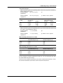
Calculation Example
• When Determining the Corresponding Shunt Resistance (Rs) from the Strain (ε)
Given a gauge factor (K) of 2,
Detailed equation
Rs = R×(1–ε)/(2×ε)
(6)
(equation B)
General equation
(equation A)
Rs = R×(1–2×ε)/(2×ε)
(7): Error of 1 to 2% present
Desired Strain
ε (µSTR)
Derived by the Detailed Equation (6)
Rs Value (Ω)
R=120 Ω
R=350 Ω
Rs value (Ω) Derived by the
General Equation (7)
R=120 Ω
R=350 Ω
1,000
2,000
5,000
10,000
59,940
29,940
11,940
5,940
59,880
29,880
11,880
5,880
174,825
87,325
34,825
17,325
174,650
87,150
34,650
17,150
• When Determining the Corresponding Strain (e) from the Shunt Resistance (Rs)
If we derive e from equation (6) and (7),
Detailed equation
ε = 1/(1+2×Rs/R)
(8)
(equation B)
General equation
(equation A)
ε = 1/{2×(1+Rs/R)}
(9): Error of 1 to 2% present
When the Bridge Resistance R is 120 W
RS Value (Ω)
Strain ε (µSTR) Derived by
the Detailed Equation (8)
Strain ε (µSTR) Derived by
the General Equation (9)
60,000
30,000
12,000
6,000
999
1,996
4,975
9,901
998
1,992
4,950
9,804
When the Bridge Resistance R is 350 W
RS Value (W)
Strain ε (µSTR) Derived by
the Detailed Equation (8)
Strain ε (µSTR) Derived by
the General Equation (9)
180,000
90,000
36,000
18,000
971
1,941
4,838
9,629
970
1,937
4,814
9,537
For the procedures related to performing the shunt CAL, see the manual that came with
the strain module that you are using.
Shunt CAL may not operate correctly on some strain measurement instruments. Check
this with the manual that came with the strain measurement instrument.
IM 701957-01E
15
7
Specifications
Bridge resistance
Model 701957: 120 Ω
Model 701958: 350 Ω
Applicable gauge methods
Single-gauge
Single-gauge three-wire
Adjacent-side two-gauge
Opposed-side two-gauge
Opposed-side two-gauge three-wire
Four-gauge
Operating conditions
Temperature:
Humidity:
5 to 40°C
20 to 85% RH
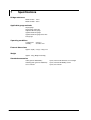
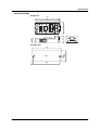
External dimensions
Approx. 50(W) × 101(H) × 29(D) mm
Weight
Approx. 100 g (Bridge head only)
Standard accessories
Cable (part no.: B8023WP):
Attaching plate (part no.: B9947KR):
User’s manual:
16
1 piece, with D-Sub connector, 5 m in length
1 piece, with two M4 binding screws
1 piece, this manual
IM 701957-01E
3.5
46
5
IM 701957-01E
29
18
ON
1GAUGE
1
2
4
50
2GAUGE
3
5
7 8 9
STRAIN GAUGE
6
4GAUGE
7 8 9
SHUNT CAL
4GAUGE
(SHUNT CAL, ENHANCED SHIELD)
GAUGE SELECT
OFF
SW 1 2 3 4 5
SHUNT RESISTANCE
7 8 9
SHUNT CAL
2GAUGE
1GAUGE
BRIDGE HEAD(120 )
7 Specifications
External drawings
Bridge head
101
96
Attaching plate
119
108
17
YOKOGAWA ELECTRIC CORPORATION
Headquarters
2-9-32, Nakacho, Musashino-shi, Tokyo, 180-8750 JAPAN
Sales Headquarters
2-9-32, Nakacho, Musashino-shi, Tokyo, 180-8750 JAPAN
Phone : 81-422-52-6194
Branch Sales Offices
Nagoya, Osaka, Hiroshima, Fukuoka, Sapporo, Sendai, Ichihara, Toyoda,
Kanazawa, Takamatsu, Okayama, and Kitakyusyu.
Overseas Representative Offices / Service Centers
Beijing, Shanghai (The People's Republic of China), Jakarta (Indonesia),
Kuala Lumpur (Malaysia), Bangkok (Thailand)
YOKOGAWA CORPORATION OF AMERICA
Headquarters
2 Dart Road, Newnan, Ga. 30265-1094, U.S.A.
Phone : 1-770-253-7000
Fax : 1-770-251-0029
Branch Sales Offices / Detroit, Chicago, Los Angeles, New Jersey, Oklahoma,
Texas, San Jose, Stafford
YOKOGAWA EUROPE B. V.
Headquarters
Databankweg 20 Amersfoort 3821 AL, THE NETHERLANDS
Phone : 31-334-64-1611 Fax : 31-334-64-1610
Branch Sales Offices / Wien (Austria), Zaventem (Belgium), Ratingen
(Germany), Madrid (Spain), Runcorn (United Kingdom), Milano (Italy),
Velizy Villacoublay (France), Johannesburg (Republic of South Africa),
Budapest (Hungary), Stockholm (Sweden)
YOKOGAWA AMERICA DO SUL S.A.
Praca Acapulco, 31 - Santo Amaro. Sao Paulo/SP - BRAZIL
Phone : 55-11-5681-2400 Fax : 55-11-5681-1274
YOKOGAWA ELECTRIC ASIA PTE. LTD.
Head Office
5 Bedok South Road, 469270 SINGAPORE
Phone : 65-6241-9933 Fax : 65-6241-2606
YOKOGAWA ELECTRIC KOREA CO., LTD.
Head Office
420-5, Chongchun - 2dong, Pupyong - ku Inchon, 403-032 KOREA
Phone : 82-32-510-3107 Fax : 82-32-529-6304
YOKOGAWA AUSTRALIA PTY. LTD.
Head Office (Sydney)
Centrecourt D1, 25-27 Paul Street North, North Ryde,
N.S.W.2113, AUSTRALIA
Phone : 61-2-9805-0699 Fax : 61-2-9888-1844
YOKOGAWA BLUE STAR LTD.
Head Office
40 / 4 Lavelle Road, Bangalore 560 001, INDIA
Phone : 91-80-2271513 Fax : 91-80-2274270
Sep. '02
<Recycled Paper Used>
Printed in Japan