1
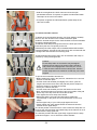
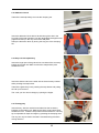
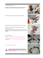
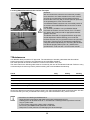
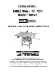
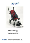
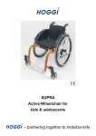
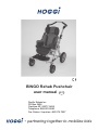
BINGO Rehab Pushchair
user manual
GB/US
Pacific Rehab Inc
PO Box 5406
Carefree AZ, 85377-5406
Telephone: 888.222.9040
Fax Orders / Inquiries: 480.575.7907
- partnering together to mobilize kids
User Manual for BINGO Rehab Pushchair
Contents
Page
1
Common Information
1.1 Preface ___________________________________________________________________ 2
1.2 Application _________________________________________________________________ 2
1.3 Declaration of conformity______________________________________________________ 2
1.4 Terms of warranty ___________________________________________________________ 2
1.5 Servicing and repairs_________________________________________________________ 2
2
Safety Instructions ______________________________________________________________ 3
2.1 Meaning of symbols _________________________________________________________ 3
2.2 Common safety instructions ___________________________________________________ 3
3
Delivery and Preparing for Use ____________________________________________________ 6
4
Adjusting and Adaptation Possibilities ____________________________________________ 10
4.1 Wheel lock ________________________________________________________________ 10
4.2 Height adjustment of push handle ______________________________________________ 10
4.3 Seat depth and seat width ____________________________________________________ 11
4.4 Hip pads _________________________________________________________________ 11
4.5 Back height _______________________________________________________________ 11
4.6 Recline __________________________________________________________________ 12
4.7 Knee Angle _______________________________________________________________ 12
4.8 Lower leg length ___________________________________________________________ 12
4.9. Footrest angle adjustment ____________________________________________________ 12
4.10 Footrest lock (optional) ______________________________________________________ 13
4.11 Detaching and Attaching the seat unit ___________________________________________ 13
4.12 Use of seat unit against driving direction_________________________________________ 13
4.13 Tilt in space _______________________________________________________________ 14
4.14 Detaching wheels with quickrelease ____________________________________________ 15
4.15 Suspension _______________________________________________________________ 15
4.16 Pneumatic tyres____________________________________________________________ 15
5
Accessories ___________________________________________________________________ 16
5.1 Swivel Lock _______________________________________________________________ 16
5.2 Storage Bag ______________________________________________________________ 16
5.3 Headrest Pads_____________________________________________________________ 17
5.4 Thorax Pads ______________________________________________________________ 18
5.5 Lap Belt __________________________________________________________________ 19
5.6 Five-point Harness _________________________________________________________ 20
5.7 Foot Straps _______________________________________________________________ 21
5.8 Frame Padding ____________________________________________________________ 22
5.9 Groin Strap _______________________________________________________________ 22
5.10 Fixation Jacket ____________________________________________________________ 23
5.11 Chest-Shoulder Harness _____________________________________________________ 24
5.12 Abduction Block____________________________________________________________ 25
5.13 Grap Rail with upholstery ____________________________________________________ 25
5.14 Therapy Tray ______________________________________________________________ 25
5.15 Winter Warmer ____________________________________________________________ 26
5.16 Rain Cape ________________________________________________________________ 26
5.17 Canopy __________________________________________________________________ 27
5.18 Attendant brake ____________________________________________________________ 27
5.19 Ankle huger _______________________________________________________________ 28
6
Transportation _________________________________________________________________ 28
6.1 In the Trunk of a Car ________________________________________________________ 28
6.2 Using BINGO Rehab Pushchair for Bus Transport _________________________________ 29
7
Maintenance __________________________________________________________________ 29
8
Technical Data _________________________________________________________________ 30
1
1 Common Information
1.1 Preface
Thank you for selecting the BINGO Rehab Puschchair. We have designed this high-quality product to make
your life safer and easier, and we’ve included this manual to help you use and care for it.
Please read the following instructions to make sure you use this product as recommended. If
you have any further questions, or if you have any problems, please contact your healthcare provider.
We hope that BINGO meets your expectations.
The design, as described in these Instructions for use, are subject to technical alterations without notice.
1.2 Application
Rehab pushchairs, paediatric postural positioning systems or strollers are appropriate for individuals
requiring mobility assistance.
Assistance may be required due to:
• atypical muscle tone;
• loss of limbs;
• joint instability;
• joint contractures;
• joint defects;
• general weakness.
1.3 Declaration of Conformity
HOGGI® GmbH as manufacturer with sole responsibility declares that the BINGO Rehab Pushchair
conforms to the requirements of the 93/42/EEC Guidelines.
1.4 Terms of Warranty
Warranty applies only when the product is used according to the specified conditions and for the
intended purposes, following all manufacturer’s recommendations.
1.5 Service and Repairs
Service and repairs on the BINGO should only be carried out by authorized HOGGI dealers. Should any
problems arise, please contact the dealer who supplied your BINGO. Authorized dealers only fit original
HOGGI spare parts.
For repair and service, the following tools are required:
Allen wrench, sizes 3 mm, 4 mm, 5 mm and 6 mm;
wrench, sizes 10 mm, 13 mm, 19 mm.
US Distributor:
Pacific Rehab Inc
PO Box 5406
Carefree AZ, 85377-5406
Telephone: 888.222.9040
Fax Orders / Inquiries: 480.575.7907
2
2
Safety instructions
2.1
Meaning of symbols
Caution!
Warning of possible danger of accident and injury. Warning of possible technical damage.
Information!
about use of product.
Information!
for service-personnel.
Attention!
Read manual before use!
2.2
Common safety instructions
Read manual completely before use!
Familiarize yourself with handling and functions of the product before use and practice the
handling.
You are responsible for the safety of your child. The safety of your child could be
affected if you do not follow the instructions of this manual. Nevertheless not all possible
circumstances and unpredictable situations can be covered by this manual. Reason, care
and circumspection are not features of the product, they are required of persons, who use
the product. The person, who is using the product and its accessories should understand
all instructions and should explain them to every person using the product and its
accessories.
If instructions are not clear and further explanations become necessary, or if you have
further questions please contact your HOGGI dealer.
Strap your child at any time in the pushchair.
HOGGI points out, that any use beside the typical use can be dangerous. The pushchair
is not suitable for jogging, running, skating or similar activities. Swivelling front wheels tend
to wobble at higher speed, which can cause a sudden stop and tip over of the pushchair.
Use the pushchair only at regular walking speed.
Under no circumstances leave the handle bar while pushing and never push the chair
away.
The pushchair should only be used on solid level ground.
Use your pushchair as intended by the manufacturer. For instance, do not drive into
obstacles (including steps, curbs) without braking.
To clear obstacles such as steps and curbs, tilt the pushchair onto the rear wheels (pull it
backwards to go up; to descend, slowly lower it forward).
Do not go up or down stairs without the assistance of another person. If devices such
as ramps or elevators are available, please use them. If they are not available, then the
pushchair should be carried over the obstacle by two persons.
3
Pay particular attention when on slopes and inclines to prevent
- the child from falling out of the pushchair;
- the pushchair from tipping over;
- the pushchair from rolling away.
If you have to park on a slope, face the pushchair uphill with the brakes engaged and
ensure that the seat is in the upright position. There is a risk that the pushchair might tip
over backwards if the seat is the reclined position.
Before leaving the pushchair and before getting into and out of it, always lock the wheel
locks.
Do not stand on the footplate when getting into or out of the pushchair
Only lift the pushchair by parts that are solidly attached:
- front frame tube above the front wheels;
- rear axle;
- push handles / pushbar.
When your child reaches for objects in front, to the side or behind the pushchair, be sure
that he/she does not lean out of the pushchair too far since the shift in the center of gravity
might cause the pushchair to tilt or tip over.
The handling of the pushchair is strongly influenced by tyre pressure. Correctly inflate tyres
considerably improve its maneuverability. The air pressure should be at least 2 bar
(200 kPa resp. 29 PSI).
Please be aware that with certain footrest settings the footrest can collide with the caster
wheels.
Please keep packaging material away from children. Plastic packaging presents the
danger of suffocation.
Never leave your child unattended in the pushchair even when they are strapped in and
the brakes engaged.
Before using the pushchair, both folding guards and the seat must be firmly locked in
place.
Static stability is at 18° inclination.
Attaching heavy bags or other weight to the push handles can adversely affect stability.
The maximum weight that can be carried in the storage bags is 5 kg.
Trays must not be loaded with objects heavier than 5 kg.
The puschair is only intended to carry one child at a time.
4
The maximum load for the BINGO street frame is 50 kg.
The maximum load for the BINGO seat unit is 35 kg.
Accessories and add-ons reduce the maximum load proportionately.
Attention!
We recommend that, wherever and whenever possible, users transfer to the seats installed
in the motor vehicle and use the corresponding vehicle restraint systems, because this is
the only way to ensure optimum protection of the passengers in case of an accident.
Your BINGO Rehab Pushchair was successfully tested in accordance with ANSI/RESNA
WC/19 and ISO 7176/19 (Crash Test).
It is, however, possible to use your BINGO Rehab Pushchair as a seat in a motor vehicle, if
our “Tie down Kit” (article 3201-7300) as well as appropriate restraint systems are used.
This Rehab Pushchair is equipped with back angle and seat tilt adjustment. Before starting
you must tilt the backrest until the lock pin (A) locks into the hole (B) in the back plate. Tight
the lever (C) well after this adjustment. Using the seat tilt adjustment you must bring the
backrest into almost upright position (max. 20°). Observe the specifications under 4.6 and
4.13 in this user manual.
Caution!
Excess strap ends on accessories may be trapped between the two parts of the seat
mounting interface and prevent a full engagement of the lock pin. In such a case the seat
could fall off the mobility base. Shorten excess strap ends on accessories so that they can
not be trapped.
Check by pulling the seat sharply forward that the seat unit is properly engaged. Check
that the lock pin is completely engaged. Push in completely, if necessary.
Whenever you change any settings on the BINGO rehab pushchair, make sure that you
firmly tighten any screws that have been loosened.
5
3 Delivery and Preparing for Use
The original package contains the following components:
• outdoor mobility base, folded;
• seating unit, folded;
• back insert
• seat, back, hip and lateral padding;
• instructions for use and list of tools required;
• accessories as ordered.
Carefully remove the transport safety items and packaging material.
To unfold the Pushchair please proceed as follows:
• Lift the pushchair using the black handle grip on the pushbar and
unfold it until you can set it on its wheels.
• Press the pushbar backward until the folding guards engage.
• Check both folding guards and engage them if necessary.
• Push the rear wheels (with perforated brake disk!) on the rear axle
stub until the quick release engages. Ensure that the wheels are
safely fixed on the axle stub by pulling in the opposite direction.
If you have a pushchair with rigid front wheels proceed in the same
way.
• Release the clamping lever on the backrest and turn the backrest
to about 90° against the seat surface.
6
• After setting the backrest to the desired position clamp it firmly
with the clamping lever. By pulling the handle of the clamping lever
backwards you can rotate it freely and find a optimal position to
operate it.
• To overcome the child protection pull the trigger outside first.
• Pull then the trigger upward until the locking device opens the tilt
mechanism and swing the seat unit to the desired position.
• Disengage the trigger and swing the seat unit until the locking
device locks with a hearable click.
• Swing the knee angle assembly with the footrest to the desired
position and fix it with the clamping lever
• Put the back insert into the back base of the backrest and adjust to
the desired height by tightening the clamping bolts. If your BINGO
is delivered with a canopy accessory , put the adapter fittings
on the tubes with the back insert in place. Refer to chapter 5
accessories 5.17 canopy.
7
• The Allen wrench (size 4 mm) for this and for most other
adjustments you can find mounted in the joint slider of the backrest
• In addition to the clamping bolts, the back insert is fixed and
secured by two carriage bolts with knurled nuts, which also limit
the maximum back height.
• It is recommended to adjust the seat unit to the desired settings
before you put on the upholstery parts. See therefore chapter 4
„Adjusting and Adaptation possibilities“
• Put the seat upholstery on the seat so that the corresponding hook
& loop straps on seat and upholstery are connected. The rear part
of the upholstery should line up with the rear seat edge.
• Put the hip upholsteries on the hip brackets and connect the
corresponding hook & loop straps
8
• Put the lateral upholsteries on the lateral brackets and connect the
corresponding hook & loop straps.
• Pull the back upholstery with the cap onto the back insert.
• Connect the corresponding hook & loop straps to the back
insert so that the shoulder belt slots line up with the upper edge
(shoulder) of the back upholstery.
• Push the lower end of the back upholstery through the gap
between back and seat and attach the back upholstery to the rear
seat edge by the corresponding hook & loop straps.
9
To fold the BINGO rehab pushchair proceed as follows:
• Stand behind the push bar. Pull both folding guards and push the
push bar forward.
• After disengaging the folding guards hold the upper part of the
push handle and fold it forward until it touches the front frame and
the pushchair is lying on the floor
4 Adjusting and Adaptation Possibilities
4.1 Wheel lock
To put the wheel lock on push the wheel lock lever downwards and
roll the pushchair slightly back or forward, so that the lock pins can
engage in the brake disc. Never use force! This could damage the
quickreleases and the wheels could fall off and cause injuries.
To disengage the wheel lock pull the wheel lock lever upwards
with your toe.
4.2 Height adjustment of the push handle
The ratchet joints allow adjustment of the push handle to a
convenient height. To operate the ratchet joints, push the buttons on
the outside of the push handle.
10
4.3 Seat depth and seat width
After loosening the knurled nuts underneath the seat you can adjust:
• The seat depth by moving the knee angle assembly in or out .
The minimum seat depth of 16 / 21 cm (6 - 8 inches) that you
achieve is accomplished by taking out the four foam pads (access
from underneath) in the front part of the seat upholstery.
• The seat width by moving the hip pads in or out
Whenever you change any settings on the BINGO rehab
pushchair, make sure that you firmly tighten any screws
that have been loosened.
4.4 Hip pads
After loosening the button head socket screws the hip pads can be
adjusted forward or backward.
Whenever you change any settings on the BINGO rehab
pushchair, make sure that you firmly tighten any screws
that have been loosened.
4.5 Back height
Loosen the clamping screws at the upper end of the back base and
the knurled nuts of the two carriage bolts and adjust to the desired
back height. Tighten the bolts firmly.
From a back height of approximately 55 cm for seat size 1 and 66 cm
for seat size 2 the back frame has to be placed to the lower position
on the back metal sheet.
Whenever you change any settings on the BINGO rehab
pushchair, make sure that you firmly tighten any screws
that have been loosened.
11
4.6 Recline
Stand behind the seat first and put the wheel lock on. Secure the
back with one hand before you operate the clamping lever with the
other hand.
Adjust the back to the desired position and tighten the clamping lever
firmly again.
4.7 Knee angle
Put the wheel lock on and stand in front of the seat. Secure footrest
and knee angle assembly with one hand before you loosen the
clamping lever with the other hand. Swing the footrest to the desired
position and tighten the clamping lever firmly again.
4.8 Lower leg length
Put the wheel lock on and stand in front of the seat. Secure the
footrest with one hand before you loosen the clamping screws with
the other hand. Slide the footrest to the desired position and tighten
the clamping screws firmly again.
4.9 Footrest angle adjustment
After loosening the bolts on the left and the right sides of the
footrest, the footrest angle can be adjusted approximately up to 10°
up or down (dorsal, plantar).
Tighten bolts firmly again.
12
4.10 Footrest lock (optional)
By pulling the release strap the footrest lock is disengaged and the
footrest can be folded for better storage. If you swing the footrest
down again, it will lock automatically.
4.11 Detaching and attaching the seat unit
For easier transport handling you can dismantle your BINGO in two
parts by detaching the seat unit easily from the streetframe. This is
also of value, if you want to use the BINGO seat unit on an indoor
mobility base.
Before you detach or attach the seat unit always secure the
pushchair by putting on the brake.
Detaching
• Stand beside the seat unit.
• Hold the seat with one hand on the front seat edge.
• Push the secondary lock pin (arrow) as shown with the index finger
of the other hand and pull the lock pin underneath the seat with
thumb and middle finger and slide the seat unit slightly forward.
• Hold now the seat unit on back and front seat edge and lift the
seat unit from the trapezium adapter.
Attaching
• Hold the seat unit on back and front seat edge.
• Stand with the seat unit in your hands beside the mobility base.
• Put the seat unit from above and slightly forward from the end
position onto the base adapter
• Slide the seat unit backwards until you can hear the lock pin click
in place.
• Check by pulling the seat sharply forward that the seat unit is
properly engaged.
• Check that the lock pin is completely engaged. Push in completely,
if necessary.
Caution!
Excess strap ends on accessories may be trapped
between the two parts of the seat mounting interface
and prevent a full engagement of the lock pin. In such
a case the seat could fall off the mobility base. Shorten
excess strap ends on accessories so that they can not be
trapped. Check by pulling the seat sharply forward that
the seat unit is properly engaged. Check that the lock pin
is completely engaged. Push in completely, if necessary.
4.12 Use of the seat unit in a reverse riding direction
The seat unit can also be used in a reverse riding direction.
The pushchair can still be folded in this configuration.
13
Before use in the reverse riding direction the base adapter must be
rotated 180°.
Remove all four bolts and rotate the base adapter.
Tighten the bolts firmly again.
4.13 Tilt in space
The BINGO seat unit can be tilted up to 45° in driving direction and
40° against driving direction in steps of 8,5° degrees.
• Put on the wheel lock and stand beside the pushchair
• Tighten the clamping lever of the back rest adjustment firmly.
• Secure the seat unit with one hand holding onto the back rest.
• To avoid high resistance for the travel of the trigger release the
tilting mechanism by balancing the seat.
• To overcome the child protection pull the trigger outside first.
• Pull then the trigger upward until the locking device opens the tilt
mechanism and swing the seat unit to the desired position.
• Disengage the trigger and swing the seat unit until the locking
device locks with a hearable click.
Caution!
Check by pulling the seat sharply forward that
the locking device is properly engaged.
If so, the indicator hole (4) is complete covered
by the lever housing.
14
4.14 Detaching wheels with quickrelease
In order to achieve a most compact folding package the rear wheels
of all models and the front wheels of the models with rigid front
wheels are detachable by quick release hubs.
To detach press the quick release spring towards the middle of the
wheel and pull the wheel from the axle.
To attach the wheel push it onto the axle until the quickrelease snaps
in automatically.
Ensure that the wheel is securely held onto the axle by pulling the
wheel without operating the quickrelease.
Ensure, that rear wheels (with perforated brake disc) get attached to
rear axle!
4.15 Suspension
The BINGO puschair is equipped with an adjustable suspension.
By turning the set screw in, the suspension gets harder, by turning
out softer.
Make sure that the suspension is adjusted equally on both sides.
The scale in the window of the spring housing offers an orientation.
4.16 Pneumatic tyres
All wheels are equipped with pneumatic tyres.
Maintain proper pressure at all times
Notice the air pressure indicated on the tyre.
15
5 Accessories
All accessories not installed by the manufacturer must be installed by trained technicians.
The following notes on installation are for your information but should be performed by trained technicians.
Straps on accessories are usually extra long to accommodate every option.
Excess strap ends on accessories may be trapped between the two parts of the seat mounting
interface and prevent a full engagement of the lock pin. In such a case the seat could fall off the
mobility base. Shorten excess strap ends on accessories so that they can not be trapped.
To prevent strap ends from fraying the cut ends can be melted together with a flame.
(eg. cigarette lighter)
5.1 Swivel lock
The swivel lock is mounted by the manufacturer or an authorized
dealer.
To lock the swivel lock turn the lock pin by 90° and let it engage in
the designated hole in the castor fork.
To open the swivel lock pull the lock pin, turn it by 90° so that it stays
in the disengaged position.
After loosening the clamping screw the track can be adjusted with
engaged swivel lock.
5.2 Storage bag
The BINGO rehab pushchair can be equipped with a spacious
storage bag, which folds with the pushchair.
The maximum weight that can be carried in the storage
bags is 5 kg (11 lb).
The storage bag is attached with clips to the cross member of the
front frame and with snap fasteners to the rear frame.
16
If the storage bag gets overloaded the snap fasteners will open but
can be put together again easily.
If the seat unit is mounted against driving direction, the storage bag
also is mounted in reverse direction.
5.3 Headrest pads
The headrest pads are mounted with carriage bolts and knurled nuts
on the back insert.
For an easy mounting and for adjustments open the zipper of the
upholstery cap on the rear of the back and turn the rear head
upholstery back.
17
For a rough adjustment of the headrest width the self adhesive foam
pads are glued to the left and/or the right of the headrest brackets.
The cover is put on.
After loosening the knurled nuts the headrest pads can be moved in
or out for a fine width adjustment.
The height adjustment is realized by adjustment of the back insert.
5.4 Trunk pads
The trunk pads are mounted to the back with back upholstery
removed.
The set of holes in the back base and the back insert must be in line.
Eventually the height of the backrest has to be adjusted accordingly.
The height adjustment is made through the holes chosen.
After loosening the wing nut the trunk pad width can be adjusted by
swinging the crank from horizontal to vertical.
18
After reaching the desired position and tightening the wing nuts the
back upholstery is pushed underneath the trunk pads.
The angle of the trunk pad is fixed by tightening the clamping screw
underneath the trunk pad cover.
5.5 Lap belt
On each end of the lap belt you can find pre mounted triglides, which
are passed by the belt only once.
The length of the free belt ends determine the length of the complete
lap belt.
Pass the free belt ends through the designated slots in the lower part
of the back base.
Then thread the belt ends once again through the triglides.
Open the lap belt by pushing the red key on the buckle.
The lap belt can be adjusted by pulling the belt end next to the
buckle.
19
5.6 Five point harness
The five point harness should be installed by authorized dealers or
trained technicians.
Take the seat upholstery off first. Loosen all the carriage bolts of the
hip pads. Pull out the seat plate completely to get easy access to the
set of rectangular slots in the seat plate underneath the hook strap.
Choose one of them according to the desired seat depth and slot
it with a cutter. The position should be close to the body but not
underneath the bottom. Thread the strap from above through the
slot and between seatplate and seat base to the rear edge of the
seat plate. Place the thickned end of the strap right to this edge so
that the strap is firmly secured after tightening the bolts. Put the
seat plate and the hip pads to the desired position and tighten the
carriage bolts.
Put the seat upholstery back again and thread the other end of the
strap through the slot in the seat upholstery.
To attach the strap to the buckle proceed as described in 5.5 lap
belt.
Lead the shoulder straps together with the pad straps through the
designated slots in the back insert
Fix the shoulder straps to the slots in the back base as described in
5.5 lap belt
Tie the pad straps together.
The shoulder straps should be adjusted in a way that the housing of
the length adjusters rest on the shoulder padding.
20
Mount the lap strap ends of the five point harness as decribed in 5.5.
lap belt and preadjust them roughly.
To take the five point harnesss off proceed as follows:
• Press the red key on the buckle
• Press the keys of the length adjusters and pull the strap out so that
approx 5 cm (2 inches) of the strap end remains.
• Create wide loops which allow for the arms of your child to move
out of the harness easily.
• Lift your child out of the seat
To put the five point harness on proceed as follows:
• Place your child into the seat
• Put the elbow of your child through one of the shoulder strap loops
first and then the forearm and hand.
• Proceed with the other arm the same way.
• Put the buckle members one after each other into the buckle.
• Tighten shoulder and lap straps by pulling the strap ends coming
out of the length adjuster.
5.7 Foot straps
Thread the foot straps crosswise through the D-rings over the shoe/
foot of your child. The heel should be placed against the heel plate of
the footrest. Place the buckle always outward.
Pull the free strap end to tighten the foot straps.
Press the key on the buckle to open the buckle.
21
5.8 Frame padding
Fit the frame padding around the pushbar and close the hook & loop
strap.
Turn the hook & loop closure down and pull the frame padding down
over the folding guard and front frame screw connection.
Before folding the pushchair, lift the padding up until the folding
guard is free.
5.9 Groin strap
We recommend you to take the seat off the mobility base to mount
the groin strap.
Thread the tensioning straps for the thigh belts (the end with a loop)
through the slots on the right and left side in the lower end of the
back base.
Thread the free end through the loop and tighten the tensioning
strap. Now pull the free ends of the tensioning straps toward the seat
padding.
Then thread the tensioning straps into the buckles .
Position the groin strap with the quick-release buckles on the thigh
belts pointing downwards on the seat surface.
Caution!
Excess strap ends on accessories may be trapped
between the two parts of the seat mounting interface
and prevent a full engagement of the lock pin. In such
a case the seat could fall off the mobility base. Shorten
excess strap ends on accessories so that they can not be
trapped.
Thread the attachment straps of the groin strap between seat and
back padding, wrap them around the back of the seat edge and
attach with carriage bolts and knurled nuts of the hip pads.
The set of holes allow a length adjustment.
22
To put on the groin strap proceed as follows::
• Place your child into the pushchair on the groin strap.
• The part of the thigh belt with the buckle attached should lie on the
pelvic bone.
• Insert the male part of the quick-release buckles located on the
tensioning straps into the buckles on the thigh belts.
• Tighten the thigh belt by pulling the free end of the strap that
comes out of the buckle.
• To disengage the quickrelease buckle, press the key on the buckle.
5.10 Fixation jacket
To attach the fixation jacket straps, rivet (from inside to outside) the
six cam-lock buckles to the outside of the back plate.
Thread the shoulder straps of the fixation jacket through the shoulder
slots to the rear. The centre “axillary straps“ must be threaded at the
appropriate height between the back frame tube and back plate.
Thread the lower straps through the slots in the lower part of the
back base (see also 5.5 lap belt) to the rear.
Thread all straps through the open cam-lock buckles and clamp in
position by closing the hinged cam.
Caution!
Excess strap ends on accessories may be trapped
between the two parts of the seat mounting interface
and prevent a full engagement of the lock pin. In such
a case the seat could fall off the mobility base. Shorten
excess strap ends on accessories so that they can not be
trapped.
Opening the fixation jacket:
• Open the quick-release buckles on the shoulder part of the fixation
jacket
• Pull the zipper down and open the fixation jacket.
• Lift your child out of the seat.
Closing the fixation jacket:
• Place your child into the seat.
• Close the zipper.
23
• Hold the vest against the child’s chest and close the open
quickrelease buckles. If required, re-tighten the individual fixation
vest straps in the cam-lock buckles.
• If required, re-tighten the individual fixation jacket straps in the
cam-lock buckles.
5.11 Chest-shoulder harness
To attach the chest-shoulder harness, rivet (from inside to outside)
the four cam-lock buckles to the outside of the back plate.
Guide the shoulder straps for the chest-shoulder harness backwards
through the designated slots.
Thread the lower straps through the slots in the lower part of the
back base (see also 5.5 lap belt) to the rear.
Alternatively the lower straps can be threaded backwards between
seat and seatback through the roll loops which are mounted with the
carriage bolts and knurled nuts of the hip pads.
Thread all straps through the open cam-lock buckles and clamp in
position by closing the hinged cam.
Caution!
Excess strap ends on accessories may be trapped
between the two parts of the seat mounting interface
and prevent a full engagement of the lock pin. In such
a case the seat could fall off the mobility base. Shorten
excess strap ends on accessories so that they can not be
trapped.
To put the chest-shoulder harnesss on:
• Before seating the child in the puschair, release the four cam-lock
buckles on the back plate.
• Pull the chest and shoulder pad slightly to the front, open the
hinged cams at the lower end of the pad and pull the straps out.
• Place the straps on the sides of the seat.
• Place your child into the seat
• Pull the chest and shoulder pad over the head onto the chest.
• Next, thread the straps into the lower cam-lock buckles of the pad
all the way to the stop rivets and close the buckles.
• Then tighten the lower straps from behind.
• Make sure that the chest and shoulder pad is positioned
symmetrically on the pelvis and close the buckles on the lower
straps.
• Set the upper body of your child upright against the back.
• Finally, tighten the upper straps behind the seat and close the
buckles on the upper straps.
The fit and position of the harness is correct when the straps are not
touching the child and when the beaded edge of the harness is not in
contact with the strap guide slot.
The harness provides the best upper-body support when the strap
guide slot is approx. 2-3 cm above the child’s shoulder.
24
5.12 Abduction block
Take off the seat upholstery to mount the clamping set.
Insert the abduction block with its flat link through the slot in the
front part of the seat upholstery into the designated rectangular slots
(upper and lower!) in the very front of the seat plate.
Clamp the abduction block by turning the wing nut of the clamping
set.
5.13 Grap rail with upholstery
Insert the longer part of the grab rail into one side of the accessory
bracket of the seat unit. Make sure that the snap buttons point
towards the front.
Insert the shorter end into the other side of the accessory bracket
while pressing the snap button.
Take off the grab rail by both, pressing the snap button and pulling
the rail up to remove it.
The cover you can remove simply by opening the zipper.
5.14 Therapy tray
Insert the tray with the vertical round tubes into the accessory
brackets on the seating unit. Make sure that the snap buttons point
towards the front. Press the snap buttons at the same time. The tray
top is adjustable in depth and angle by operating the clamping lever.
The tray can only be used if the seat is mounted facing forward in
driving direction.
25
Trays must not be loaded with objects heavier than
5 kg (11 lb).
5.15 Winter warmer
Zippers allow the upper part of the winter warmer to be opened or
removed.
Place the winter warmer in the stroller and tie with the straps to the
lower back section and tie the upper straps to the frame of the back
insert.
Upper straps to the frame of the back insert.
Lower straps to the lower area of the back base.
5.16 Rain cape
With the zip-fastener open pull the rain cape over the child’s head,
then unfold the upper end over the backrest and the lower end
around the footrest.
26
5.17 Canopy with rain cover
First attach the canopy adapters to the back frame on the left and
right side. See also capter 3 “Delivery and preparing for use”.
Insert the male pins of the canopy into the canopy adapters.
Adjustable ratchet joints are used to set the angle of the canopy.
Spread the canopy and wrap over the backrest of the seat.
Canopy with Rain Cover:
Take the rain cover out of the bag attached to the wrap, unfold the
rain cover, pull it over the unfolded canopy and put it over the footrest
assembly.
5.18 attendant brake
The BINGO mobility base can be fitted with an attendant brake.
The brake mechanism can be operated with a single lever and a
cable switch
or with two independent brake lever.
The attendant brake is designed to be a brake and not
a wheel lock for parking. For parking the original wheel
lock remains in function.
27
Adjustments:
The attendant brake set is pre adjusted. Nevertheless, if adjustments
become necessary just after installation or after a period of use there
are following options:
After loosening the counter nut at the brake cable switch the pre
tension of both brake slings can be adjusted simultaneously by the
setscrew.
Tighten the counter nut firmly again.
At the exit of each brake housing a cranked set screw leads the
brake cable away from the tire of the rear wheel. After loosening the
counter nut the pre tension of the individual (left or right) brake can
be adjusted.
Tighten the counter nut firmly again and ensure that the crank of the
set screw shows towards the rear frame, away from the tire.
By adjusting the setscrews you can achieve an equable
braking of the rear wheels.
5.19 ankle huger
Ankle hugers allow a comfortable fixation of the foot joints. They are
fixed to anchors on the foot plate.
The heel should be placed against the heel plate of the footrest.
The belts are opened/closed and adjusted with velcro straps.
6 Transportation
6.1 In the Trunk of a Car
Basically you can store your rehab pushchair in the trunk of your car as
well with or without seat unit on as well as with or without wheels on.
The most compact size is achieved by removing the seat unit and
wheels by quick release mechanisms and placing them as shown in
the mobility base.
28
6.2 Using BINGO Rehab Pushchair for Bus Transport
B
C
A
Attention!
We recommend that, wherever and whenever possible,
users transfer to the seats installed in the motor vehicle
and use the corresponding vehicle restraint systems,
because this is the only way to ensure optimum protection
of the passengers in case of an accident.
Your BINGO Rehab Pushchair was successfully tested in
accordance with ANSI/RESNA WC/19 and ISO 7176/19
(Crash Test).
It is, however, possible to use your BINGO Rehab
Pushchair as a seat in a motor vehicle, if our “Tie down
Kit” (article 3201-7300) as well as appropriate restraint
systems are used.
This Rehab Pushchair is equipped with back angle and
seat tilt adjustment. Before starting you must tilt the
backrest until the lock pin (A) locks into the hole (B) in the
back plate. Tight the lever (C) well after this adjustment.
Using the seat tilt adjustment you must bring the backrest
into almost upright position (max. 20°). Observe the
specifications under 4.6 and 4.13 in this user manual.
7 Maintanance
Your BINGO rehab puschair is CE approved. The manufacturer herewith guarantees that this medical
product as a whole conforms to the requirements of 93/42/EEC Guideline.
The rehab puschair should be checked for correct function before every use.
The items listed in the following table must be checked by the user at the indicated intervals. Failure to carry
out these simple checks may lead to problems arising that could invalidate the warranty.
Check
daily
Function test of the brake/wheel lock
X
Check of screw connections
weekly
monthly
X
Air pressure (indicated on the side wall of the tyre)
X
Visual inspection of wearing parts such as wheels and bearings
X
Contamination on bearings
X
Should any defects become obvious, please contact your authorized HOGGI dealer to eliminate them. We also
recommend that you have your BINGO serviced by your authorized dealer every twelve months.
Instructions for Cleaning and Maintenance
- Clean all frame components and plastic parts using mild detergents only.
- Padding parts can be washed at 40 °C. If washed in a washing machine, put them in a linen
bag or a pillow case.
- In most cases, wiping with a damp cloth is sufficient.
- Do not use your BINGO rehab pushchair in salt water.
- Keep sand or other particles from damaging the wheel bearings.
29
8 Technical data
Dimensions cm (inches)
and weight kg (lb)
Size 1
Size 2
Mobility base
3201-1000 rigid fr. wheels
3203-1000 rigid fr. wheels
3202-1000 sw. fr. wheels
3204-1000 sw. fr. wheels
Height push handle
77 -112 (30-44)
77 - 112 (30-44)
Overall width
63 (25)
68 (26.5)
Overall length mobility base rigid fr. wheels
97 (38)
97 (38)
Overall length mobility base sw. fr. wheels
93 (36.6)
93 (36.6)
Wheel diameter front
25 / 19 (9.8 / 7.5)
25 / 19 (9.8 / 7.5)
Wheel diameter rear
25 (9.8)
25 (9.8)
Tilt in space (backwards / forwards)
+45° to -40°
+45° to -40°
Folding size mob.base rig. fr. wh. with wheels
84x63x36 (33x25x14)
84x68x36 (33x26.5x14)
Folding size mob.base rig. fr. wh.without wheels 77x63x23 (30x25x9)
77x68x23 (30x26.5x9)
Folding size mob.base sw. fr.wh. with wheels
83x68x36 (32.6x26.5x14)
83x63x36 (32.6x25x14)
Folding size mob.base sw.fr.wh.without r.wheels 77x63x31 (30x25x12)
77x68x31 (30x26.5x12)
weight
8 kg / 8,5 kg (17.6 / 18.7)
9 kg / 9,5 kg (19.8 / 20.9)
Load capacity mobility base
50 kg (110)
50 kg (110)
Turning radius
128 (50)
138 (54)
Seat unit
3201-2000
3203-2000
Seat depth
16 - 30 (6.3 - 11.8)
21 - 40 (8.2 - 15.7)
Seat width
18 - 30 (7 - 11.8)
23 - 35 (9 - 13.7)
Lower leg length
16 - 34 (6.3 - 13.4)
16 - 39 (6.3 - 15.4)
Backrest height
45 - 63 (17.7 - 25)
54 - 75 (21 - 29.5)
Height of slots for shoulder straps
28 - 46 (11 - 18)
34 - 55 (13 - 21.5)
Recline
80° to 180°
80° to 180°
Weight
7 kg (15.4)
8,5 kg (18.7)
Load capacity seat unit
35 kg (77)
35 (77)
Informtion!
Accessories and add-ons reduce the remaining load capacity for the passenger proportionaly.
Mobility bases and seats have different load capacities
Example:
Seat unit (max.35kg/77 lb) + weight of seat unit size 1 (7 kg/15.4 lb)) = 42 kg/92.4 lb
Mobility base (max.50 kg/110 lb) - fully loaded seat unit (42 kg/92.4 lb) = 8 kg/17.6 lb for
additional accessories.
30
Hoggi GmbH
Taunusstrasse 17
D - 56235 Ransbach-Baumbach
Fon: (+49) 26 23 / 92 499-0 · Fax: (+49) 26 23 / 92 499-99
e-mail: [email protected] · Internet: http://www.hoggi.de
© HOGGI GmbH 1910-0001-GB_06-2007
Hersteller/Manufacturer: