1
Appendix 1 - MACH 2 Operation
SD7 Operation Manual
Appendix 1:
MACH 2 Operation
For Software Versions 1.6.131+
A1-1
Appendix 1 - MACH 2 Operation
Contents
A1.1 Overview ................................................................................ .......A1-3
A1.2 New Features ......................................................................... .......A1-3
A1.2.1 New Internal Effects ................................................
A1.2.2 Channel EQ Types ..................................................
A1.2.3 Dynamic EQ Details ................................................
A1.2.4 Output EQ Expansion .............................................
A1.2.5 Multi-Band Dynamics .............................................
A1.2.6 Talkback...................................................................
A1.2.7 DiGiTubes ................................................................
A1.2.8 Audio I/O Ports ........................................................
A1.2.9 Master Screen Scroll Buttons ................................
A1.2.10 Session Report .....................................................
A1.2.11 Snapshots & MTC/SONY 9PIN..............................
A1.2.12 Additional New Features ......................................
A1-2
.......A1-3
.......A1-4
.......A1-4
.......A1-5
.......A1-6
.......A1-6
.......A1-7
.......A1-7
.......A1-7
.......A1-8
.......A1-8
.......A1-9
Appendix 1 - MACH 2 Operation
A1.1 Overview
This Appendix should be read in conjunction with the standard SD7 User Manual.
It contains details of additional new features added to SD7 software versions 1.6.131+ (Mach 2)
IMPORTANT NOTE : If you are loading sessions from older versions of SD7 software, new Effects will not appear in your
session until you restructure your session. You do not need to clear channels, rebuild banks, or make any other changes : It is
the act of restructuring (Files Menu – Session Structure – Restructure) that adds the additional functionality to your session.
A1.2 New Features
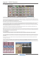
A1.2.1 New Internal Effects ..........................................................
16 stereo FPGA reverbs now added and permanently available.
Up to 32 other effects such as Delays, Choruses, Pitch Shifters and Audio Enhancers are also available.
The total number of other Effects which can be used simultaneously is dependant on combinations selected and limited by total resources.
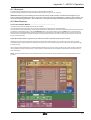
The effects are arranged in groups. Press an FX PRESET button on any existing effect or press the NEW button in the top left of the
Effects panel to view available effects. Effects groups are listed in the left section of the effects presets panel. Press a Group name to
view the selections available on the right of the panel. Press the effects name buttons to select, change or remove effects, in the same
way as on channel screens.
NOTE: When Effects names are greyed out, the maximum number of available effects has been reached.
Old Effects have been removed from SD7 (and will be removed from loaded sessions). The conversion from old to new FX presets
necessitated removing all presets prior to loading an old session, thus current presets which are not in the file are not preserved as they
would be normally.
When a preset is selected the effect is created and displayed without any signal or routing, signals can be routed to and from the effect
using standard input/output routing panels. It is still possible to create and route FX using the FX Output Button found at the output of
each channel type.
NOTE : All Effects created directly in the FX Rack are stereo. Mono effects can only be created using the FX Output button found on
channels.
A1-3
Appendix 1 - MACH 2 Operation
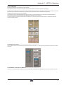
A1.2.2 Channel EQ Types .............................................................
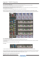
EQ bands can now switch between Reciprocal and Symmetrical Q (Previously, only reciprocal EQ was available).
Reciprocal EQ has a narrower Q setting on the cut curve than the boost curve.
Symmetrical EQ has identical Q settings on both boost and cut curves
Switching is done as a 2nd Function of the EQ Curve buttons which now have four possible states: Reciprocal Bell, Symmetrical Bell,
Reciprocal Shelf, Symmetrical Shelf.
A red highlight on the word recip or symm indicates which mode is active on which band.
NOTE: The output channel Pre-Insert EQ (See next section) the curves are all Bell type and are not switchable. On these
channels the Reciprocal/Symmetrical status can be switched using the Curve button without using the 2nd Function button.
A1.2.3 Dynamic EQ Details ...........................................................
Each band of EQ (Post Insert EQ on Output Channels) can be switched into Dynamic mode.
In a dynamic EQ module, the EQ adjustment is applied dynamically, based on the level of the incoming frequency relative to a predetermined threshold.
DiGiCo dynamic EQ can operate in two modes.. over or under.
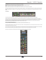
Over Mode
To place the dynamic module into Over mode, ensure that the Over indication below the threshold control is not illuminated.
When the signal entering the module passes the threshold, the EQ adjustment (as determined by the frequency and Q controls) starts to
be applied, up to a maximum adjustment, determined by the EQ band gain control. The manner in which the EQ adjustment is applied
once the threshold has been reached is determined by the attack, release and ratio controls.
Gain : Sets the maximum EQ adjustment that could be applied
Frequency / Q / Curve : Adjusts the EQ characteristics
A1-4
Appendix 1 - MACH 2 Operation
Threshold : Sets the threshold at which the EQ starts to be applied
Attack : controls how quickly the dynamic module responds to level passing the threshold
Release : adjusts how quickly the module responds to a fall in level
Ratio : controls how quickly the maximum adjustment is reached once the threshold level is passed.
Over Mode is generally used with a reduction in gain at a specific frequency, such that when the threshold is reached, a gradual reduction
of level at that frequency is applied. This could be used to control a change in tonal characteristics as a singer pushes their voice to sing
louder.
Under Mode
To place the dynamic module into Under mode, ensure that the Over indication below the threshold control is illuminated.
In under mode, the maximum EQ adjustment (as determined by the frequency, Q and band gain controls) is applied when the signal
entering the module is significantly below the threshold. As the signal level approaches the threshold, the EQ adjustment is reduced to the
point where there is no EQ being applied at the threshold. The manner in which the EQ adjustment is reduced as the signal level
approaches the threshold is determined by the attack, release and ratio controls.
A1.2.4 Output EQ Expansion .......................................................
All Output Channels now have 8 EQ bands, 4 pre-insert, 4 post-insert, and no Filters module.
There are 2 buttons at the top of each output channel strip, and also in the expanded EQ view, that are used to select which set of 4 bands
are assigned to the worksurface controls.
The pre-insert bands are all fixed as bell EQ’s and the post-insert bands have the same configuration as the standard input channel EQ [4
Band, each band switchable to Dynamic Mode, Reciprocal or Symmetrical Curve switching per band, Bell or Shelf]
HPF and LPF have been removed to allow processing to be allocated to these new bands of EQ.
A1-5
Appendix 1 - MACH 2 Operation
A1.2.5 Multi-Band Dynamics ........................................................
All hannels can have their Dynamics (Compressor) modules switched into Multi-band mode
On any channel (Input or Output), open the Dynamics Module, and expand the dynamic controls using the multi-band button.
Each band includes all of the parameters as those found in the single band compressor. The link function remains available for the whole
compressor, and is not assigned to any band. The bands can be switched on individually using the on buttons in the left-hand side of each
band, or together using the all on button to the display’s right.
Note: When any band is switched Off, that Band will not pass audio.
The crossover frequency between bands is controlled using the purple and red pots to the left of the hi and lo bands. Each crossover has
a range of 20Hz to 20kHz, and the crossover frequencies are displayed below each pot. Each band can be auditioned by pressing the
listen button below each gain pot which solo’s that band to the mix (not the solo buss), in effect temporarily switching off the other bands.
Pressing multi-band again returns the compressor to single-band.
The channel strip’s compressor threshold and gain controls adjustment all three bands’ controls, maintaining any relative offsets. The
individual controls are mapped to the assignable rotaries below the screen.
Note: Beyond the link function, the single and multi-band compressors have completely separate settings: No settings are copied between
them, and the settings of each remain unchanged when the other is active. Note also, however, that multi-band and single band dynamics
cannot both be active on one channel at the same time.
A1.2.6 Talkback .............................................................................
Talk to Aux features have been added : Aux Output Channels now include an assignable row of talk controls. Talk to Aux function
controllable independently per-channel, or from the Talkback panel which has a new Talk to Aux select list for each Talk button.
This is implemented as a new Talkback Input channel type which uses a single engine processing channel to provide the aux sends. This
new channel appears in a bank on its own for new sessions; when loading old sessions it is created automatically but not assigned to the
worksurface.
Note that old sessions which used the maximum channel processing will lose the last input channel when loaded to provide the audio
processing for Talk To Aux.
On the Aux Output channels hold one of the the Assign buttons next to the rows of assignable controls and then touch the talk section on
screen. This will assign the selected rotary control and switch to be Talk Level and Talk On/Off. A Dim Level control is also provided
per channel, operated as a 2 nd Function of the Talk Level. The Dim function reduces the level of the Aux program while the Talk function to
that Aux is active.
A1-6
Appendix 1 - MACH 2 Operation
A1.2.7 DiGiTubes ..........................................................................
This circuit emulates the non-linearities of a valve amplifier
at low levels the valve is almost linear and at high levels the valve starts to compress and exhibits “soft clipping”
The Drive control increases the input gain into the valve and automatically reduces the output gain so that the volume stays the same (like
gain tracking); the indicator shows how hard you are driving the valve and hence how much distortion is happening
The Bias control sets the symmetry of the distortion
At 0 the distortion is symmetrical and produces largely 2nd harmonic (and even) distortions, as the bias is increased the distortion
becomes more and more asymmetrical and starts adding 3rd (and odd) harmonic distortions
The result is the Bias controls the characteristics of the distortion; a lower Bias produces a softer distortion, whereas as higher Bias
produces a harder distortion.
A1.2.8 Audio I/O Ports ..................................................................
On the Audio I/O panel, it is now possible to change the Connection for racks 1 to 4, and freely assign any MADI or Optocore connection
to any rack.
A1.2.9 Master Screen Scroll Buttons ...........................................
These now scroll the Snapshots list, Matrix Inputs, the effects Rack, and Graphic EQs, depending on which panel is visible and on top
A1-7
Appendix 1 - MACH 2 Operation
A1.2.10 Session Report ................................................................
A Session Report button has been added under Files menu. This lists the session details on the master screen in an RTF compatible
format. The Save File button at the top left of this panel will save the report as the session filename suffixed with .rtf.
A1.2.11 Snapshots & MTC/SONY 9PIN........................................
Snapshots can now be programmed to send MMC messages, allowing control of external playback devices.
Within the snapshot scope section, the Transport Control button is now enabled. This opens the Snapshot Transport Control panel.
The panel lists all current session snapshots and allows entry, per snapshot, of the following MMC commands.
PLAY : Basic Play command. External device will play from current location
PLAY FROM : External device will play from specified time value
PLAY TO : External device will stop when the specified time is reached.
LOCATE TO : External device will Locate to specified time.
STOP : Basic Stop command. External device will stop.
Commands can be sent via MIDI or 9Pin, selected at the bottom of this panel.
NOTE : Correct MMC operation relies on a correctly configured MIDI system, with MTC from the external device connected to the console
MIDI Input. If this MTC connection is not present, the MMC snapshot system will not work.
A Transport Control panel is also provided in the Layout Menu. This provides a MTC readout of incoming MTC, and allows direct control
of the external device.
A1-8
Appendix 1 - MACH 2 Operation
It is now possible to program snapshots to fire at specific MTC Values.
Open the Snapshots Recall Times Panel. For each snapshot, enter an MTC value in the “Recall at” column. This functionality can be
switched on / off per snapshot by setting the tick in the Active column to the right of the Recall at column.
A1.2.12 Additional New Features .................................................
Current Engine, A or B, Indication on SD7 master screen if two engines detected.
Audio Master and Mirrored states added to Solo Meters on bridge.
Resetting Engine or Surfaces from on screen Menus now prompts for confirmation. Direct F11 / F12 key operation unchanged.
Channel Presets buttons on the Setup panels now close the Setup panel when displaying the Presets panel.
Routing panels remain open when switching between channels.
MiniRack device type is now permitted on the Audio I/O panel.
Can now scroll CG Members, Group Members, Snapshot Notes, Session Notes and Session Report by touch and drag (in opposite
direction to scroll bar).
Switching on a Channel Insert with no return path routed automatically opens the routing panel, and the Insert is not switched on. Make a
route, then switch the insert on.
Faders can now be switched between Free mode and Protected mode (Options Panel : Surface Tab). In Free mode, the faders can be
moved without recognising a touch {enabling them to be pushed with a pencil, or other object]. This is the original SD7 mode of fader
operation. In protected mode, the fader must sense human touch before they are allowed to move. This is like DiGiCo D-Series style fader
operation.
A1-9