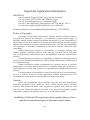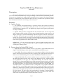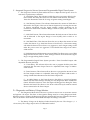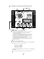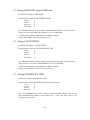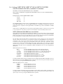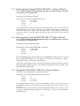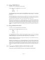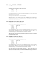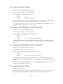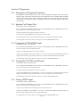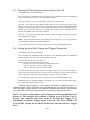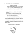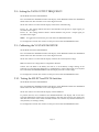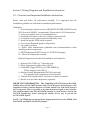
1
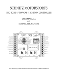
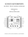
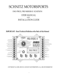
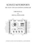
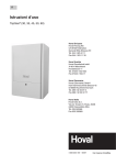
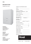
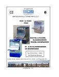
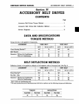
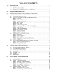
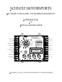
SCHNITZ MOTORSPORTS
DSC-TE2000, TOPGAS-2000 - TOP ELIMINATOR IGNITION
USER MANUAL
AND
INSTALLATION GUIDE
TOPGAS-2000
TOP ELIMINATOR
SCHNITZ
MOTORSPORTS
COIL 1,4 (OPTIONAL)
16GA YELLOW, PAGE 18
10
COIL 1,4 NEGATIVE
16GA WHITE, PAGE 18
11
TIMER OUTPUT (GROUND)
RECOMMEND 16GA , PAGE 21
12
NOS SOLENOID (GROUND)
16GA ORANGE, PAGE 20
13
ACTIVATION INPUT
20GA ORANGE, PAGE 20
14
CLUTCH SWITCH INPUT (2-STEP)
20GA YELLOW, PAGE 20
15
SHIFT INPUT
20GA GRAY, PAGE 22
16
SHIFT LIGHT (GROUND)
20GA BROWN, PAGE 22
SHIFT SOLENOID (GROUND)
20GA GREEN, PAGE 22
17
RUN
OR VOLTS SHIFT RPM
HIGH
ENGINE RPM AND
RPM
DIAGNOSTICS
LAUNCH
TIMER DELAY IN SECONDS
RPM
SHIFT STYLE &
SHIFT COUNTER
TIMER DURATION
ENGINE KILL
TIME
NOS DELAY TIME
IN SECONDS
NOS START PERCENT
BUILD RETARD
RETARD BUILD
IGNITION
CONTROLLER
NOS FINAL PERCENT
TIME IN SECONDS
ELECTRONIC
INITIAL NOS BUILD TIME
RETARD IN SECONDS
DSC-TE2000
PROGRAM
DSC-TE2000
0 1 2 3
18
1
9 8
4
5
6
7
0 1 2 3
.1
9 8
4
5
6
7
0 1 2 3
.01
9 8
4
5
6
7
0 1 2 3
.001
9 8
4
5
6
7
9
COIL 2,3 (OPTIONAL)
16GA PURPLE, PAGE 18
8
COIL 2,3 NEGATIVE
16GA BLUE, PAGE 18
7
GROUND
14GA BLACK, PAGE 18
6
TRIGGER (GROUND)
20GA BLACK, PAGE 18
5
TRIGGER +12V
20GA RED, PAGE 18
4
+12 VOLTS SWITCHED
16GA RED, PAGE 18
3
TACH OUTPUT
2
TRIGGER 2,3
20GA BLUE, PAGE 18
1
TRIGGER 1,4
20GA WHITE, PAGE 18
COPYRIGHT (C) 1998 BY, SCHNITZ MOTORSPORTS, ALL RIGHTS RESERVED
Important Application Information
IMPORTANT
Stock Crankshaft Trigger will NOT work with this Controller.
Use only DYNA (S) ® or DYNA PRO SERIES ® Trigger.
Use only a Dual Magnet Rotor for Crankshaft Trigger.
Use only .7ohm High Energy (Blue) Ignition Coils. Part #DC9-1, DC9-2
Use only Static Suppression Spark-plug Wires. Part #DW-800
All items listed above are available from Schnitz Racing. 1-219-728-9730
Notice of Copyright
Copyright (C) 1998 Schnitz Motorsports, Decatur, Indiana. All rights reserved.
Copyright law protects this document. It is unlawful to make copies, modify, or
distribute without written consent from Schnitz Motorsports. It is the responsibility of
the purchaser to follow all guidelines and safety procedures supplied with this product
and any other manufactures product used with this product. It is also the responsibility
of the purchaser to determine compatibility of this device with the vehicle and other
components.
Schnitz Motorsports assumes no responsibility for damages resulting from
accident, improper installation, misuse, abuse, improper operation, lack of reasonable
care, or all previously stated reasons due to incompatibility with other manufacturer's
products.
Schnitz Motorsports assumes no responsibility or liability for damages incurred
from the use of products manufactured or sold by Schnitz Motorsports on vehicles used
for competition racing.
Schnitz Motorsports neither recommends nor approves the use of products
manufactured or sold by Schnitz Motorsports on vehicles which may be driven on
public highways or roads, and assumes no responsibility for damages incurred from
such use.
It is the purchaser’s responsibility to check the state and local laws pertaining to
the use of Nitrous Oxide for racing applications. Schnitz Motorsports does not
recommend nor condone the use of its products for illegal street racing.
Caution
Follow all recommended safety guidelines from this and other manufacturer
installation guidelines. Never install any device, which pulsates nitrous solenoids
without a safety solenoid installed. Static suppression ignition wires must be used
with this unit! Mount the Ignition Controller as far away from secondary ignition
components (ignition coils, ignition wires, etc.) As is physically possible.
Installation of Schnitz Motorsports products signifies that you have
read this document and agree to the terms stated within.
Page 2
TopGas-2000 & Top Eliminator
Overview
Description:
The TopGas-2000 Ignition Controller is a highly integrated Digital Ignition System with
innovative features that enable today’s racing technology to be utilized to its maximum potential.
The system was designed to be simple while maintaining focus on features. This design technique
has led to a controller that can be installed in hours not days, provided other operational systems
have already been installed or are existing on the motorcycle.
Features:
A - Ignition System
1 - The controller uses digital circuitry to precisely monitor and control the Inductive
Type ignition drivers. This design enables precise and consistent ignition timing control
from High Energy Ignition Coils. The High-Energy design ensures ignition performance
for today’s technology.
2 – Ignition Timing Control is integrated into the controller. There are two stages and
types of timing retard available. The first stage or Initial Retard can range from 0 to 12
degrees. This stage is activated immediately when the Progressive Nitrous Timer System
is activated. The second stage was designed with a progressive timer that applies timing
control over a period of time. This stage is activated when the Nitrous Delay Timer times
out. The second stage of retard can range from 0 to 22 degrees and the Progressive Retard
Timer can be programmed from .200 to 9.000 seconds.
IMPORTANT – The first and second stages of retard are added together when used
together. Example: 1st stage at 4 degrees and 2nd stage at 12 degrees would provide a total
of 16 degrees of timing retard.
B – Features based on Engine RPM Control
1 – High RPM, This selection enables the user to program an Upper RPM Limit for the
engine. Valid RPM Range is from 3,000 to 16,000 RPM in 100-RPM Increments.
2 – Launch RPM, This selection enables the user to program the RPM at which the engine
and/or motorcycle leave starting line with. Applying +12V signal activates this stage of
RPM control. Valid RPM Range is from 3,000 to 16,000 RPM in 100-RPM Increments.
3 – Sequential Shift RPM, This selection enables the user to program the RPM at which
the Shift Light Output becomes active and/or Auto Shifting can occur. A different RPM
can Programmed for each gear, this is Sequential Shifting. The controller sequences
through the User Programmed Shift Points. Shift Sequencing begins when the Auto-Shift
Activation terminal is ON. The Shift Light Output is ON any time engine RPM is above
the Shift RPM Setting, and OFF whenever engine RPM falls below the Shift RPM. The
Auto-Shift System is very flexible and can be configured for all popular transmission
styles. There is a 1-second delay timer built in for the 1-2 shift, this helps to control short
shifts due to wheel spin off the line. A built-in and adjustable shift counter keeps track of
gear position and engine kill requirements. The shift counter also stops false shifting in
top gear position. The shift system can programmed for automatic or manual shifting.
The rider can do a manual or Shift Override at any time, even while in auto mode. The
shift counter is updated internally when manual shifts occur also.
Page 3
C – Integrated Progressive Nitrous System and Programmable Digital Timer System
1 – The Progressive Nitrous System enables the user to adjust the NOS power curve for
track and/or performance conditions.
A – NOS Delay Timer, This selection enables the user to program a delay for the
Start of NOS. The delay time can be set from 0.000 to 9.999 seconds. This delay
Timer also determines when the 2nd stage of ignition timing retard begins.
B – NOS Starting Percent, This selection determines the amount of NOS that is
delivered to the engine at the start of Nitrous Injection. By lowering the amount
of Nitrous introduced into the engine initially, traction problems can be
controlled to match track conditions. Range is from 0% (OFF), 20% to 100% in 1%
increments.
C – NOS Final Percent, This selection determines the final amount of Nitrous that
will be delivered to the engine. Range is from 0%(OFF), 20% to 100% in 1%
increments.
D – NOS Build Time, This selection allows the user to adjust the amount of time
it takes the Nitrous to go from Start Power to Final Power. A short time setting
will make the Nitrous Power Curve very aggressive. And a longer setting would
make the power curve less aggressive. Power Build Time ranges from .200 to
9.900 seconds.
E - NOS Minimum and Maximum Activation RPM, This allows user to set a RPM
Range that the NOS is active in. These settings will shut off the NOS if the engine
Bogs or is approaching the Rev Limiter
2 – The Programmable Digital Timer System provides a Time Controlled Output with
adjustable duration (On Time).
A – Timer Delay, This selection allows the user to program the delay time after
activation that the timer Output Turns On. Adjustable Time range of 0.000 to
9.999 seconds.
B – Timer Duration, This selection allows the user to program the amount of time
the Time Output remains on. Adjustable Time range of 0.000 to 9.999 seconds. A
setting of 0.000 Timer Duration turns the Timer Output OFF.
C – An added feature to the Timer System is the ability to control an Ignition
Stutter with the Timer Settings. Selecting it in the Diagnostics Menu enables this
feature. When this feature is active the engine will Stagger Fire during the Timer
Duration On Period. This allows a slow down of the motorcycle without external
devices connected to the Timer Output.
D – Diagnostics and Battery Voltage Monitor
1 – The Diagnostics Menu allows the user to perform various tests on activation circuits
and ignition coil output. The Static or Base ignition timing must be set using Diagnostic Mode.
When the engine is running the Diagnostic selection automatically becomes a Digital Tachometer.
This can be used to check Actual Launch RPM and adjust the settings as needed.
2 – The Battery Voltage can be displayed when desired by the user. The voltage is +/- .1
volt accuracy. The voltage output can be re-calibrated if needed.
Page 4
Table of Contents
Important Information and Cautions
Overview of Controller and Features
Section 1, Setting Controller Parameters
1.0 – The Basics of Setting Controller Parameters
1.1 – Setting HIGH RPM, Upper RPM Limit
1.2 – Setting LAUNCH RPM
1.3 – Setting ENGINE KILL TIME for Air Shift Applications
1.4 – Setting SHIFT RPM, SHIFT STYLE & SHIFT COUNTER
1.5 – Setting Ignition Timing INITIAL RETARD, 1st Stage
1.6 – Setting Ignition Timing BUILD RETARD, 2nd Stage
1.7 – Setting RETARD BUILD TIME for 2nd Stage
1.8 – Setting TIMER DELAY
1.9 – Setting TIMER DURATION
1.10 – Turning TIMED IGNITION STUTTER OPTION ON/OFF
1.11 – Setting NOS DELAY TIME
1.12 – Setting NOS START PERCENT
1.13 – Setting NOS FINAL PERCENT
1.14 - Setting NOS BUILD TIME
1.15 - Setting NOS MINIMUM ACTIVATION RPM
1.16 - Setting NOS MAXIMUM ACTIVATION RPM
1.17 – Checking Battery Voltage
Section 2, Diagnostics
2.0 – Description of Diagnostic Functions
2.1 – Ignition Coil Output Test
2.2 - Testing ACTIVATION Input
2.3– Testing CLUTCH Switch Input (Launch RPM Control)
2.4– Testing SHIFT Input
2.5– Turning the Timed Ignition Stutter Option On/Off
2.6 - Setting Ignition STATIC TIMING and Trigger Diagnostics
2.7 - Additional Information about Static Timing the Ignition
2.8 - Setting the TACH OUTPUT FREQUENCY
2.9 - Calibrating the VOLTAGE MONITOR
2.10 - Testing the SELECT and DATA Switches
Section 3, Wiring Diagrams and Installation Instructions
3.0 – Overview and Important Installation Instructions
3.1 – Connecting the Ignition Components
3.2 – Special Instructions for 4 Coil Systems
3.3 – Connecting the Nitrous Oxide System
3.4 – Connecting to the Timer Output
3.5 - Connecting the Shift Light and Auto Shift Components
3.6 - Electrical Specifications
Tech Tips
4.0- How to Run without NOS and/or AUTO-SHIFT
4.1 - Testing the Auto-Shift System and Some Tech Tips
Warranty Information
5.0 – Warranty
Page 2
Page 3, 4
Page 6
Page 7
Page 7
Page 7
Page 8
Page 9
Page 9
Page 9
Page 10
Page 10
Page 10
Page 11
Page 11
Page 11
Page 12
Page 12
Page 12
Page 12
Page 13
Page 13
Page 13
Page 13
Page 13
Page 14
Page 14
Page 15
Page 16
Page 16
Page 16
Page 17
Page 18
Page 19
Page 20
Page 21
Page 22
Page 23
Page 24
Page 24
Page 25
Page 5
1.0 - The Basics of Setting Controller Parameters
1 - Select Switch
TOPGAS-2000
TOP ELIMINATOR
SCHNITZ
MOTORSPORTS
RUN
SHIFT RPM
OR VOLTS
HIGH
RPM
ENGINE RPM AND
DIAGNOSTICS
LAUNCH
RPM
TIMER DELAY IN SECONDS
SHIFT STYLE &
SHIFT COUNTER
TIMER DURATION
ENGINE KILL
TIME
NOS DELAY TIME
IN SECONDS
NOS START PERCENT
BUILD RETARD
INITIAL
RETARD
IGNITION
CONTROLLER
NOS FINAL PERCENT
RETARD BUILD
TIME IN SECONDS
ELECTRONIC
NOS BUILD TIME
IN SECONDS
DSC-TE2000
PROGRAM
DSC-TE2000
0 1 2 3
1
9 8
4
5
6
7
0 1 2 3
.1
9 8
4
5
6
7
0 1 2 3
.01
9 8
4
5
6
7
0 1 2 3
.001
9 8
4
5
6
7
2 - Programming Switch
3 - Data Switches
Switch Descriptions and Functions
1 - Switch #1 is the FUNCTION SELECT SWITCH, This switch is used
to select which parameter is displayed and also selects that
parameter for programming.
2 - Switch #2 is the PROGRAM SWITCH, When this switch is pressed
down and held for 2-seconds the DATA switches will be read and
the settings will be programmed into the controller. If an
INVALID setting is read the controller will NOT save the setting and
will display an INVALID message on the display.
3 - Data Switches #3 are for entering RPM Data, Ignition Retard Data,
NOS Control Data, and for selecting various options as described
in the following pages.
Example Programming Sequence
Function Select Switch(#1) set to HIGH RPM (Switch pointing to HIGH RPM)
Data Switch 1 set at 1, .01 at 2, .001 at 5, .001 at 0
Data Switch 1 x 10,000 RPM
Data Switch .1 x 1,000 RPM
Data Switch .01 x 100 RPM
Data Switch .001 is Ignored
Pressing and holding PROGRAM Switch for 2-seconds will set the HIGH RPM
at 12,500 RPM.
Please refer to each of the following sections for setting all Functions.
Page 6
1.1– Setting HIGH RPM, Upper RPM Limit
Set SELECT Switch to HIGH RPM.
Example that would set HIGH RPM at 10,400
1 set at
1
.1 set at
0
.01 set at
4
.001 set at
0
Press PROGRAM Button until the display reads PROGRAM. Release the button and the
display will now read 10,400. HIGH RPM is now set at 10,400 RPM.
Valid RPM range 3,000 to 16,000 RPM in 100-RPM Increments.
Setting HIGH RPM to 0 will turn this function off.
1.2 - Setting LAUNCH RPM
Set SELECT Switch to LAUNCH RPM.
Example that would set LAUNCH RPM at 7,200
1 set at
0
.1 set at
7
.01 set at
2
.001 set at
0
Press PROGRAM Button until the display reads PROGRAM. Release the button and the
display will now read 7,200. LAUNCH RPM is now set at 7,200 RPM.
Valid RPM range 3,000 to 16,000 RPM in 100-RPM Increments.
Setting LAUNCH RPM to 0 will turn this function off.
1.3 – Setting ENGINE KILL TIME
Set SELECT Switch to ENGINE KILL TIME
Example that would set ENGINE KILL TIME at 85 milliseconds
1 set at
0
.1 set at
0
.01 set at
8
.001 set at
5
Press the PROGRAM button until the display reads PROGRAM. Display will now read
.085 and ENGINE KILL TIME is set at 85 milliseconds. Valid Time range .020 to .120
second in .001 increments.
Page 7
1.4 – Setting SHIFT RPM, SHIFT STYLE & SHIFT COUNTER
NOTE All Shift RPM’s MUST BE +/- 1,000 RPM of 1st Shift RPM!
Set SELECT Switch to the SHIFT RPM this is the 1st Shift RPM
When a NEW 1st Shift RPM is Programmed all Shift RPM’s will be set to the 1st Shift RPM Setting
Automatically.
Example that would set SHIFT RPM at 9,800
1 set at
0
.1 set at
9
.01 set at
8
.001 set at
0
Press PROGRAM Button until the display reads PROGRAM. Release the button and the display will now read
9,800. SHIFT LIGHT RPM is now set at 9,800 RPM. NOTE, IF the 1st Shift RPM is Programmed it will take a
couple of Seconds to Update the Following Shift RPM’s. Valid RPM range 3,000 to 16,000 RPM in 100-RPM
Increments.
NOTE: Only the 1st SHIFT RPM will be used until the ACTIVATION Terminal is Activated.. This is done with
a +12 volt signal. Please refer the next section for more information on the Auto-Shift System and its use.
NOTE: Additional Shift RPM’s are set as follows.
Set the SELECT Switch to SHIFT STYLE & SHIFT COUNTER Use the .001 DATA Switch to Select the Desired
Shift RPM to Set. You must turn the .001 DATA Switch to #2 to #5 positions to access the Sequential Shift RPM
Settings. The Display will show the which Shift Point you have selected. After Selecting the Desired Shift RPM,
It can be Programmed by using the Additional DATA Switches as outlined above.
The Auto-Shift is NOT activated until the Activation terminal is armed. Applying +12 volts to the terminal
does this. At this time of activation a 1-second timer will begin, NO AUTO SHIFTS will occur until this 1second timer is done. This prevents sudden shifts due to wheel spin at the initial launch. A shift override may
be activated at any time by applying +12V to the SHIFT Terminal. This is done with a shift button. A shift
override will be counted by the AUTO-SHIFT shift counter. Ignition KILL for the shifts are controlled
automatically by the controller. To use the SHIFT COUNTER with Manual shifting set the SHIFT STYLE as
outline below. Auto Shift must be ACTIVATED for SHIFT COUNTER to work even when using MANUAL
SHIFT Modes.
SHIFT STYLE options are as follows:
LITE
No AUTO SHIFTING. Engine kill for all shifts. Manual Shift Only.
1-2 LITE
No AUTO SHIFTING. Will NOT kill for 1-2 shift. Manual Shift Only.
1-2-3 LITE
No AUTO SHIFTING. Will NOT kill for 1-2, 2-3 shifts. Manual Shift Only.
AUTOLITE
No AUTO SHIFTING. Will NOT kill for all shifts. Manual Shift Only.
STANDARD
AUTO SHIFT ON. Will kill for all gears.
1-2 AUTO
AUTO SHIFT ON. Will NOT kill ignition for 1-2 shift.
1-2-3 AUTO
AUTO SHIFT ON. Will NOT kill ignition for 1-2-3 shifts.
FUL AUTO
AUTO SHIFT ON. Will NOT kill ignition for all shifts.
To change the SHIFT STYLE setting set the SELECT Switch to SHIFT STYLE & SHIFT COUNTER. Set the .001
DATA switch to 0. Pressing the PROGRAM button at this time will select the next option available. All option
may be viewed by pressing the PROGRAM button repeatedly.
SHIFT COUNTER options are as follows:
2-SPEED
No Auto-Shifts after 1 to 2 shift.
3-SPEED
No Auto-Shifts after 2 to 3 shift.
4-SPEED
No Auto-Shifts after 3 to 4 shift.
5-SPEED
No Auto-Shifts after 4 to 5 shift.
6-SPEED
No Auto-Shifts after 5 to 6 shift.
To change the SHIFT COUNTER setting set the SELECT Switch to SHIFT STYLE & SHIFT COUNTER. Set the
.001 DATA switch to 1. Pressing the PROGRAM button at this time will select the next option available. All
options may be viewed by pressing the PROGRAM button repeatedly.
Page 8
1.5 – Setting Ignition Timing INITIAL RETARD, 1st Stage of Retard
Note - Initial RETARD and Build RETARD Settings are Added together for Amount
of Total Ignition Timing RETARD.
Set SELECT Switch to INITIAL RETARD
Example that would set INITIAL RETARD to 6 degrees
1 set at
0 (not used)
.1 set at
0 (not used)
.01 set at
0
.001 set at
6
Press PROGRAM button until the display reads PROGRAM. Display will now read 6 DEG and
INITIAL RETARD is set to 6 degrees. Valid range 1 to 12 Degrees, 1Degree Increments. Setting to 0
will turn this function OFF. NOTE: This retard stage will turn on immediately when the NOS
Activation is turned on. (+12volts applied). The ignition retard will remain active until the NOS
system resets.
1.6 – Setting Ignition Timing BUILD RETARD, 2nd Stage of Retard
Note - Initial RETARD and Build RETARD Settings are Added together for Amount
of Total Ignition Timing RETARD.
Set SELECT Switch to BUILD RETARD
Example that would set BUILD RETARD to 14 degrees
1 set at
0 (not used)
.1 set at
0 (not used)
.01 set at
1
.001 set at
4
Press PROGRAM button until the display reads PROGRAM. Display will now read 14
DEG and BUILD RETARD is set to 14 degrees. Valid range 1 to 22 Degrees, 1 Degree
Increments. Setting to 0 will turn this function OFF.
NOTE: This retard stage will turn on when the NOS Delay Timer has timed out and the
NOS Solenoids have been turned on. The retard will progressively come on based on the
RETARD BUILD TIME setting.
1.7 – Setting RETARD BUILD TIME for 2nd Stage of Retard
Set SELECT Switch to RETARD BUILD TIME IN SECONDS
Example that would set RETARD BUILD TIME at 2.400 seconds
1 set at
2
.1 set at
4
.01 set at
0 (not used)
.001 set at
0 (not used)
Press PROGRAM button until the display reads PROGRAM. Display will now read 2.400 and
RETARD BUILD TIME is set at 2.400 seconds. Valid Time Range .200 to 9.900 seconds, .1 second
Increments.
Note: This setting determines the Ramp of IGNITION TIMING RETARD. A low setting i.e. (.200)
will make the TIMING RETARD very aggressive. A high setting i.e. (9.900) will make the TIMING
RETARD gradual.
Page 9
1.8 – Setting TIMER DELAY
Set SELECT Switch to TIMER DELAY IN SECONDS
Example that would set TIMER DELAY at 1.850 seconds
1 set at
1
.1 set at
8
.01 set at
5
.001 set at
0
Press PROGRAM button until the display reads PROGRAM. Display will now read 1.850 and
TIMER DELAY is set to 1.850 seconds. Valid range 0.000 to 9.999 seconds in .001 second
increments.
Note: This TIMER setting controls when the Timer Output turns on. The Delay Timer starts when
the ACTIVARION Input is activated. If the Clutch Input (2-Step) is activated the Timer Delay will
NOT begin until the Clutch Input is deactivated. This eliminates the need for relays.
Note: The Timer Output Driver is Connected Internally to the ACTIVATION Terminal. The
Output Driver will TURN OFF if the ACTVATION Terminal is NOT at +12V. This allows the
Timer Output to be Controlled by the Throttle Switch. The Timer Delay and Duration are NOT
affected by the ACTIVATION Input after the Initial Activation. Example - The NOS Timers wait
until the ACTVIATION Terminal is Re-Activated, The Timer Delay and Duration Continue to
Count.
1.9 - Setting TIMER DURATION
Set SELECT Switch to TIMER DURATION IN SECONDS
Example that would set TIMER DURATION at 1.400 seconds
1 set at
1
.1 set at
4
.01 set at
0
.001 set at
0
Press PROGRAM button until the display reads PROGRAM. Display will now read 1.400 and
TIMER DURATION is set to 1.400 seconds. Valid range 0.000 to 9.999 seconds in .001 second
increments. Setting this to 0.000 turns off the Timer Function even if it is ACTIVATED.
Note: This TIMER setting controls how Long the Timer Output stays on. The Duration Timer starts
when the Timer Delay has timed out.
Note: The Timer Output Driver is Connected Internally to the ACTIVATION Terminal. The
Output Driver will TURN OFF if the ACTVATION Terminal is NOT at +12V. This allows the
Timer Output to be Controlled by the Throttle Switch. The Timer Delay and Duration are NOT
affected by the ACTIVATION Input after the Initial Activation. Example - The NOS Timers wait
until the ACTVIATION Terminal is Re-Activated, The Timer Delay and Duration Continue to
Count.
1.10 – Turning the TIMED IGNITION STUTTER ON/OFF
Please refer to the DIAGNOSTICS Section for information on this feature.
Page 10
1.11 – Setting NOS DELAY TIMER
Set SELECT Switch to NOS DELAY TIME IN SECONDS
Example that would set NOS DELAY TIME at 1.250 seconds
1 set at
1
.1 set at
2
.01 set at
5
.001 set at
0
Press PROGRAM button until the display reads PROGRAM. Display will now read 1.250 and NOS
DELAY TIME is set to 1.250 seconds.
Valid range 0.000 to 9.999 seconds in .001 second increments.
Note: This is timer to delay the start of NOS. A time of 0.000 will allow the NOS to start
immediately when activated. Also the Ignition Timing BUILD Retard will NOT begin
until this Delay Timer has timed out.
1.12– Setting the NOS START PERCENT
Set SELECT Switch to NOS START PERCENT
Example that would set NOS START PERCENT at 34%
1 set at
0 (not used)
.1 set at
0
.01 set at
3
.001 set at
4
Press PROGRAM button until the display reads PROGRAM. Display will now read 34%
and NOS START PERCENT is set at 34%. Valid Percentage Range 10 to 100% in 1%
increments. Setting to 0% will turn NOS OFF even if NOS is Activated.
Note: This setting allows the starting POWER developed from the NOS to be controlled
for traction and other reasons.
1.13 – Setting NOS FINAL PERCENT
Set SELECT Switch to NOS FINAL PERCENT
Example that would set NOS FINAL PERCENT at 100%
1 set at
0 (not used)
1 set at
1
.01 set at
0
.001 set at
0
Press PROGRAM button until the display reads PROGRAM. Display will now read 100%
and NOS FINAL PERCENT is set at 100%. Valid Percentage Range 10 to 100%, 1%
Increments. Setting to 0% will turn NOS OFF even if NOS is Activated.
Note: This setting controls the maximum percentage of Nitrous Oxide that will be
delivered to the engine. A setting of less than 100% can be used. However, if FINAL% is
less than START% the NOS will remain at START% for the entire NOS cycle.
Page 11
1.14– Setting NOS BUILD TIME
Set SELECT Switch to NOS BUILD TIME IN SECONDS
Note: .001 Data Switch MUST be set at 0 to Set this Function.
Example that would set NOS BUILD TIME at 3.500 seconds
1 set at
3
.1 set at
5
.01 set at
0 (not used)
.001 set at
0 - Used to Select Build Time
Press PROGRAM button until the display reads PROGRAM. Display will now read 3.500 and NOS BUILD
TIME is set at 3.500 seconds. Valid Time Range .200 to 9.900 seconds in .1 second Increments.
Note: This setting determines how fast the NOS goes from START PERCENT to FINAL PERCENT. A shorter
BUILD TIME will make the NOS Power Curve more Aggressive.
1.15 – Setting NOS MINIMUM ACTIVATION RPM
Set SELECT Switch to NOS BUILD TIME IN SECONDS
Note: .001 Data Switch MUST be set at 1 to Set this Function.
Example that would set NOS
1 set at
.1 set at
.01 set at
.001 set at
MINIMUM ACTVATION RPM at 7,200
0
7
2
1 - Used to select NOS Minimum RPM Setting
Press PROGRAM Button until the display reads PROGRAM. Release the button and the display will now read
7,200. NOS will now be Disabled when RPM is below 7,200.Valid RPM range 3,000 to 16,000 RPM in 100-RPM
Increments.
1.16 – Setting NOS MAXIMUM ACTIVATION RPM
Set SELECT Switch to NOS BUILD TIME IN SECONDS
Note: .001 Data Switch MUST be set at 2 to Set this Function.
Example that would set NOS
1 set at
.1 set at
.01 set at
.001 set at
MAXIMUM ACTVATION RPM at 11,200
1
1
2
2 - Used to select NOS Maximum RPM Setting
Press PROGRAM Button until the display reads PROGRAM. Release the button and the display will now read
11,200. NOS will now be Disabled when RPM is over 11,200.Valid RPM range 3,000 to 16,000 RPM in 100-RPM
Increments.
Note: This Setting should be set to RPM that is Lower than the High RPM Setting. This will allow the NOS to
turn OFF before the Engine Rev Limiter is active.
1.16– Checking Battery Voltage
Set SELECT Switch to VOLTS
Battery Voltage will now be displayed. It is normal for the battery voltage reading to vary with the
engine running. This is due to the short duration high current demands of the ignition coils.
Page 12
Section 2, Diagnostics
2.0 – Description of Diagnostic Functions
The Diagnostics Functions will allow the user to test the output of the ignition coils, static time the
ignition system, and test the activation inputs. These functions are only available if NO crankshaft
movement has occurred. If the engine is running or has been turned over the diagnostics functions
cannot be accessed. When the engine is running this selection automatically displays engine RPM
on the display.
2.1 – Ignition Coil Output Test
Set the SELECT Switch to DIAGNOSTICS
Press and HOLD the PROGRAM Switch until display reads RELEASE. Release the PROGRAM Switch at this
time. The controller is now in the diagnostic mode.
To perform an ignition coil output test set the .001 switch to 0.
Press and release the PROGRAM switch. Each coil will be fired one time.
Caution: The ignition coils will produce a high voltage spark. Use appropriate methods for testing.
To exit diagnostics turn the .001 switch to 9. Then press and release the PROGRAM switch.
2.2– Testing the ACTIVATION Input
Set the SELECT Switch to DIAGNOSTICS
Press and HOLD the PROGRAM Switch until display reads RELEASE. Release the PROGRAM Switch at this
time. The controller is now in the diagnostic mode.
To perform ACTIVATION Input test set the .001 switch to 2.
At this time the DISPLAY will read ACTIVATE. If +12 volts is connected to the ACTIVATION terminal the
Display will flash the message ACTIVE. Use this test to verify the ACTIVATION switche(s) on the bike.
To exit diagnostics turn the .001 switch to 9. Then press and release the PROGRAM switch.
2.3 - Testing the CLUTCH Switch Input
Set the SELECT Switch to DIAGNOSTICS
Press and HOLD the PROGRAM Switch until display reads RELEASE. Release the PROGRAM Switch at this
time. The controller is now in the diagnostic mode.
To perform CLUTCH (2-step) Input test set the .001 switch to 3.
At this time the DISPLAY will read CLUTCH. If +12 volts is connected to the CLUTCH input terminal the
Display would flash the message ACTIVE. Use this test to verify clutch/2-step switches on the bike.
To exit diagnostics turn the .001 switch to 9. Then press and release the PROGRAM switch.
2.4 – Testing SHIFT Input
Set the SELECT Switch to DIAGNOSTICS
Press and HOLD the PROGRAM Switch until display reads RELEASE. Release the PROGRAM Switch at this
time. The controller is now in the diagnostic mode.
To perform Auto Shift & Timer Activation Input test set the .001 switch to 4.
At this time the DISPLAY will read SHIFT. If +12 volts is connected to the SHIFT terminal the Display will
flash the message ACTIVE. Use this test to verify the Shift switch.
To exit diagnostics turn the .001 switch to 9. Then press and release the PROGRAM switch.
Page 13
2.5 – Turning the Timed Ignition Stutter Option On/Off
Set the SELECT Switch to DIAGNOSTICS
Press and HOLD the PROGRAM Switch until display reads RELEASE. Release the PROGRAM
Switch at this time. The controller is now in the diagnostic mode.
Set the .001 switch to 5. At this time the display will read one of the following.
OPT. ON – This means the Timed Ignition Stutter Option is ON. By turning this option on the
Ignition will stagger fire the ignition coils for the amount of time set with the TIMER DURATION.
The ignition stutter will NOT begin until the TIMER DURATION has timed out. While the ignition
stutter is active each cylinder will fire once and skip one fire sequence. Please NOTE that all other
features and TIMERS remain active during this time.
OPT. OFF – This means the Timed Ignition Stutter is OFF. No ignition stagger fire will occur
during TIMER ACTIVATION.
NOTE – The Timer Output Terminal is NOT affected by this setting in any way. To toggle between
ON and OFF press and release the PROGRAM button.
To exit diagnostics turn the .001 switch to 9. Then press and release the PROGRAM switch.
2.6 – Setting Ignition Static Timing and Trigger Diagnostics
Set the SELECT Switch to DIAGNOSTICS
Press and HOLD the PROGRAM Switch until display reads RELEASE. Release the PROGRAM
Switch at this time. The controller is now in the diagnostic mode.
To set the Static Timing set the .001 switch to 1.
The display will read one of the following messages.
STATIC - This shows the controller is in Static Timing Mode
FIRE 1,4 - This shows when 1,4 cylinder will fire.
FIRE 2,3 - This shows when 2,3 cylinder will fire.
Note: Never Static Time the engine from the first trigger magnet. Only use the second magnet 90
degrees past the first magnet. Rotate the engine in the same direction as when running. The firing
point for the spark is at the point where the display changes to the message FIRE *, *.
To exit diagnostics turn the .001 switch to 9. Then press and release the PROGRAM switch.
IMPORTANT: This is the BASE TIMING for the ignition. If you do NOT understand this setting,
then contact YOUR engine builder for help.
Crankshaft Trigger Diagnostics - The controller will Display an ERROR Message if an
Intermittent Signal is Present from either of the Crankshaft Triggers. The controller will set the Error
Code if the Trigger is Faulty, this Error Code will Remain until the Program Button is Pressed and the
Error Code is removed. The Error Code will remain even if the Power is removed from the Box.
NOTE - To remove a Stored Error Code, Simply press the Program Button and
Release it. The controller will continue to operate even if an Error Code is
Present. The controller will keep trying to Re-Sync the Trigger if an
intermittent Crankshaft Trigger signal is present. The NOS, TIMER, and
AUTO-SHIFT System are not affected when the Controller Detects a Trigger
Error.
Page 14
2.4 - STATIC TIMING SHEET - SCHNITZ IGNITIONS
*** IMPORTANT INFORMATION ***
SETTING IGNITION STATIC TIMING
1 - INSTALL A DEGREE WHEEL AND LOCATE TOP DEAD CENTER AS
OUTLINED WITH THE DEGREE WHEEL INSTRUCTIONS.
IF YOU DO NOT HAVE A DEGREE WHEEL SCHNITZ RACING
CARRIES THIS ITEM.
THIS IS THE MOST ACCURATE WAY TO SET THE IGNITION
TIMING. IF YOU DO NOT KNOW THE IGNITION TIMING SPECIFICATIONS
FOR YOUR ENGINE, CONTACT YOUR ENGINE BUILDER FOR ASSISTANCE.
2 - ENTER DIAGNOSTIC MODE AS OUTLINED IN THE INSTRUCTION
MANUAL. SET THE .001 DATA SWITCH TO 1, THIS IS THE STATIC
TIMING MODE.
IMPORTANT: NEVER SET IGNITION TIMING BY ANY OTHER METHOD
THAN THAT WHICH IS OUTLINED BY THIS INSTRUCTION SHEET.
3 - AT THIS TIME THE DISPLAY SHOULD READ ONE OF THE FOLLOWING.
STATIC - INDICATING STATIC TIMING MODE.
FIRE 1,4 - THIS INDICATES #1,4 TRIGGER IS ACTIVE.
FIRE 2,3 - THIS INDICATES #2,3 TRIGGER IS ACTIVE.
TURN THE ENGINE THE DIRECTION OF NORMAL ROTATION.
NOTE: THERE ARE 2 MAGNETS ON THE TRIGGER ROTOR. THE DISPLAY
WILL INDICATE WHEN BOTH OF THESE MAGNETS ARE ALIGNED WITH
THE TRIGGER. YOU MUST USE THE SECOND MAGNET, THE SECOND
MAGNET IS THE ONE THAT FIRES THE IGNITION COIL.
PLEASE NOTE THAT THE DISPLAY WILL INDICATE THE PRECISE
TIME WHEN THE TRIGGER IS ACTIVATED BY THE ROTOR MAGNET. ADJUST
THE TRIGGER PLATE OR TRIGGER ASSEMBLY TO OBTAIN THE CORRECT
IGNITION TIMING.
EXAMPLE SHOWING 1ST AND 2ND TIMING MAGNETS
AT THIS TIME THE DISPLAY WOULD READ: FIRE 1,4
ROTATION
#2,3
ROTOR
2ND
1ST
TRIGGER PLATE ASSEMBLY
Page 15
#1,4
2.8 – Setting the TACH OUTPUT FREQUENCY
Set the SELECT Switch to DIAGNOSTICS
Press and HOLD the PROGRAM Switch until display reads RELEASE. Release the PROGRAM
Switch at this time. The controller is now in the diagnostic mode.
Set the .001 switch to 6. At this time the display will read one of the following.
TACH X2 - This setting indicates that the TACH OUTPUT will provide 2 output signals per
revolution of the engine.
TACH X1 - This setting indicates that the TACH OUTPUT will provide 1 output signal per
revolution of the engine.
NOTE – To toggle between X2 and X1 press and release the PROGRAM button.
To exit diagnostics turn the .001 switch to 9. Then press and release the PROGRAM switch.
2.9 - Calibrating the VOLTAGE MONITOR
Set the SELECT Switch to DIAGNOSTICS
Press and HOLD the PROGRAM Switch until display reads RELEASE. Release the PROGRAM
Switch at this time. The controller is now in the diagnostic mode.
Set the .001 switch to 7. At this time the display will show the Current System Voltage.
Note: You will need a Voltage Meter to complete this function.
Connect the Volt Meter to the Battery and turn it on. If the Battery Voltage reading on the
Controller is Correct then Exit Diagnostics as outlined below. If the Voltage needs to be adjusted
Press and Release the PROGRAM Button until the Display reads the Correct Volatge.
To exit diagnostics turn the .001 switch to 9. Then press and release the PROGRAM switch.
2.10 - Testing the SELECT and DATA Switches
Set the SELECT Switch to DIAGNOSTICS
Press and HOLD the PROGRAM Switch until display reads RELEASE. Release the PROGRAM
Switch at this time. The controller is now in the diagnostic mode.
Set the .001 switch to 8. At this time the display will read SWITCH.
To perform the Test, Press and Release the PROGRAM Button. The display will at first show
Copyright Information and the Date of Programming. After this these messages the display will
show the current states of the Select and Data Switches. The switches may rotated at this time to
verify that they are reading correctly.
To exit diagnostics turn the .001 switch to 9. Then press and release the PROGRAM switch.
Page 16
Section 3, Wiring Diagrams and Installation Instructions
3.0 – Overview and Important Installation Instructions
Please read and follow all instructions carefully. It is important that the
installation guidelines be followed for maximum performance.
Guidelines:
1 - If Stock Ignition Switch is used a SEPARATE POWER SOURCE for the
NOS System is HIGHLY recommended. Please refer to NOS Instructions.
2 - Use a good quality wire of recommended size.
3 - Solder all connectors to the wire, crimped connectors fail!
4 - Use shrink wrap to protect exposed terminals/wires.
5 - Install the proper FUSE where required.
6 - Use only the Required Ignition components.
7 - Use quality switches.
8 - Follow other manufacturer guidelines and recommendations when
installing related components.
9 - NEVER disregard SAFETY and/or CAUTION Warnings!
10 - Mount all components correctly.
Related Components Needed for Installation and Operation
1 - Ignition Coils, DYNA (r) .7 ohm blue coils.
2 - Static Suppression Ignition Wires ONLY!
3 - Crankshaft Trigger, DYNA (s) or PRO SERIES (r)
(DUAL magnet rotor ONLY!)
4 - Nitrous System, Recommended NOS Kit (optional).
(Use genuine NOS components for best results)
5 – Throttle with Switch built in. Activation switches as needed.
6 - Electric over air shift components (optional).
IMPORTANT INFORMATION - The Controller will NOT turn on the NOS,
TIMER, and\or AUTO-SHIFT Systems if the CLUTCH Input is Active(2-Step is ON).
Installation of this Controller Requires a Throttle Switch even if the NOS System is
NOT being used. This is to provide an Accurate Activation Signal to the Controller.
This method requires that LAUNCH RPM function be used! Always Activate the
CLUTCH Input(2-step) before opening the throttle all the way to provide the
ACTIVATION Signal !
NOTE - The TE2000 has an internal Noise Suppression Diode for the TIMER, NOS
SOLENOID, and SHIFT SOLENOID Outputs.
Page 17
3.1 - Connecting the Ignition Components
NOTICE: If Installing a 4-Coil System READ PAGE 19
TOPGAS-2000
TOP ELIMINATOR
SCHNITZ
MOTORSPORTS
COIL 1,4(OPTIONAL)
COIL 1,4 NEGATIVE
TIMER OUTPUT (GROUND)
PAGE 21
10
11
12
13
ACTIVATION INPUT
PAGE 20
14
CLUTCH SWITCH INPUT(2-STEP)
PAGE 20
15
SHIFT INPUT
PAGE 22
16
SHIFT LIGHT (GROUND)
PAGE 22
17
SHIFT SOLENOID (GROUND)
PAGE 22
18
OR VOLTS
HIGH
RPM
SHIFT RPM
ENGINE RPM AND
TIMER DELAY IN SECONDS
TIMER DURATION
ENGINE KILL
TIME
NOS DELAY TIME
IN SECONDS
NOS START PERCENT
BUILD RETARD
RETARD BUILD
INITIAL
RETARD
IGNITION
CONTROLLER
NOS FINAL PERCENT
TIME IN SECONDS
ELECTRONIC
DIAGNOSTICS
LAUNCH
RPM
SHIFT STYLE &
SHIFT COUNTER
NOS BUILD TIME
IN SECONDS
DSC-TG2000
PROGRAM
DSC-TG2000
0 1 2 3
1
9 8
4
5
6
7
0 1 2 3
.1
9 8
4
5
6
7
0 1 2 3
9 8
.01
0 1 2 3
4
5
6
7
9 8
.001
4
5
6
7
COIL 2,3 (OPTIONAL)
8
COIL 2,3 NEGATIVE
7
GROUND
6
TRIGGER GROUND
5
TRIGGER +12V
4
+12 VOLTS SWITCHED
3
TACH OUTPUT
2
TRIGGER 2,3
1
TRIGGER 1,4
RIGHT
TERMINAL
IMPORTANT: MUST USE A DUAL MAGNET
ROTOR AND .7 OHM (BLUE) IGNITION COILS!
USE ONLY DYNA(R) DW-800 SUPPRESSION WIRES!
RED WIRE, 16GA, +12V FROM IGNITION SWITCH
TRIGGER 1,4 WHITE 20GA
TRIGGER 2,3 BLUE 20GA
INPUT
OUTPUT
TRIGGER +12V, RED 20GA
IGNITION SWITCH
PART# SCH-0048
TO BATTERY + TERMINAL
16 GA
FUSE 10A
TECH TIP - RUN GROUND WIRE FROM CONTROLLER
STRAIGHT TO THE BATTERY NEG. USE ONLY ONE
GROUND WIRE TO ENGINE. WHEN CONNECTING A
GROUND LEAD FOR ITEMS NOT CONNECTED TO
CONTROLLER ROUTE THE GROUND WIRE DIRECTLY
TO THE BATERY NEG. TERMINAL.
T2
T3
NEG
12 VOLT
BATTERY
NOTE:
WIRING FOR PRO SERIES(R) PICKUP
T1 - RED (+12V SWITCHED)
T2 - BLACK (PICKUP GND)
T3 - WHITE (TRIGGER 1,4)
T4 - BLUE (TRIGGER 2,3)
ENGINE GROUND
ONE GROUND WIRE TO ENGINE
COIL POSITIVE, RED 16 GA
1ST COIL
.7 OHM BLUE COIL
2ND COIL
.7 OHM BLUE COIL
(OPTIONAL)
FUSE 20A
CAUTION: REMOVE COIL 20A FUSE(S)
WHEN NOT IN USE. COILS MAY BE
WIRED THROUGH IGNITION SWITCH
ALSO, HOWEVER, THE METHOD SHOWN
IS PREFERRED FOR EXTREME RACE
CONDITIONS.
Page 18
1ST COIL
.7 OHM BLUE COIL
2ND COIL
.7 OHM BLUE COIL
(OPTIONAL)
COIL 2,3 NEGATIVE TERMINAL, BLUE 16 GA
DYNA S (R)
RED
POS+
PICKUP GROUND
BLACK. 20GA
T4
T1
BLACK
WHITE
FUSE 20A
COIL 1,4 NEGATIVE TERMINAL, WHITE 16 GA
16 GA
COIL 2,3 NEGATIVE TERMINAL(4 COIL SYSTEM ONLY), PURPLE 16 GA
COIL 1,4 NEGATIVE TERMINAL(4 COIL SYSTEM ONLY), YELLOW 16 GA
LEFT
TERMINAL
9
GROUND, BLACK 14 GA
NOS SOLENOID (GROUND)
PAGE 20
RUN
3.2 - Special Instructions for 4 Coil Systems
IMPORTANT
Use Only Carbon Core Ignition Wires
With a Resistance of 3000 Ohms
Per Foot Minimum.
On Dual Plug Systems, Never Connect BOTH
OUTPUTS(Sparkplug Wires) to One Cylinder.
Example: Do NOT Connect 1st Coil 1,4 Both
Wires to Cylinder #1.
The CORRECT Way To Wire the Ignition
Coils is Shown Below.
1st Coil, Cyl. 1,4
.7 Ohm Blue Coil
2nd Coil, Cyl. 1,4
1st Coil 1,4 WHITE
Cylinder #2
.7 Ohm Blue Coil
Cylinder #3
Cylinder #4
Cylinder #1
1st Coil, Cyl. 2,3
.7 Ohm Blue Coil
2nd Coil 1,4 YELLOW
2nd Coil, Cyl. 2,3
.7 Ohm Blue Coil
1st Coil 2,3 BLUE
Page 19
2nd Coil 2,3 PURPLE
3.3 - Connecting the Nitrous Oxide System
NOTICE: ALL DIODES, CAPACITORS, AND FILTERS FROM PREVIOUS NOS INSTALLATIONS MUST BE
REMOVED! FAILURE TO DO SO WILL RESULT IN UNDISIRABLE OPERATION OF THIS CONTROLLER.
NOTE: NOS TIMERS WILL NOT BEGIN UNTIL 2-STEP IS OFF. THIS ALLOWS THE SYSTEM TO OPERATE
WITHOUT RELAYS. IF +12 VOLTS IS APLLIED TO THE ACTIVATION TERMINAL WITHOUT THE
CLUTCH INPUT ACTIVATED THE NOS, TIMER, AND AUTO-SHIFT SYSTEMS WILL TURN ON.
TOPGAS-2000
TOP ELIMINATOR
SCHNITZ
MOTORSPORTS
COIL 1,4 (OPTIONAL)
PAGE 18
CLUTCH SWITCH INPUT(2-STEP), YELLOW 20 GA
COIL 1,4 NEGATIVE
PAGE 18
10
11
TIMER OUTPUT (GROUND)
PAGE 21
12
NOS SOLENOID (GROUND)
13
ACTIVATION INPUT
14
CLUTCH SWITCH INPUT (2-STEP)
15
SHIFT INPUT
PAGE 22
16
SHIFT LIGHT (GROUND)
PAGE 22
17
SHIFT SOLENOID (GROUND)
PAGE 22
18
RUN
OR VOLTS
HIGH
RPM
SHIFT RPM
ENGINE RPM AND
LAUNCH
RPM
TIMER DELAY IN SECONDS
SHIFT STYLE &
SHIFT COUNTER
TIMER DURATION
ENGINE KILL
TIME
NOS DELAY TIME
IN SECONDS
NOS START PERCENT
BUILD RETARD
RETARD BUILD
INITIAL
RETARD
IGNITION
CONTROLLER
NOS FINAL PERCENT
TIME IN SECONDS
ELECTRONIC
DIAGNOSTICS
NOS BUILD TIME
IN SECONDS
DSC-TE2000
PROGRAM
DSC-TE2000
0 1 2 3
1
9 8
4
5
6
7
0 1 2 3
9 8
.1
0 1 2 3
4
5
6
7
.01
9 8
4
5
6
7
9 8
4
5
6
7
8
COIL 2,3 NEGATIVE
PAGE 18
7
GROUND
PAGE 18
6
TRIGGER GROUND
PAGE 18
5
TRIGGER +12V
PAGE 18
4
+12 VOLTS SWITCHED
PAGE 18
3
TACH OUTPUT
TRIGGER 2,3
PAGE 18
1
LEFT
2-STEP BUTTON
COIL 2,3 (OPTIONAL)
PAGE 18
2
0 1 2 3
.001
9
TRIGGER 1,4
PAGE 18
RIGHT
CONNECT TO IGNTION SWITCH OUTPUT
PAGE 18
16GA BLACK
PART # SCH0070
16GA RED
ACTIVATION INPUT, ORANGE 20 GA
NEGATIVE
POS+
NEG
12 VOLT
BATTERY
NOS
FUEL
PUMP
ENGINE GROUND
SEE PAGE 18
POSITIVE
FUSE 20A
16GA RED
16GA RED
FUSE 20A
NOS ARMING SWITCH
DOUBLE POLE, SINGLE THROW
PART# SCH-0049
THROTTLE ACTIVATED MICROSWITCH
SWITCH ON ONLY WHEN THROTTLE
IS WIDE OPEN. SWITCHED THROTTLE
PART# 1-0068 OR FBG3000
NOTE - THIS SYSTEM IS DESIGNED TO BE USED WITH A THROTTLE SWITCH EVEN IF
NOS SYSTEM IS NOT CONNECTED. IF NO NOS SYSTEM IS INSTALLED USE A TOGGLE
SWITCH TO ARM THE ACTVATION SYSTEM(PROVIDES +12V FOR THROTTLE SWITCH).
BY USING A THROTTLE SWITCH NO RELAYS ARE NEEDED. CONTROLLER IGNORES
OTHER INPUTS WHILE 2-STEP IS ON(CLUTCTH INPUT ACTIVE).
NOTE: NOS SYSTEM CAN BE TURNED OFF BY
SETTING EITHER START% OR FINAL% T0 0%
THIS WILL ALLOW THE TIMER AND SHIFT
SYSTEM TO BE ACTIVATED FROM THROTTLE
SWITCH EVEN WHEN NO NOS IS DESIRED.
FUEL
SOLENOID
Page 20
NOS
SOLENOID
SAFETY
SOLENOID
GROUND
3.4 - Connecting to the Timer Output
NOTE: TIMERS WILL NOT BEGIN UNTIL 2-STEP IS OFF. THIS ALLOWS THE SYSTEM TO OPERATE
WITHOUT RELAYS. IF +12 VOLTS IS APLLIED TO THE ACTIVATION TERMINAL WITHOUT THE
CLUTCH INPUT ACTIVATED THE NOS, TIMER, AND AUTO-SHIFT SYSTEMS WILL TURN ON.
SCHNITZ
MOTORSPORTS
COIL 1,4 (OPTIONAL)
PAGE 18
10
COIL 1,4 NEGATIVE
PAGE 18
11
TIMER OUTPUT (GROUND)
12
NOS SOLENOID (GROUND)
PAGE 20
13
RUN
CLUTCH INPUT (2-STEP)
PAGE 20
15
SHIFT INPUT
PAGE 22
16
SHIFT LIGHT (GROUND)
PAGE 22
17
SHIFT SOLENOID (GROUND)
PAGE 22
18
9
COIL 2,3 (OPTIONAL)
PAGE 18
ELECTRONIC
8
COIL 2,3 NEGATIVE
PAGE 18
7
GROUND
PAGE 18
6
TRIGGER GROUND
PAGE 18
OR VOLTS SHIFT RPM
HIGH
ENGINE RPM AND
RPM
DIAGNOSTICS
LAUNCH
TIMER DELAY IN SECONDS
RPM
SHIFT STYLE &
SHIFT COUNTER
TIMER DURATION
ENGINE KILL
TIME
NOS DELAY TIME
IN SECONDS
NOS START PERCENT
BUILD RETARD
RETARD BUILD
IGNITION
CONTROLLER
NOS FINAL PERCENT
TIME IN SECONDS
INITIAL NOS BUILD TIME
RETARD IN SECONDS
14
ACTIVATION INPUT
PAGE 20
TOPGAS-2000
TOP ELIMINATOR
DSC-TE2000
PROGRAM
DSC-TE2000
0 1 2 3
1
9 8
4
5
6
7
0 1 2 3
.1
9 8
4
5
6
7
0 1 2 3
.01
9 8
4
5
6
7
0 1 2 3
.001
LEFT
9 8
4
5
6
7
5
TRIGGER +12V
PAGE 18
4
+12 VOLTS SWITCHED
PAGE 18
3
TACH OUTPUT
2
TRIGGER 2,3
PAGE 18
1
TRIGGER 1,4
PAGE 18
RIGHT
SEE PAGE 20 FOR ACTIVATION INPUT DETAILS
NOTE - THIS SYSTEM IS DESIGNED TO BE USED WITH A THROTTLE SWITCH EVEN IF
NOS SYSTEM IS NOT CONNECTED. IF NO NOS SYSTEM IS INSTALLED USE A TOGGLE
SWITCH TO ARM THE ACTVATION SYSTEM(PROVIDES +12V FOR THROTTLE SWITCH).
BY USING A THROTTLE SWITCH NO RELAYS ARE NEEDED. CONTROLLER IGNORES
OTHER INPUTS WHILE 2-STEP IS ON(CLUTCTH INPUT ACTIVE).
CONNECT TO IGNITION SWITCH OUTPUT
FUSE 5A
20 GA RED
OPTIONAL: CONNECT TO SEPARATE
SWITCH FOR ARMING TIMER CONTROLLED
DEVICES
TIMER OUTPUT (GROUND)
AIR SOLENOID
FOR THROTTLE
STOP
NOTE - TIMER OUTPUT CAN SINK UP TO 30AMPS. TIMER OUTPUT WILL TURN OFF
WHEN ACTIVATION INPUT IS TURNED OFF(IF YOU LET OUT OF THE THROTTLE)
NOS TIMERS WILL WAIT IF ACTIVATION IS TURNED OFF AFTER ARMING, TIMER
SYSTEM WILL CONTINUE TO COUNT DOWN(ONLY THE OUTPUT IS TURNED OFF).
Page 21
3.5 - Connecting the Auto Shift Components
NOTE: TIMERS WILL NOT BEGIN UNTIL 2-STEP IS OFF. THIS ALLOWS THE SYSTEM TO OPERATE
WITHOUT RELAYS. IF +12 VOLTS IS APLLIED TO THE ACTIVATION TERMINAL WITHOUT THE
CLUTCH INPUT ACTIVATED THE NOS, TIMER, AND AUTO-SHIFT SYSTEMS WILL TURN ON.
TOPGAS-2000
TOP ELIMINATOR
SCHNITZ
MOTORSPORTS
COIL 1,4 (OPTIONAL)
PAGE 18
10
COIL 1,4 NEGATIVE
PAGE 18
11
TIMER OUTPUT (GROUND)
PAGE 21
12
NOS SOLENOID (GROUND)
PAGE 20
13
ACTIVATION INPUT
PAGE 20
14
CLUTCH INPUT(2-STEP)
PAGE 20
15
SHIFT INPUT
16
SHIFT LIGHT (GROUND)
17
SHIFT SLOENOID (GROUND)
RUN
OR VOLTS
HIGH
RPM
ENGINE RPM AND
DIAGNOSTICS
LAUNCH
RPM
TIMER DELAY IN SECONDS
SHIFT STYLE &
SHIFT COUNTER
TIMER DURATION
ENGINE KILL
TIME
NOS DELAY TIME
IN SECONDS
NOS START PERCENT
BUILD RETARD
RETARD BUILD
INITIAL
RETARD
ELECTRONIC
IGNITION
CONTROLLER
NOS FINAL PERCENT
TIME IN SECONDS
NOS BUILD TIME
IN SECONDS
DSC-TE2000
PROGRAM
DSC-TE2000
0 1 2 3
18
1
MANUAL SHIFT SWITCH, GRAY 20 GA
SHIFT RPM
9 8
4
5
6
7
0 1 2 3
.1
9 8
4
5
6
7
0 1 2 3
.01
LEFT
9 8
4
5
6
7
0 1 2 3
.001
9 8
4
5
6
7
9
COIL 2,3 (OPTIONAL)
PAGE 18
8
COIL 2,3 NEGATIVE
PAGE 18
7
GROUND
PAGE 18
6
TRIGGER GROUND
PAGE 18
5
TRIGGER +12V
PAGE 18
4
+12VOLTS SWITCHED
PAGE 18
3
TACH OUTPUT
2
TRIGGER 2,3
PAGE 18
1
TRIGGER 1,4
PAGE 18
RIGHT
SEE PAGE 20 FOR ACTIVATION INPUT DETAILS
NOTE - THIS SYSTEM IS DESIGNED TO BE USED WITH A THROTTLE SWITCH EVEN IF
NOS SYSTEM IS NOT CONNECTED. IF NO NOS SYSTEM IS INSTALLED USE A TOGGLE
SWITCH TO ARM THE ACTVATION SYSTEM(PROVIDES +12V FOR THROTTLE SWITCH).
BY USING A THROTTLE SWITCH NO RELAYS ARE NEEDED. CONTROLLER IGNORES
OTHER INPUTS WHILE 2-STEP IS ON(CLUTCTH INPUT ACTIVE).
FUSE 5A
CONNECT TO IGNITION SWITCH OUTPUT
SHIFT SOLENOID & SHIFT LIGHT POSITIVE, 20 GA RED
OPTIONAL: CONNECT TO SEPARATE
SWITCH FOR ARMING SHIFT SYSTEM
MANUAL SHIFT SWITCH
NORMALY OPEN PUSBUTTON
RECOMMEND MPS PRO SERIES
AIR SHIFT
SOLENOID
SHIFT LIGHT
SHIFT SOLENOID GROUND, 20 GA GREEN
SHIFT LIGHT GROUND, 20 GA BROWN
NOTE - NO NOISE SUPPRESSION DIODE NEEDED FOR SHIFT SOLENOID.
NOISE SUPPRESSION DIODE IS INTERNAL. ALSO THE TIMER AND NOS
OUTPUTS HAVE INTERNAL NOISE FILTERS.
Page 22
3.6 - Electrical Specifications
Power Requirements:
+12V to 14.5V Supply Voltage
Negative Ground
Minimum of 9 volts while cranking engine.
Ignition Current Draw:
2 amps at 5,000 RPM
5 amps at 10,000 + RPM
Note: If Battery Voltage falls below 11 volts the controller will increase the Amperage to
the Coils to provide Maximum Spark Energy. The controller will shut off if Battery
Voltage continues to drop.
Activation Input:
+12 volts at 5mA
Clutch Input:
+12 volts at 5mA
Shift Input:
+12 volts at 5mA
NOS Output:
30 Amp Maximum Current Draw for 20seconds.
Output provides a ground signal for the NOS and Fuel
Solenoids. Active Noise Suppression components are
internal and NO external filters are needed.
Timer Output:
30 Amp Maximum Current Draw for 20seconds.
Output provides a ground signal for the NOS and Fuel
Solenoids. Active Noise Suppression components are
internal and NO external filters are needed.
Note: NOS and Timer Outputs will Turn OFF if the Activation Signal is removed
During Operation. The NOS Timers will wait during this period, however, the Timer
System will continue to Count Down.
Shift Solenoid Output:
2 Amp Maximum Current Draw, Provides Ground Signal.
Noise Suppression Diode is Internal and NO Diode is
needed if the Shift Solenoid Output is used to operate the
Shift Solenoid.
Shift Light Output:
2 Amp Maximum Current Draw, Provides Ground Signal.
Warning - Never connect any Relays or Solenoids to this
Output. Permanent Damage may Occur to Controller!
Page 23
Tech Tips
4.0 - How to Run without NOS and/or AUTO-SHIFT
1 - To disable the NOS system. Program either the Start or Final NOS Percent to
0. The Display will then read OFF when set to Start %or End %. Be SURE to turn OFF
the Ignition Retard also. This is done by Setting the Initial and Build Retard Degree’s to
0. By setting the NOS and Retard to OFF the user can still activate the Auto-Shift System
and operate with no NOS.
2 - NOTE: When using Manual Shift Mode the Auto-Shift Activation must be
enabled for the Engine Kill and Shift Counter to operate correctly. Please refer to the
Section about setting the Auto-Shift for more information.
5.1 - Testing the Auto-Shift System and Some Shift Tech Tips
1 - The Auto-Shift System can be Tested with the Motorcycle Stationary. Remove
the Shift Cylinder Linkage from the Shift Shaft. You MUST DO THIS! Verify that there is
Air Pressure in the System. Raise the Back Tire off from the ground and support the
motorcycle in a safe manner.
2 - Verify that the Desired Shift Style is selected. To help detect engine kill set the
Kill Time to .150 Second. Set the Shift RPM to a low Setting i.e.(5,000 RPM). Prepare the
Motorcycle for Starting. Make sure Fuel and Oil are OK, Have the Starter Handy. Turn
on the Controller and all other Arming Switches needed for Auto-Shift Activation. At
this time Twist the Throttle wide open to Arm the Auto-Shift System. If your bike does
not use a Throttle switch then use the correct Arming Switch for your application. Be
sure to release the throttle and Start the Engine. At this time you can give the throttle a
quick twist and verify that the Shift Light and Shift Cylinder work for each gear change.
You should be able to hear the Engine Kill when it is needed for the gear change. This is
based on the Shift Style Setting. The Controller will RESET the Auto-Shift System after
20 seconds. This is why you must be prepared to run this test.
3 - After testing the System re-connect the Shift Cylinder Linkage, Set the Proper
Shift RPM , and Engine Kill Time.
Note - Some tracks are to rough to use the Auto-Shift System. When the rear bounces
under acceleration the Engine will Rev Quickly and cause false Shifts to Occur. These
will increment the shift counter also. This can cause the Engine Kill sequence to be
altered and NOT function properly. Also the Final Shift will NOT be performed because
the controller thinks that it has already shifted all the gears.
If you are having trouble with the Auto-Shifter and you are also having a great deal of
wheel spin off from the line you will need to correct the wheel spin problem. The
controller cannot correct for this type error conditions.
Please Note that if you are Manual shifting and using the shift counter the Counter will
Increment when you push the shift button. The Counter will NOT Increment if the Shift
Light is on when you push the button and the Engine RPM Does NOT fall below the
Next Shift RPM. If you Push the Shift Button before the Shift Light comes on(short shift)
the counter will be incremented regardless of the Engine RPM. Even if the Transmission
does NOT shift due to wheel spin or other error conditions. The Engine Kill Pattern will
follow the Shift Counter.
Page 24
Warranty Information
5.0 – Warranty
Schnitz Motorsports warrants to the original purchaser that the
Electronic Ignition Controller shall be free from defects in parts and
workmanship under normal use for 90 days from the date of purchase.
Schnitz Motorsports obligation under this warranty is limited to
the repair or replacement of any component found to be defective when
returned postpaid to Schnitz Motorsports. The Controller must be
returned with evidence of place and date of purchase or warranty will be
void. The warranty will not apply if the Electronic Ignition Controller has
been installed incorrectly, repaired, damaged, or tampered with by
misuse, negligence or accident.
Phone 1-219-728-9457
Page 25