1
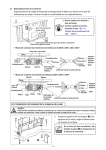
LON Power Supply LPS 133
Art.-no.: MTN884019
User Manual
LON Power Supply LPS133
Art. no. MTN884019
Content
1.
2.
3.
4.
5.
Description ......................................................................................................... 2
Function.............................................................................................................. 3
Mounting............................................................................................................. 3
Remarks.............................................................................................................. 4
Technical Data.................................................................................................... 5
Date:19.08.2010
Changes possible
Page 1 of 5
LON Power Supply LPS 133
Art.-no.: MTN884019
1.
Description
•
•
•
•
•
•
•
power supply for devices with Link Power Transceivers
output current: max. 1.3 A (short-circuit- and overload-proof)
adjustable bus terminator for free or line topology or without termination
monitoring of the output current by relay contact (NC)
supply voltage: AC 120 / 230 V
mounting on DIN rail TH 35 according to EN 60 715
width of device: approx.180 mm (10 pitch)
Date:19.08.2010
Changes possible
Page 2 of 5
LON Power Supply LPS 133
Art.-no.: MTN884019
2.
Function
The power supply provides the energy for the devices with link
power transceiver (LPT) connected to the corresponding network
segment. Depending on the energy consumption of the individual
nodes, up to 64 devices with LPT transceiver can be connected to
the power supply.
The device outputs are short-circuit- and overload-proof. The bus
power LED assigns the state of the output supply voltage.
For the network segment connected, an adjustable bus terminator
for line or free topology networks is integrated. The configuration
of the termination is done by a DIP-switch. The DIP-switch also
provides a configuration to deactivate the termination.
The Power Supply is equipped with a reset button. By pushing this
button for a time longer than two seconds the device no longer gives output voltage to the
connected LON channel. By pushing again for longer than two seconds the device provides the
supply voltage for the connected channel.
The device is equipped with a floating contact (normally closed) monitoring the output voltage.
The contact will be open if the output voltage is no longer provided. The supply voltage for this
contact is not provided by the device.
3.
Mounting
The Power Supply has been designed for mounting on DIN rail TH 35 according to EN 60 715.
The 120/230 V mains is connected via pluggable screw-type terminals for cross sections up to
1.5 mm² and the bus network is connected via pluggable screw-type terminals for a cross
section up to 1.5 mm². The connection to functional earth (PE) is necessary for the function of
the device.
Date:19.08.2010
Changes possible
Page 3 of 5
LON Power Supply LPS 133
Art.-no.: MTN884019
!Warning:
Safety clearances according to DIN VDE 0110 Part 1 must be maintained. A clearance of at
least 4 mm must exist between individual 230 V conductors and the bus cables.
!Danger to life due to electric current!
Always deactivate/remove the upstream fuses before working on the device.
4.
Remarks
Electrical devices may only be fitted and mounted by a skilled person.
For planning and building electrical systems the relevant standards, guidelines, regulations and
requirements of the particular country have to be considered. In addition to that, the devicespecific instructions have to be considered as well.
For project planning, mounting and commissioning, detailed knowledge about the LON
technology is assumed.
Date:19.08.2010
Changes possible
Page 4 of 5
LON Power Supply LPS 133
Art.-no.: MTN884019
5. Technical Data
Power supply
Supply voltage:
Fuse:
AC 120 V/60 Hz; AC230 V/50 Hz
3.15 AT, 230 V (internal)
Network interface
Rated output voltage :
Rated output current:
DC 40.6 .. 42.4 V according to LonWorks specification
1.3 A (short-circuit- and overload-proof) at 230 V
1 A (short-circuit- and overload-proof) at 120 V
Output
Relay:
Nominal input voltage:
normally closed contact, will open when the output voltage breaks
AC/DC 42 V (SELV)
Operating interfaces
Reset button:
by pushing for a time longer than 2 seconds the output voltage can be
switched ON or OFF
Selector switch for termination:
All OFF: no termination
1 and 2 ON, 3 and 4 OFF: termination for bus topology (110 Ohm)
1, 2 and 4 OFF, 3 ON: termination for free topology (55 Ohm)
Operating indicators
Bus power LED:
lit: bus power all right
off: no bus power
Flashes 2x: bus power overload or short circuit (retry of reset)
Flashes 3x: device is overheated
Fast flashing: reset button was pressed
Connections
Mains:
Network:
screw-type terminals for cross-sections of up to 1.5 mm²
pluggable screw-type terminals for cross-sections of up to 1.5 mm²
Housing
Dimensions:
Protection class:
90 x 180 x 65 mm (H x W x D), 10 pitch
IP 20
Environmental requirements
Operating temperature:
Max. humidity:
+5 °C .. +40 °C
5 .. 93 % relative humidity without moisture condensation
EC guidelines
Low voltage guideline 2006/95/EEC
EMC guideline 2004/108/EEC
Date:19.08.2010
Changes possible
Page 5 of 5