1
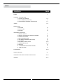
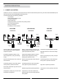
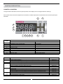
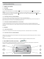
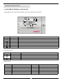
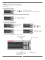
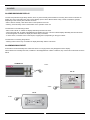
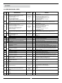
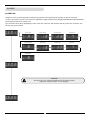
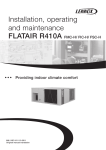
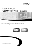
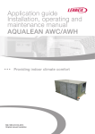
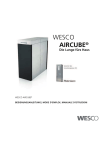
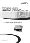
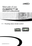
User manual CLIMATIC™ 40 Providing indoor climate comfort MUL37E-0607 07-2007 INDEX CONTENTS PAGE • INDEX 1 • CONTROL DESCRIPTION 1.- CLIMATIC 40 CONTROL 2.- DC41 TERMINAL (ECOLEAN) 3.- DC40 REMOTE TERMINAL (AIRCOOLAIR) 2-4 4 5-7 • MENU 8-9 • REGULATION 1.- ECOLEAN 2.- AIRCOOLAIR 3.- AIRCUBE 10 10 10 • ADVANCED FUNCTIONS 1.- REMOTE ON/OFF 2.- REMOTE CHANGEOVER WINTER / SUMMER 3.- DYNAMIC SET POINT 4.- BMS COMUNICATIONS 5.- TIME BANDS PROGRAM (ECOLEAN) 6.- LOW NOISE 7.- ANALOGIC / DIGITAL INPUT 8.- TIMING AND DELAYS 9.- DEFROST 10.- CONDENSER FAN SPEED CONTROL 11.- FREE COOLING 11 11 11 12 12 13 13-14 14-15 15 16 17 • PARAMETERS 18-20 • SAFETY DEVICES 21 • ASSEMBLY AND INSTALLATION INSTRUCTIONS 22-23 • ALARMS 24-27 CONTROL DESCRIPTION 1.- CLIMATIC 40 CONTROL Climatic 40 control, is an electronic device that controls Ecolean units EAC/EAR (chiller units), Aircoolair units ANCM/ANHM (air-air units) and Aircube units KSCM/KSHM (condensing units). The thermostat allows the following operations: • Unit ON/OFF. • Select system operating mode. • Set point adjustment. • Alarm signal relay. • Display temperature, units status and pending alarms. • Time bands programming. • BMS comunications. • Possibility of remote ON/OFF. ECOLEAN AIRCOOLAIR AIRCUBE EAC/EAR-SM ANCM/ANHM KSCM/KSHM Expansión board Outlet water temperature Return or remote ambient temperature BM40 Fan speed control Evaporator temperature DC 41 Inlet and outlet water, temperature/pressure condenser and outdoor (optional) temperature probes. Proportional regulation based on inlet water temperature (cooling and heating mode). Condenser temperature /pressure BM40 Outside temperature (optional) PWM Outside temperature (optional) Retur air duct temperature BM40 PWM Inlet water temperature PWM Condenser temperature /pressure Expansión board Expansión board DC 40 Fan speed control Free cooling motor damper Fan speed control Return / remote ambient, evaporator, tem- Condenser temperature/pressure probes. perature/pressure condenser and outdoor (optional) temperature probes. Regulation based on remote free voltage contacts. Proportional regulation based on remote ambient /return temperature (cooling, Defrost cycle (heat pump units), with presheating and automatic mode). sure tranducer. Defrost cycle (heat pump units), with pres- Defrost cycle (heat pump units), with pres- Condensing pressure control with tempesure tranducer. sure tranducer. rature probe or pressure transducer. Condensing pressure control with temperature probe or pressure transducer. Condensing pressure control with temperature probe or pressure transducer. Flow switch, antifreeze, high and low pressure protections. Antifreeze, high and low pressure protections. Compressors, water pump, fans and electrical heater management. Compressors, indoor and outdoor fans, electrical heater and freecooling (optional) management. High and low pressure protections. Compressors, indoor (optional) and outdoor fans. CONTROL DESCRIPTION CLIMATIC 40 CONTROL The figure and the table below, show the symbols present on the display and on the keypad and their meanings: Main screeen shows: inlet water temperature for ECOLEAN, ambient temperature for AIRCOOLAIR and unit status (On/Off) for AIRCUBE. I J L K H G F E D C B A SYMBOL 1:02 3:04 A B C D E F G H DESCRIPTION LED ON LED FLASHING Compressor 1 and /or 2 (circuit 1) ON. Compressor 3 and /or 4 (circuit 2) ON. At least 1 compressor ON. Water pump/Indoor fan ON. Condenser fan ON. Defrost active. Electrical heater ON. Alarm active. Cooling mode. Heat pump mode. Start up request. Start up request. Start up request. Start up request. Cooling mode request. Heat pump mode. Request. BUTTON DESCRIPTION TIME I Go up a sub-group inside the programming area, until exiting (saving changes to EEPROM). Access the direct parameters. Select item inside the programming area and display value of direct parameters/confirm the changes to the parameters. Program parameters afters entering password. Select top item inside the programming area. Increase value. Switch from standby to heat pump mode and vice versa. Provides immediate access to the condenser and evaporator pressure and temperature probes. Select bottom item inside the programming area. Decrease value. Switch from stand-by to chiller mode and vice versa. Provides immediate access to the condenser and evaporator pressure and temperature probes. Manual alarm reset. Immediately reset the hour counter (inside the programming area). Force manual defrost on both circuits. Press once Press for 5 s Press once Press for 5 s Press once Press once Press for 5 s Press once Press once Press once Press for 5 s Press once Press for 5 s Press for 5 s Press for 5 s L I+L J K J+K L+J CONTROL DESCRIPTION 1.- CLIMATIC 40 CONTROL 1.1.- ECOLEAN 1.1.1.- TURN ON/OFF THE UNIT In order to turn on the unit, press for 2 seconds the “ ” button, for the heat pump mode, or the “ ” button, for the cooling mode. The display shows unit’s operating mode together with the symbols of the working elements (compressors, water pump etc.). In order to turn off the unit, press for 2 seconds the “ ” button (if the unit is working in heat pump mode) or the “ ” button (if the unit is working in the cooling mode). 1.1.2.- SELECTING THE UNIT´S OPERATING MODE If the unit is in stand-by, the operating mode is selected in the start-up (as explained above). In the case the unit is working in cooling or heating mode, in order to change the operating mode, you have to turn off the unit before, and only then you can turn it on in the operating mode you want. 1.1.3.- SELECTING THE WATER TEMPERATURE OF THE SYSTEM To modify unit working set point you have to change r1 parameter (cooling set point) or r3 parameter (heating set point). To see how to change a parameter see chapter 3 MENU (SETPOINT SETTINGS AND OPERATING HOURS DISPLAY MENU paragraph). 1.2.- AIRCUBE 1.2.1.- TURN ON/OFF THE UNIT The unit turns on closing On/Off contact and turns off opening it (see section 1, advanced functions, for more details). 1.2.2.- SELECTING THE UNIT´S OPERATING MODE Heating mode is selected opening remote changeover contact while cooling mode is selected closing it (see section 2, advanced functions, for more details). NOTE Set point has no meaning in Aircube units because the compressors are directly controlled by remote contacts. 2.- DC41 REMOTE CONTROL (ECOLEAN) OPTION DC41 terminal is an optional keypad that allows to manage Climatic 40 controller from a remote position. The buttons and indications on the display faithfully reproduce the Climatic 40 user interface. J+K J I+L L I K CONTROL DESCRIPTION 3.- DC40 REMOTE TERMINAL (AIRCOOLAIR) The figure and the table below, show the symbols present on the display and on the keypad and their meanings. In the main field of display, it appears OFF, if the machine is stopped or the set point, if the machine is working. 1 2 3 4 11 10 9 8 7 BUTTON 6 5 NAME POWER MODE Mode FAN DESCRIPTION Switch from stand-by to ON and vice versa. Change operating mode (cooling, heating, automatic). Switch the indoor fan from automatic mode to always ON and vice versa. SLEEP Activate/deactivate the sleep mode. CLOCK Activate/deactivate the time bands. TEMP. Show the setpoint when the unit is OFF. UP/DOWN Set the temperature set point. Secundary functions: BUTTON BUTTON PRESS FUNCTION 3 seconds Set sleep differential value of the current operating mode. 3 seconds Set the time bands (hour, day, set point). 5 seconds Clock setting. 3 seconds Reset alarms. Display symbols: SYMBOL MEANING SYMBOL MEANING 1 Heating mode. 7 On/Off time bands. 2 Cooling mode. 8 Sleep mode. 3 Automatic mode. 9 Sleep mode duration. 4 Set point. 10 Alarm. 5 Day of the week (weekday, weekend). 11 Indoor fan mode. 6 Hour/Temperature. CONTROL DESCRIPTION 3.1.- TURN ON/OFF THE UNIT WITH REMOTE CONTROL DC40 (AIRCOOLAIR) To turn on the unit press the “ ” button. The display shows current operating mode. 3.2.- SELECTING THE UNIT´S OPERATING MODE Once the unit is turned on, you can select Cooling, Heating or Automatic mode just pressing “Mode” button. In the automatic mode you just choose the set point and the system automatically switches from cooling to heating mode, depending on the position of the ambient temperature in respect to the set-point. 3.3.- SELECTING DESIRED ROOM TEMPERATURE If unit is working, the “ ” buttons allow to select the desired room temperature (set-point). The button “↑” allows the increase of the current set-point by 0.5ºC. The button “↓” allows the decrease of the current set-point by 0.5ºC. 3.4.- SELECTING THE FAN OPERATING MODE (Aircoolair) To be able to select a fan operating mode, cool, heat or auto unit’s operating mode must be selected. Pressing “ ” side button scrolls through the following modes: FAN CONSTANTLY ON, or AUTO FAN CONSTANTLY ON: Fan is continuous ON, the symbol “ ” will appear. AUTO: Fan on and off together with the compressor, the symbol “ ” will appear. 3.5.- SLEEP FUNCTION This function increases (in cooling mode) or decreases (in heating mode) the operating set point according to the lower level of comfort required during the night. Not possible with time bands program. ACTIVATION Press once “ ” button. The display shows “ ” symbol with “1HR” flashing. In this way, sleep function will be working for 1 hour. If you want it works for more hours, press “ ” button more times while “1HR” is still flashing (each button pression increases by 1 hour, till max 9 hours). At the end the display shows “ ” symbol with the number of hours you choose. DEACTIVATION Press once “ ” button and sleep function will be deactivate (if it was activated before). Symbol “ ” disappears from the display. DIFFERENTIAL SETTINGS Press “ ” button for 3 seconds. Sleep differential (the value you increase or decrease to comfort set-point) appears on the display. Use “ ” buttons to set the value, then press “ ” button to accept. Note that cooling and heating mode have different sleep differential values, so you can modify only current operating mode’s one. 3.6.- CLOCK SETTINGS To set actual time: 1. Press “ ” button for 6 seconds. “rtc” and actual time appears on the display (hours are flashing). 2. Set the hour by “ ” buttons. 3. Press “ ” button to accept. Minutes start flashing on the display. 4. Set the minutes by “ ” buttons. 5. Press “ ” button to accept. “day” and the number of the day of the week appear on the display (Monday=1, Tuesday=2 etc.) 6. Set the day by “ ” buttons. 7. Press “ ” button to accept. 3.7.- TIME BANDS PROGRAM This function allows you to program time bands during the week, each one with a different set-point. In this way you can suit the cool/heat provided by the unit to each moment of the day. You can set two time bands for the weekdays and other two for the weekend. CONTROL DESCRIPTION CONFIGURATION a) Enter time bands menu. b) Set 1 ST time band of weekdays starting hour. c) Accept. Weekdays Time band 1 3 sec. flashing d) Set 1ST time band of weekdays starting minutes. e) Accept. f) Set 1ST time band of weekdays set-point (on/off/temperature). Flashing g) Accept. Flashing h) Repeat b-c-d-e-f-g steps to program 2sd time band of weekdays. i) Repeat b-c-d-e-f-g-h steps to program the two time bands of weekend. Weekend Flashing Time band 2 Hashing ACTIVATION EXAMPLE IN SUMMER DEACTIVATION Hour Weekdays Weekend 8:00 (Time band 1) 22ºC 23ºC OFF 18:00 (Time band 2) NOTA: You must set the DC40 clock before programming time bands. OFF MENU Access to the menu: A) PROBES DISPLAY MENU 1 sec. Press “ ” button, to enter probes display menu. “ b01” or “b02”, appears on the display (it depends on the unit configuration). B) SETPOINT SETTINGS AND OPERATING HOURS DISPLAY MENU Press “ Sel ” button, for 5 seconds. “ ”, appears on the display. 5 sec. C) PARAMETERS EDITING MENU 5 sec. a) Press “ Pgr ” and “ Sel”, at the same time, for 5 seconds. b) Set password “ 22 ” by “ ” and “ ” buttons. d) Press “ Sel ”, to enter parameters Editing menu. c) Press “ Sel ”, to accept. To go to different values in the menu, follow the previous information. Go up a sub-group inside the programming area. Go down a sub-group or accept parameter modifications inside the programming area. UP or increase valve. Down or decrease valve. MENU MENU TREE PROBES SETTINGS ATIFREEZE AND ELECTRICAL HEATER PROBES COMPRESSORS DEFROST FANS UNIT SETTING ALARMS REGULATION TIMER SETTING SOFTWARE NOTES: a) The parameters that have been modified without being confirmed using the “ Sel ” button, return to the previous value. b) If no operations are performed on the keypad for 60 seconds, the controller exits the parameter editing menu by timeout and the changes are cancelled. REGULATION 1.- ECOLEAN Inlet water temperature is thermostatically controlled via set point and tolerance range (differential) as shown in the following diagrams: 1.1- COOLING OPERATING MODE 1.2- HEATING OPERATING MODE STEP 1 STEP 2 Inlet water temperature (ºC) r2 r1 STEP 2 STEP 1 Inlet water temperature (ºC) r4 Unit 2 CM r3 Unit. 2 CM 1.3- AFFECTED PARAMETERS Par. r1 r2 r3 r4 VALVE UNIT 1CM. DESCRIPTION Cooling set point Cooling differential. Heating set point. Heating differential VALVE UNIT 2CM. VALVE UNIT 3CM. VALVE UNIT 4CM. MIN. MAX. DEF. MIN. MAX. DEF. MIN. MAX. DEF. MIN. MAX. DEF. 10 0.3 20 0.3 22 50 43 50 11 2 41 2 9 0.3 20 0.3 22 50 43 50 10 3 42 3 8 0.3 20 0.3 22 50 43 50 9 4 43 4 8 0.3 20 0.3 22 50 43 50 9 4 43 4 2.- AIRCOOLAIR Ambient (or return air duct) temperature is thermostatically controlled via set point and tolerance range (differential) as shown in the following diagrams: 2.1- AUTOMATIC MODE (Heat pump) HEAT 2.2- AUTOMATIC MODE (Cooling only+Electrical heater) COOL HEAT EH2 CM2 BE2 CM2 CM1 r4 r7 r2 CM2 BE1 EH1 CM1 r7 COOL A9 Ambient temperature (ºC) CM1 A9 r7 A8 r2 Ambient temperature (ºC) A11 SP SP 2.3- AFFECTED PARAMETERS Par. SP r2 r4 r7 A8 A9 A11 DESCRIPTION Set point (DC40). Cooling differential. Heating differential. Dead zone. SP E.H. 1 cool / SP E.H. 1 heat Differential E.H. SP E.H. 2 cool. UNIT 2 COMPRESSORS UNIT 3 COMPRESSORS MIN. UNIT 1 COMPRESSOR MAX. DEF. MIN. MAX. DEF. MIN. MAX. DEF. 8 0.3 0.3 0.3 0 0.3 0 32 50 50 50 20 50 20 23 1 1 0.5 1.5/2.5 1 2.5 8 0.3 0.3 0.3 0 0.3 0 32 50 50 50 20 50 20 23 2 2 0.5 1.5/3.5 1 2.5 8 0.3 0.3 0.3 0 0.3 0 32 50 50 50 20 50 20 23 4 4 0.5 1.5/4.5 1 2.5 3.- AIRCUBE Aircube´s regulation is performed by digital inputs. (see section 7, advanced functions, for more details). 10 ADVANCED FUNCTIONS 1.- REMOTE ON/OFF This function allows you to turn on/turn off the unit by a simply remote contact (contacts 95-96). Close contact = ON; Open contact = OFF. 2.- REMOTE CHANGEOVER WINTER/SUMMER On heat pump units (also in Aircoolair cooling only + electrical heater), it is possible to select cooling or heating mode by a remote contact (contacts 97-98). Close contact = Cooling.; Open contact = Heating. To activate this function set parameter H06=1. WARNING In Aircoolair units, if the automatic mode has been selected by DC40, remote changeover doesn’t work. OPTION 3.- DYNAMIC SET POINT With this function, which needs to incorporate an additional outdoor temperature probe, it’s possible to have a dynamic adjustment to the set point based on ambient temperature. The set point value can be increased or decreased when the external conditions are more advantageous, so an extra energy saving can be achieved. Dynamic setpoint must be activated in the factory. User must set the parameters as shown in the graphics below: ECOLEAN Set point ºC COOL r1 Set point ºC HEAT r18 r18 r3 Temp. ext. ºC r19 r20 SP = r1 + (T.ext. - r19) x r17 SP = r3 + (T.ext. - r20) x r31 EXAMPLE EXAMPLE SP 14ºC 11ºC 25ºC 35ºC r1 = 14ºC r3 = 38ºC r17 = -0.3 r18 = 3ºC r18 = 3ºC r20 = 12ºC r19 = 25ºC r31 = -0.5 Temp. ext. ºC SP 41ºC 38ºC Temp. ext. ºC 6ºC 12ºC Temp. ext. ºC AIRCOOAIR Set point ºC COOL Set point ºC HEAT SP (DC40) r18 r18 SP (DC40) r19 Temp. ext. ºC SP = SP(DC40) + (T.ext. - r20) x r31 EXAMPLE EXAMPLE SP 26ºC 24ºC 35ºC 45ºC Temp. ext. ºC r20 SP = SP(DC40) + (T.ext. - r19) x r17 SP (DC40) = 24ºC SP SP (DC40) = 21ºC r17 = 0.2 r18 = 2ºC r18 = 2ºC r20 = 6ºC r19 = 35ºC r31 = 0.2 Temp. ext. ºC 21ºC 19ºC -4ºC 11 6ºC Temp. ext. ºC ADVANCED FUNCTIONS OPTION 4.- BMS COMMUNICATIONS Since the unstoppable growing trend of Building Automation, driven by the powerful ever evolving connectivity, controller climatic 40 offers the possibility to communicate to Building Management Systems (BMS) via Modbus protocol. Modbus standard interface is integrated in the control, so you don’t need any sort of gateway, router, etc. In order you to connect to RS485 serial line we provide, as optional, TTL-RS485 converter for Ecolean and Aircube units. Aircoolair units don’t need the converter (it’s integrated) but they need ambient or duct remote sensor option. MODBUS ECOLEAN AIRCOOLAIR For further information, please see BMS communiction manual. 5.- TIME BANDS PROGRAM (Ecolean) Controller Climatic 40 allows to program 2 time bands every day, each one with a different set point. Settings parameters are explained in the following table: COOLING 1st TIME BAND HEATING TIME SET POINT TIME SET POINT Rest of the day r1 Rest of the day r3 (hour:minutes) t06:t07 Start 2nd TIME BAND End (hour:minutes) t12:t13 r21 (hour:minutes) t08:t09 End Start (hour:minutes) t10:t11 r22 EXAMPLE (Cooling): HOUR Monday Tuesday Wednesday Thursday Friday Saturday Sunday 8:00-18:00 11ºC 11ºC 11ºC 11ºC 11ºC 11ºC 11ºC 18:00-8:00 (t06:t07-t08-t09) 16ºC 16ºC 16ºC 16ºC 16ºC 16ºC 16ºC WARNING Set internal clock before programming time bands (t01=hour, t02=minutes, t03=day, t04=month, t05=year). To deactivate time bands program, set start time = end time. 12 ADVANCED FUNCTIONS 6.- LOW NOISE This function is available only in the following units: ECOLEAN EAC + kit -15ºC y EAR 251-812 SM AIRCOOLAIR ANCM + kit -15ºC y ANHM 22E-86D AIRCUBE KSCM + kit -15ºC y KSHM 22E-86D This function moves the condensing pressure set point so as to lower the fan speed and consequently reduce noise (specifically at night). If low noise is active in cooling, the condenser control set points are increased by 5º bar. If low noise is active in heating, the set points are reduced by 1º bar. Set F15=3 to active this function. Furthermore set the following parameters: COOLING HEATING TIME FAN TIME FAN Rest of day Standard Rest of day Standard Start (hour:minutes) t14:t15 End (hour:minutes) t16:t17 LOW NOISE Start (hour:minutes) t18:t19 End (hour:minutes) t20:t21 LOW NOISE Low noise cooling mode shift is illustrated in the following picture. SPEED FAN 100% 40% 0% CONDENSER PRESSURE (bar) 18 18.5 20 23 23.5 25 26 31 7.- ANALOGIC / DIGITAL INPUT PROBES TABLE PROBE DC40 b1 b2 ECOLEAN EAC Inlet water temperature Outlet water temperature b3* 1st Circuit condenser temperature b4 Outlet temperature ** b6 AIRCOOLAIR EAR Temperatura exterior ** 1st Circuit condenser temperature Temperatura exterior ** AIRCUBE KSCM 2st Circuit condenser temperature 2st Circuit condenser pressure 1st Circuit condenser pressure 2st Circuit condenser temperature 2st Circuit condenser pressure * Except: EAC 1003-1103-1303-1403-1604-1804-2104 SM ANCM 112D-128D-152D. KSCM 112D-128D-152D-214D ** Optional elements. NOTE: Optional kit could change probes settings. 13 KSHM 1st Circuit condenser temperature st 1st Circuit condenser condenser Outlet temperature ** 1 Circuit pressure pressure 2st Circuit evaporator temperature b7* b8 ANCM ANHM Ambient temperature Return or remote ambient temperature ** 1st Circuit evaporator temperature 2st Circuit condenser pressure ADVANCED FUNCTIONS DIGITAL INPUT TABLE ECOLEAN DIGITAL INPUT EAC ID1 AIRCOOLAIR EAR ANCM Flow switch ID2 AIRCUBE ANHM Cool/Heat Cool/Heat ID3 ID4 Low pressure circuit 1 ON/OFF KSHM ON/OFF Cool/Heat High pressure circuit 1 ID5 KSCM Termal overload fan Cool/Heat ON/OFF Step 1 ID6 Step 3 ID7 Step 2 ID8 High pressure circuit 2 ID9 Low pressure circuit 2 ID10 Step 4 8.- TIMING AND DELAYS COMPRESSOR In order to protect compressors from destructively cycling on and off, following protection delays have been set: unit ON ON CM2 ON ON CM1 120 5 300 2 Time (sec.) COMPRESSOR- WATER PUMP (ECOLEAN) In both heating and cooling modes, the compressors start 150 seconds after the water pump has started in order to stabilize the water system. In addition to that, the water pump stops 4 minutes later than last compressor has stopped, in order to take advantage of the remaining thermal energy in the exchanger. 150 s. 240 s. Compressor ON Water pump ON 14 ADVANCED FUNCTIONS WATER PUMP- WATER FLOW SWITCH (ECOLEAN) Water flow switch assures that water pump does not work when there is no water flow. There is a by-pass during the first 150 seconds of water pump operation because of water flow switch signal. When the alarm has been activated, water pump is stopped. Water pump starts again every 90 seconds during a time of 150 seconds, to try to reset the alarm. This procedure is repeated 5 times and after that the pump remains stopped until the alarm does not reset manually. ALARM flow open close PUMP 150” 5” 90” 150” 90” 150” 9.- DEFROST The defrosting process is activated during heating mode in heat pump units, when the outside temperature is low and the outdoor coil could become frozen. To melt the ice the defrosting function will switch the unit to cooling operation for a short period. During defrosting mode the low pressure is at minimum level, consequently the pressure switch is disabled in this mode. Defrost cycle is illustrated in the following picture. 20 Condenser pressure (bar) 5.7 60” Compressors HEAT COOL 60” COOL 60” Reverse valve 30” 30” If the pressure does not reach the 20 bars before 8 minutes from the beginning of defrost cycle, the cycle finishes because of maximum time and in the display appears “dF1” or “dF2” (according to the circuit). Time between two defrost cycles for the same circuit: 40 minutes. Time between two defrost cycles of both circuits: 10 minutes. 15 ADVANCED FUNCTIONS 10.- CONDENSER FAN SPEED CONTROL The function of the fan speed control is to prevent very low condensing temperatures during cooling mode operation between 0ºC and 46ºC outside temperatures. Depending on the unit, this function could be: 1.1.- PROPORTIONAL CONTROL BASED ON PRESSURE Models: ECOLEAN: EAC + kit -15ºC and EAR 251-812 SM AIRCOOLAIR: ANCM + kit -15ºC and ANHM 22E-86D AIRCUBE: KSCM + kit -15ºC and KSHM 22E-86D In this case, it is a proportional fan speed control, which varies the fan voltage supplied to the fan. FAN SPEED 100% NOTE At start-up the fan works at maximum speed for 20 seconds, so as to overcome the mechanical inertia of the motor. 40% 0% 18 18.5 20 CONDENSER PRESSURE (bar) 26 1.2.- PROPORTIONAL CONTROL BASED ON PRESSURE TEMPERATURE Models: ECOLEAN: EAC 251-812 SM AIRCOOLAIR: ANCM 22E-86D AIRCUBE: KSCM 22E-86D In this case too, it is a proportional fan speed control, which varies the fan voltage supplied to the fan. FAN SPEED NOTA At start-up the fan works at maximum speed for 20 seconds, so as to overcome the mechanical inertia of the motor. The same time is observed in reference to the start of the compressor (irrespective of the condensing temperature) in order to bring forward the sudden increase in pressure (which does not necessarily correspond to a likewise rapid increase in temperature in the area where the probe is located) and consequently to improve control. 100% 40% 0% 18 19 28 40 CONDENSER TEMPERATURE (ºC) 1.3.- ON/OFF CONTROL BASED ON PRESSURE Models: ECOLEAN: EAR 1003-2104 SM AIRCOOLAIR: ANHM 112D-152D AIRCUBE: KSHM 112D-214D ON/OFF, through the control and change between high and low fan speed through pressure switches. The fans for these models incorporate 2 speeds. The fans work on high or low speed according to: COOLING MODE: The on/off and low/high fan speed is managed according to the condensing pressure. See the drawing below: HEATING MODE (only heat pump units). The low/high fan speed is managed according to the ambient thermostat. See the drawing below: COOLING MODE High speed High speed Low speed Low speed 0ºC 22 bar 15ºC 30ºC 35ºC 28 bar 30 bar 37 bar Outside temperature ºC Condensing pressure 16 HEATING MODE +7ºC Outside temperature ºC ADVANCED FUNCTIONS OPTION 11.- FREE COOLING This option takes advantage of external conditions for cooling mode. The freecooling is enabled when outdoor temperature is 1ºC lower than indoor temperature and when the first one is: - < 10ºC, deactivate compressors and open completely air intake gate in order to refresh only by outdoor air (enough in this conditions). - >10ºC, open air intake gate and delay compressors, which turn on only in the case outdoor fresh air would not be sufficient to achieve comfort setpoint. Picture below shows freecooling regulation. CM3 SP Without free cooling CM2 CM1 Ambient temperature (ºC) 23 23.5 25 R02/4 With free cooling Open air damper. Close air damper. Stop air damper. 23 23.5 24 24.5 Ambient temperature (ºC) 26 To get a constant air renovation, the damper can be partially open, according to the following values. Par. DESCRIPTION Min. Max. Def. 0 9 0 0 100 0 It indicates when to carry out the minimum opening of the damper. 0= Never. 1= with freecooling. 2= with freeheating. 3= with freecooling and freeheating r40 4= always, except with freecooling y freeheating. 5= always, except with freeheating. 6= always, except with freecooling. 7= always 8= only for cooling mode. 9= only for heating mode. r41 % minimum percentage opening damper. 17 PARAMETERS DESCRIPTION PAR. MIN. MAX. VAR. UD. ECOLEAN Antifreeze and electrical heater BY DEFAULT AIRCOOLAIR AIRCUBE ------ A01 Antifreeze alarm set point. A7 A4 0.1 ºC 3,0 2 A02 Antifreeze differential. 0,3 122 0.1 ºC 5,0 5 ------ 0 150 1 sec. 0 30 ------ A04 Antifreeze heater set point. A1 R16 0.1 ºC 4,5 ------ ------ A05 Antifreeze heater differential. 0,3 50 0.1 ºC 1,0 ------ ------ A1 R16 0.1 ºC 35 ------ ------ A03 By-pass time for antifreeze alarm. Auxiliary heater absolute set point (1st step). 1.5 (ANCM) A08 Auxiliary heater relative set point (1 step). st 2.5 (ANHM 22E-43E) 0 20 0.1 ºC ------ 0 20 0.1 ºC 1 1 ------ A1 R16 0.1 ºC 33 ------ ------ 3.5 (ANHM 52D-86D) ------ 4.5 (ANHM 112D-152D) A9 Auxiliary heater differential. A11 Auxiliary heater absolute set point (2st step). Auxiliary heater relative set point (1st step). 0 20 0.1 ºC ------ 2.5 (ANCM 52D-86D) ------ A13 Lower discharge air temperature in freecooling. A7 R16 0.1 ºC ------ 7 ------ 0 11 10 Probes Config. of probe to be shown on the display: b0 0= probe B1. 1= probe B2 2= probe B3. 3= probe B4 4= probe B5. 5= probe B6 6= probe B7. 7= probe B8 0 11 1 N b1 Probe B1. ------ b2 Probe B2. ------ ------ ------ ºC ------ ------ b3 Probe B3. ºC ------ ------ ------ ºC b4 Probe B4 ------ ------ ------ ºC/bar b5 Probe B5. ------ ------ ------ ºC b6 Probe B6. ------ ------ ------ ºC ºC 8= Set point without cmpensation. 9= Dynamic set point with possible compensation. 10= Remote ON/OFF digital input status. 11= Terminal DC40 probe. b7 Probe B7. ------ ------ ------ b8 Probe B8. ------ ------ ------ ºC/bar b21 Probe DC40. ------ ------ ------ ºC Timming and delays C01 Min. compressor ON time. 0 999 1 sec. 0 0 0 C02 Min. compressor OFF time. 0 999 1 sec. 120 120 120 300 C03 Delay between 2 starts of the same compressor. 0 999 1 sec. 300 300 C04 Delay between starts of the 2 compressor. 0 999 1 sec. 2 2 2 C05 Delay between 2 shut-downs of the 2 compressors. 0 999 1 sec. 0 0 0 C06 Delay at start up. C07 Delay in switching on the compressor after switching on the pump. 0 999 1 sec. 5 5 5 0 999 1 sec. 150 0 0 4 0 0 0 0 0 C08 Delay in switching off the compressor after switching off the pump. 0 150 1 min. C10 Compressor 1 timer. 0 8000 100 hours hours C11 Compressor 2 timer. 0 8000 100 C12 Compressor 3 timer. 0 8000 100 hours C13 Compressor 4 timer. 0 8000 100 hours C14 Operation timer threshold (0=not used). 0 100 100 hours C15 Hour counter evaporator pump. 0 8000 100 hours C17 Minimum time between 2 pump starts. 0 150 1 min. 0 0 0 C18 Minimum pump/indoor fan ON time. 0 150 1 min. 0 1 0 18 PARAMETERS DESCRIPTION PAR. MIN. MAX. VAR. UD. ECOLEAN BY DEFAULT AIRCOOLAIR AIRCUBE Defrost d01 Defrosting cycle activation. 0 1 1 flag 1 1 1 d03 Start defrosting pressure. 1 D04 0.1 bar 5.7 5.7 5.7 d04 End defrosting pressure. D03 /12 0.1 bar 25 25 25 10 150 1 sec. 60 60 60 d06 Min. duration of a defrosting cycle. 0 150 1 sec. 0 0 0 d07 Max. duration of a defrosting cycle. 1 150 1 min. 8 8 8 d08 Delay between 2 defrosting cycle requests with in the same circuit. 10 150 1 min. 40 40 40 d09 Defrosting delay between the 2 circuits. 0 150 1 min. 10 10 10 d05 Min. time to start a defrosting cycle. Fan Fan operating mode: 0= Always ON. F02 1= Depending ON compressor (in parallel operating mode). 0 3 1 int. 2= Depending ON compressors in ON/OFF control. 1 (EAC 1003-2104) 1 (ANCM 112D-152D) 1 (KSCM 112D-214D) 2 (EAR 1003-2104) 2 (ANHM 112D-152D) 2 (KSHM 112D-214D) 3 (EAC/EAR 251-812) 3 (ANCM/HM 22E-86D) 3 (KSCM/HM 22E-86D) 28 28 28 3= Depending ON compressors in speed control mode. F05 F06 F07 F08 F09 Temp. value for min. speed cooling. -40 176 0.1 ºC Pressure value for min. speed cooling. /11 /12 0.1 bar 20 (if F2=3) / 22 (if F2=2) 20 (if F2=3) / 22 (if F2=2) 20 (if F2=3) / 22 (if F2=2) Differential value for max. speed in cooling mode (temp). 0 50 0.1 ºC 12 12 Differential value for max. speed in cooling mode (pres). 0 30 0.1 bar 6 6 6 Fan shut-down differential in cooling mode (temp). 0 50 0.1 ºC 10 10 10 Fan shut-down differential in cooling mode (pres). 12 0 F5 0.1 bar 2 2 2 Temperature value for min. speed in heating mode. -40 176 0.1 ºC 30 30 30 Pressure value for min speed cooling. 12 (if F3=3) / 22 (if F3=2) 12 (if F3=3) / 22 (if F3=2) 12 (if F3=3) / 22 (if F3=2) /11 /12 0.1 bar Differential value for max. speed in heating mode (temp). 0 50 0.1 ºC 1 1 1 Differential value for max. speed in heating mode (pres). 0 30 0.1 bar 5 5 5 Fan shut-down differential in heating mode (temp). 0 50 0.1 ºC 0 0 0 Fan shut-down differential in heating mode (pres). 0 F8 0.1 bar 13 13 13 0 120 1 20 20 20 0 3 1 flag 0 0 0 F16 Differential Low Noise in cooling mode. 0 50 0.1 bar 5 5 5 F17 Differential Low Noise in heating mode. 0 50 0.1 bar 1 1 1 F10 F11 Fan starting time. Activation Low Noise: 0= Deactivate. F15 1= Activate only in cooling mode. 2= Activate only in heating mode. 3= Activate both in cooling and heating mode. Setting Activate remote change over: H06 0= Deactivate. 0 1 1 flag 0 0 0 (KSCM) 1 (KSHM) 0 1 1 flag 1 1 1 H10 Serial address. 1 200 1 ud. 1 1 1 H23 Activate Modbus. 0 1 1 flag 0 0 0 1 1 1 1= Activate. ON/OFF remoto: H07 0= Deactivate. 1= Activate. H97 Expansion board software version. 0 999 1 flag H99 Software version. 0 999 1 flag Alarms Enable part load in high pressure: 0= Capacity control deactivated. P04 1= Capacity control activated for high pressure. 0 3 1 flag 2= Capacity control activated for low pressure. 3= Capacity control activated for high and low pres. 19 PARAMETERS PAR. DESCRIPTION MIN. MAX. VAR. UD. Regulación ECOLEAN BY DEFAULT AIRCOOLAIR AIRCUBE 24 ------ 11 (EAC/EAR 251-431) r1 Cooling set point. R13 R14 0.1 ºC 10 (EAC/EAR 472-812) 9 (EAC/EAR 1003-2104) r2 Differential in cooling mode. 0.3 50 0.1 ºC 2 (EAC/EAR 251-431) 1 (ANCM/HM 22E-43E) 3 (EAC/EAR 472-812) 2 (ANCM/HM 52D-86D) ------ 4 (EAC/EAR 1003-2104) 4 (ANCM/HM 112D-152D) 41 (EAC/EAR 251-431) r3 Heating set point. R15 R16 0.1 ºC 42 (EAC/EAR 472-812) 22 ------ 43 (EAC/EAR 1003-2104) r4 Differential in heating mode. 0.3 r7 Dead zone. r17 Cooling compensation constant. r18 Maximum distance from the set point. 1 50 0.1 -5 5 0.1 r19 Start compensation temerature in cooling mode. r20 Start compensation temerature in heating mode. r21 Second cooling set point. r22 Second heating set point. r23 Select automatic change over probe. r24 Automatic change over set point. r25 Outside temp. set point to stop compressors. r31 Heating compensation constant. 50 0.1 2 (EAC/EAR 251-431) 1 (ACHM 22E-43E) 3 (EAC/EAR 472-812) 2 (ANHM 52D-86D) 4 (EAC/EAR 1003-2104) 4 (ANHM 112D-152D) ºC ------ 0.5 ------ ------ 0 0 ----------- ºC ------ 0.3 20 0.1 ºC 3 2 -40 176 0.1 ºC 25 35 ------ -40 176 0.1 ºC 12 6 ------ R13 R14 0.1 ºC 16 28 ------ R15 R16 0.1 ºC 35 18 ------ 0 8 1 flag 0 0 ------ R15 R16 0.1 ºC ------ 23 ------ -40 80 0.1 ºC -15 -15 -15 -5 5 0.1 ------ 0 0 0 Reloj t01 RTC hours. t02 RTC minutes. t03 RTC days. t04 RTC month. t05 RTC years. t06 Start hours for 2nd set point in cooling. t07 Start mimutes for 2nd set point in cooling. t08 End hours for 2nd set point in cooling. t09 End minutes for 2nd set point in cooling. t10 Start hours for 2nd set point in heating. t11 Start mimutes for 2nd set point in heating. t12 End hours for 2nd set point in heating. t13 End minutes for 2nd set point in heating. t14 Start hours for 2nd low noise cooling. t15 Start mimutes for 2nd low noise in cooling. t16 End hours for 2nd low noise in cooling. 0 23 1 ------ 0 59 1 ------ 1 31 1 ------ 1 12 1 ----------- 0 99 1 0 23 1 ------ 0 0 0 0 59 1 ------ 0 0 0 0 0 23 1 ------ 0 0 0 59 1 ------ 0 0 0 0 23 1 ------ 0 0 0 0 59 1 ------ 0 0 0 0 23 1 ------ 0 0 0 0 59 1 ------ 0 0 0 0 23 1 ------ 0 0 0 0 59 1 ------ 0 0 0 0 0 23 1 ------ 0 0 t17 End minutes for 2nd low noise in cooling. t18 Start hours for 2nd low noise in heating. 0 59 1 ------ 0 0 0 0 23 1 ------ 0 0 0 t19 Start mimutes for 2nd low noise in heating. t20 End hours for 2nd low noise in heating. 0 59 1 ------ 0 0 0 0 23 1 ------ 0 0 0 t21 End minutes for 2nd low noise in heating. 0 59 1 ------ 0 0 0 WARNING Default values could change according to the optional kits or improvements. 20 SAFETY DEVICES ANTIFREEZE PROTECTION (ECOLEAN). This protection is activated by the control of the unit when the outlet water temperature probe (b2), located inside the water exchanger, measures +4.5ºC and deactivates when the outlet water temperature probe reaches +5.5ºC again. When the protection is activated occurs as follow: - If the unit operating mode is STAND-BY : the water pump goes on, the same happens to electrical heater of water exchanger and electrical heater of water tank (if included). DO NOT TURN OFF THE POWER TO THE UNIT. WHEN THE POWER IS OFF THE ANTI FREEZE PROTECTION WILL NOT OPERATE. - If the unit is operating on cooling mode: feeds the electrical heater of water tank, the electrical heater of the water exchanger, and activates the hot gas injection valve (if the unit incorporates these options). LOW WATER TEMPERATURE ALARM (ECOLEAN). This alarm activates when the outlet water temperature probe (IS1) measures a value of + 3 ºC in standard unit. Go stop the unit. The alarm could be reset when outlet water temperature reaches + 8ºC in standard unit. NOTE: Low water temperature options change the values of antifreeze protection and low water temperature alarm. ANTIFREEZE PROTECTION (AIRCOOLAIR). The unit self-protects through a temperature probe located in the indoor piping, when this temperature goes down 2ºC happens: CASE WITHOUT FREECOOLING - shut down compressors and antifreeze alarm goes on. - La alarma se rearma automáticamente cuando la temperatura alcance los 7ºC. CASE WITH FREECOOLING - Close air intake gate, - Once the gate is completely closed, shut down compressors and antifreeze alarm goes on. When the air intake gate is closing, if indoor piping temperature goes up 2ºC, the gate stops and keeps the reached position; then, if the temperature achieves 7ºC, the air damper starts opening otherwise, if the temperature goes down 2ºC, the damper start closing again. In addition to that, to prevent frozen air discharge when freecooling without compressors is working (outdoor temp.<10ºC), if indoor piping temperature goes down 7ºC, air intake gate starts to mix outdoor air with return air, increasing discharge air temperature. 21 ASSEMBLY AND INSTALLATION INSTRUCTIONS DC40. Installation instructions 1. Divide the top part of the instrument from the bottom part using a screwdriver as shown in Fig. 8.1. 2. Open the instrument with a “hinge” movement, pivoting the top part of the instrument and lifting the bottom part. Fig. 8.1 Lower view 3. Fix the rear part to the wall, taking care that the connection cables must pass through the hole in the centre of the rear shell. The distances between the fastening holes are designed so as to be able to fit the DC40 to a flush-mounting connection box compliant with the CEI C.431 - IEC 670 standards. If this is not available, use the fastening holes on the shell as a guide for drilling holes in the wall, and then use the kit of screws and plugs supplied. 4. Connect the cables to the terminals located on the shell as indicated in the same shell or in the electrical drawing. Separate cables of the DC41 of inductive loads, cables and power devices (contactors, etc.) in order to prevent electromagnetic interferences. Not include together power and communications cables GND TX+ TX- GO G Fig. 8.2 - Connect from the electrical box in the outdoor unit to DT41 device: . 91 and 92 terminal blocks respectively to Tx+ and Tx -. (Twisted pair of com munications). . 93 and 94 terminal blocks respectively to GO and G. (Twisted pair of power 24VAC). . Borna 90 to GND. (shield). - Type of cable: 2 twisted pairs AWG20 5. Once the installation is finished, fit the terminal on the shell pivoting the top part with a “hinge” movement and close it. When closing, make sure that the pins on the board fit into the corresponding terminals. Installation warnings - Disconnect the power supply before working on the DC40 during the assembly, maintenance and replacement operations. - The terminal must be fastened to the wall so as to allow the circulation of air through the slits on the rear shell. - Avoid installing the boards in environments with the following characteristics: - Avoid locations where the room temperature measurement may be altered. - Near doors leading to the outside. - Outside walls. - Exposure to direct sunlight or to conditioned air flow. - Strong magnetic and/or radio frequency interference (for example, near transmitting antennae). 22 ASSEMBLY AND INSTALLATION INSTRUCTIONS DC41. Installation instructions: 1. Pass the telephone cable through the hole in the rear of the case. 2. Fasten the rear of the case to the box using the round-head screws. 3. Connect the telephone cable to the RJ12 terminal of the DC41. 4. Rest the front panel on the rear of the case and fasten the assembly using the countersunk screws, as shown in Fig. 8.3. 5. Finally, apply the click-on frame. A Fig. 8.3 156.2 Electrical connections: 1. Disconnect the power supply before working on the DC41 during the assembly, maintenance and replacement operations. 2. Make the connection between the power supply “DT41” and the terminal DC41 using the telephone cable (80 cm). supplied. If the cable is not long enough, use a pin-to-pin telephone cable with a maximum length of 10 m. DC41 Fig. 8.4 Separate cables of the DC41 of inductive loads, cables and power devices (contactors, etc.) in order to prevent electromagnetic interferences. Not include together power and communications cables Thelefone cable Max. L=10m. – 92 91 90 + GND RS485 RJ12 – Power supply G G0 24 Vac L. max.=100m. DT41 93 94 - Connect from the electrical box in the outdoor unit to DT41 device: . 91 and 92 terminal blocks respectively to Tx+ and Tx -. (Twisted pair of communications). . 93 and 94 terminal blocks respectively to GO and G. (Twisted pair of power 24VAC). . Borna 90 to GND. (shield). - Type of cable: 2 twisted pairs AWG20 23 ALARMS ALARMS/WARNINGS DISPLAY The unit self-protects through safety devices; when any of these safety devices detect an anomaly, this is shown in Climatic 40 display and, only in Aircoolair units, also in DC41 display (even if with a different alarm code), in order to advise the operator. Depending on the anomaly kind, Climatic 40 shows: • Alarm. Serious anomaly. Have direct effect on the operation of the unit. • Warning. Trivial anomaly. Have no direct effect on the operation of the unit. The activation of an alarm brings about: - Alarm code is shown on Climatic 40 display alternately with the main menu. - Only in Aircoolair units, an alarm code (different from Climatic 40’s one) is shown on DC40 display alternately with the main menu. - A red bell appears on Climatic 40 display and alarm relay is activated. - In some cases, it can block some of the outputs, stopping the unit, depending on the type of alarm. The activation of a warning brings about: - Warning code is shown only on Climatic 40 display alternately with the main menu. ALARM/WARNING RESET Some alarms are automatically reset. When the cause is no longer present, they disappear from the display. Others alarms are manually reset and, in addition to the disappearance of alarm conditions, they need a user-made reset as shown below: CLIMATIC 40 5 Sec. DC 40 3 Sec. DC 41 5 Sec. 24 ALARMS ALARMS/WARNINGS CODES DISP DISP CL40/ DC40 DC41 DESCRIPTION EFFECT High pressure switch alarm, circuit 1. This alarm may indicate the following problems: - High pressure switch protection. - Compressor stopped. - Indoor fan stopped (Aircoolair). - Excessive refrigerant charge. - Insufficient water flow in heating cycle (Ecolean). Circuit 1 compressors stop HP2 High pressure switch alarm, circuit 2. The same as previous alarm but this time referred to circuit 2. Circuit 2 compressors stop LP1 Low pressure switch alarm, circuit 1. This alarm may indicate the following problems: - Low amount of refrigerant. - Low water flow in cooling cycle (Ecolean). - Outdoor coil blocked in heating cycle. - Outdoor fan stopped. Circuit 1 compressors stop HP1 HP LP LP2 TP TC1 TC2 LA FL FLb E1 E2 E3 E4 E5 Low pressure switch alarm, circuit 2. The same as previous alarm but this time referred to circuit 2. Indoor fan thermal protection alarm. (Aircoolair only): - Fan thermal protection open. T - Faulty power supply. Not used. Not used. ------ Not used. Water flow switch alarm. ------ It indicates low water flow in the unit. (Ecolean) only. After 5 automatic it comes to be a manual reset. ------ Not used. B1 probe error. Faulty probe or connection. B2 probe error. Faulty probe or connection. B3 probe error. Faulty probe or connection. E00 E6 E7 B4 probe/pressure transducer error. Faulty probe or connection. Not used. B6 probe error. Faulty probe or connection. B7 probe error. Faulty probe or connection. B8 probe/pressure transducer error. Faulty probe or connection. E8 EPr Warning. Compressor operating hour limit exceeded. Disabled by default. Warning. ------ Climatic 40 hardware error. Epb Warning. ------ Climatic 40 hardware error. Hcl-4 Hc ESP ESP Expansion board error. Warning. EL1-2 ------ Condensing fan speed control hardware error. dF1-2 -----d1-2 ------ Warning. Circuit 1-2 defrost ends due to maximum time (8 minutes). Warning. Circuit 1-2 defrosting. Circuit 2 compressors stop Unit stops ---------------Unit stops -----Unit stops Unit stops Unit stops Unit stops ------ RE ACTION Reset and check: - Coil is clean and not blocked. - Water flow on the heating cycle (Ecolean). - Outdoor fan during cooling cycle. MAN. - Indoor fan during heating cycle (Aircoolair). - Compressor protection. - Condenser air temperature is very high. - Refrigerant charge. MAN. The same as previous alarm but this time referred to circuit 2. Reset and check: - Coil is clean and not blocked. - Water flow on the cooling cycle (Ecolean). - Outdoor fan during heating cycle. AUTO - Indoor fan during cooling cycle. - Fuses of the fan. - Evaporation air temperature is very low. - Check refrigerant charge. - Expansion valve. AUTO The same as previous alarm but this time referred to circuit 2. Reset and check: MAN. - Fan. - Power supply. ------ Call SAT. ------ Call SAT. ------ Call SAT. - Check water circuit is not blocked. AUTO/ - Check water filter. MAN. - Check water pump operation. ------ Call SAT. Check connection of B1 probe (see electrical diagram), check the AUTO continuity and change the faulty component. Check connection of B2 probe (see electrical diagram), check the AUTO continuity and change the faulty component. Check connection of B3 probe (see electrical diagram), check the AUTO continuity and change the faulty component. Check connection of B4 probe/pressure transducer (see electrical AUTO diagram), check the continuity and change the faulty component. Contactar con el SAT. Check connection of B6 probe(see electrical diagram), check the continuity and change the faulty component. Check connection of B7 probe (see electrical diagram), check the AUTO continuity and change the faulty component. Check connection of B8 probe/pressure transducer (see electrical AUTO diagram), check the continuity and change the faulty component. ------ Unit stops Unit stops Unit stops AUTO ------ Check: AUTO - Compressor operating hour (parameter C10). - Compressor operating hour limit (par. C15). ------ AUTO Call SAT. Unit stops AUTO Call SAT. Unit stops AUTO Outdoor fan at maximum speed. Check: - Green LED turned on inside the board. - J4-J9 connections (see electrical diagram). Call SAT. AUTO - Check CFM board connections (see electrical diagram). Call SAT. ------ AUTO ------ ------ 25 ALARMS ALARMS/WARNINGS CODES DISP DISP CL40/ DC40 DC41 DESCRIPTION Antifreeze alarm. - ECOLEAN Outlet temperature < 3ºC. Reset MAN. A1 A12 - AIRCOOLAIR circuit 1 indoor piping temperature < 2ºC. Reset AUTO. Antifreeze alarm, circuit 2. (Aircoolair only). Circuit 2 indoor piping temperature < 2ºC. Reset AUTO. A2 Ht ------ Lt ------ AHt HLt ----------- ELS ------ Warning the high ambient temperature. Ambient temperature > 40ºC. Warning the low ambient temperature. Disabled by default. Not used. Not used. Warning the low power supply. Power supply < 20.4V. Warning the high power supply. EHS ------ Power supply > 26.4V. Ed1 Ed2 SH1 SH2 nO1 nO2 LO1 LO2 HA1 HA2 EP1 EP2 ES1 ES2 EU1 EU3 Eb1 Eb2 L Ed1 Ed2 PH1 PH2 SUL ------------------------------------------------------------------------------------------------------------------------- tEr OcH AcH Ahu AtE CEr UEr Not used. Not used. Not used. Not used. Not used. Not used. Not used. Not used. Not used. Not used. Not used. Not used. Not used. Not used. Not used. Not used. Not used. Not used. Not used. Not used. Not used. Not used. Not used. Not used. Alarm, faulty communication between DC40 and Climatic 40. (Aircoolair only). Generic alarm. Some active alarms on Climatic 40. Not used. DC40 internal probe alarm. Faulty internal probe. DC40 setting error. DC40 hardware error. EFFECT RE ACTION -ECOLEAN compressors stop. ECOLEAN: Reset and check: - Check the water filter. - Check water flow. - AIRCOOLAIR MAN/ - Check that the water pump is connected to power supply of the unit. Close freecooling AUTO AIRCOOLAIR: Check: air dumper and - Indoor unit air filter. stops circuit 1 - Air damper correctly working. compressors 1 Close freecooling air dumper and stops circuit 1 compressors 2 Check: AUTO - Indoor unit air filter. - Air damper correctly working. AUTO ------ Check ambient probe location; avoid places where the measurement of the ambient temperature by the internal sensor may be altered. ------ ------ Call SAT. ----------- ------ Call SAT. ------ Call SAT. ------ AUTO Check controller power supply = 24V (see electrical diagram). Unit stops AUTO Check controller power supply = 24V (see electrical diagram). ------------------------------------------------------------------------------------------------------------------------- Call SAT. Call SAT. Call SAT. Call SAT. Call SAT. Call SAT. Call SAT. Call SAT. Call SAT. Call SAT. Call SAT. Call SAT. Call SAT. Call SAT. Call SAT. Call SAT. Call SAT. Call SAT. Call SAT. Call SAT. Call SAT. Call SAT. Call SAT. Call SAT. - DC40 connections (see electrical diagrams). AUTO Call SAT. ------------------------------------------------------------------------------------------------------------------------- Unit stops ------ ------ Check Climatic 40 alarm code and act by consequence. ------ ------ Call SAT. ------ ------ Call SAT. ----------- ------ Call SAT. ------ Call SAT. 26 ALARMS ALARM LOG Climatic 40, has a log where significant events that stop (alarms) or limit (warnings) the operation of the unit, are saved. In order to entry Alarm Log menu, do the same as explained in chapter 3 MENU in the paragraph PARAMETERS EDITING MENU, introducing the password 44 instead of 22. Up to 25 events can be saved, highlighting in order: event code, sart hours, start minutes, start day, start month, end hours, end minutes, end day, end month. EVENT CODE START HOURS START MINUTES START DAYS START MONTHS END HOURS END MINUTES END DAYS END MONTHS WARNING The alarm log is only active and operative if the clock board is fitted. If there are no alarms saved, “noH” is displayed. 27 NOTES 28 NOTES 29 NOTES 30 www.lennoxeurope.com BELGIUM, LUXEMBOURG www.lennoxbelgium.com PORTUGAL www.lennoxportugal.com Due to Lennox’s ongoing commitment to quality, the Specifications, Ratings and Dimensions are subject to change without notice and without incurring liability. CZECH REPUBLIC www.lennox.cz RUSSIA www.lennoxrussia.com Improper installation, adjustment, alteration, service or maintenance can cause property damage or personal injury. Installation and service must be performed by a FRANCE www.lennoxfrance.com SLOVAKIA www.lennoxdistribution.com GERMANY www.lennoxdeutschland.com SPAIN www.lennoxspain.com GREAT BRITAIN www.lennoxuk.com UKRAINE www.lennoxrussia.com NETHERLANDS www.lennoxnederland.com OTHER COUNTRIES www.lennoxdistribution.com POLAND www.lennoxpolska.com MUL37E-0607 07-2007 qualified installer and servicing agency.