1
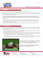
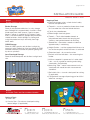
INSTALLATION
GUIDE
Effective March 1, 2012
www.a1rubber.com
Document No. OSMAR12INSTALL
Disclaimer
The installation instructions contained herein are given to the best of our knowledge. It is the installer’s obligation to check for any defects before any products are installed, claims will not be warranted for
any visual defects after installation. A1 Rubber will not warrant any claim due to any actions whatsoever of the installer. In practice, the difference in materials, substrates and actual site conditions are such
that no warranty in respect of merchantability or of fitness for a particular purpose, nor any liability arising out of any legal relationship whatsoever, can be inferred either from this information, or from any
written recommendations, or from any other advice offered. Therefore professional construction advice should be sought in areas that are not covered in this installation guide. A1 Rubber reserves the right
to change the properties of its products. Application, use and interpretation of these instructions are beyond our control and thus full installation responsibility falls exclusively with the installer.
page 1 of 20
INSTALLATION GUIDE
Effective March 1, 2012
Contents
Introduction ...................................................................................................................................... 2
Careful Consideration ....................................................................................................................... 2
Step 1 - Ensure Products are Properly Stored .................................................................................. 3
Step 2 - Assemble Tools and Consumables Needed ........................................................................ 3
Step 3 - Survey the Site ................................................................................................................... 4
Step 4 - Water Collection System ..................................................................................................... 4
Step 5 - Prepare Substrate System .................................................................................................. 5
Step 6 - Test/Inspect Sub-Base ....................................................................................................... 6
Step 7 - Adjust/Prepare Asphalt/Concrete Substrates ...................................................................... 6
Step 8 - Confirm/Assess Site Size and Layout ................................................................................. 7
Step 9 - Base Aeroshockpad Installation ........................................................................................
8
Step 10 - Lay all Shockpads in a Brick Pattern ................................................................................. 8
Step 11 - Install Cut Tiles at Edges of Installation or at Posts and Play Equipment ............................ 8
Step 12 - Complete Final Shockpad Installations ............................................................................. 9
Step 13 - Preparing the Site for the Top Layer Wetpour Rubber Surface Application ........................ 10
Step 14 - Preparing the Mixing Area ................................................................................................. 10
Step 15 - Preparing your Tools and Mixing ....................................................................................... 10
Step 16 - Trowel Runs ...................................................................................................................... 12
Step 17 - Screeding, Tamping and Finishing .................................................................................... 13
Step 18 - Continuing and Blending Trowel Runs .............................................................................. 13
Step 19 - Lap Joining ...................................................................................................................... 14
Step 20 - Finish Edges ..................................................................................................................... 14
Step 21 - Cleaning Rotatub and Tools .............................................................................................. 15
Step 22 - Barrier Tape and Notes ..................................................................................................... 16
Notes for Troubleshooting ................................................................................................................ 16
Appendix One - Australian Standards and Certification Information .................................................. 17
Appendix Two - A1 Rubber Critical Fall Height Graph ....................................................................... 19
Appendix Three - Finishing and Ramping Edges .............................................................................. 20
www.a1rubber.com
QLD
p (07) 3807 3666
f (07) 3807 2344
e [email protected]
34 Binary St, Yatala, 4207
NSW
p (02) 9756 2146
f (02) 9756 2149
e [email protected]
40 Bentley St, Wetherill Park, 2164
VIC
p 0408 607 888
f (07) 3807 2344
e [email protected]
16-24 Berends Dr, Dandenong S, 3157
page 2 of 20
INSTALLATION GUIDE
Effective March 1, 2012
Introduction
OneSafe is the easiest wetpour rubber system to install on the market today.
The use of CSBR rubber crumb in OneSafe surfaces offers excellent colour consistency and therefore a great
looking surface every time. Combining this with Aero Shockpad underlays makes installation super efficient
with predictable performance every time.
The OneSafe system is specified with the use of Procure as the rubber crumb binder. Procure has been
specially formulated to provide excellent elastic properties which is a pre-requisite for any playground surface
and the cure times are formulated for the widest range of atmospheric conditions to minimise the chances of
shrinkage cracks.
The OneSafe system has been extensively tested to exceed the requirements of the Australian Standards for
critical fall heights and has been installed in both commercial and domestic applications, childcare centres,
schools and council parks across Australia.
This document provides step-by-step guidance for the installation of the OneSafe rubber wetpour system.
Careful Consideration
Raw material requirements per square metre vary depending upon the thickness required and the surface the
product is being installed over. Prior to ordering and installation of the OneSafe Surface, careful consideration
needs to be given to the following:
1. Make sure of your critical fall height requirements and choose the AeroShockpad and CSBR top surface
thicknesses correctly. (See Appendix One for more details).
2. Double check the area size to ensure the correct amount of raw materials are ordered. (As a general guide
25kg of CSBR granules will cover approximately two square metres on a flat surface at 15mm thickness).
The A1 Rubber sales staff can assist you further on detailed product usages if required.
3. The OneSafe system is available in a range of colours (see the CSBR colour range on A1 Rubber’s website).
Choose the correct CSBR colour quantities to suit the pattern or plans you have to work to.
A1 Rubber installation assistance does not end with this
installation guide. We are available by phone on 07 3807
3666 from 7.00am to 5.00pm Monday to Friday.
Thank you for choosing the OneSafe rubber wetpour
system for your surfacing requirements.
www.a1rubber.com
QLD
p (07) 3807 3666
f (07) 3807 2344
e [email protected]
34 Binary St, Yatala, 4207
NSW
p (02) 9756 2146
f (02) 9756 2149
e [email protected]
40 Bentley St, Wetherill Park, 2164
VIC
p 0408 607 888
f (07) 3807 2344
e [email protected]
16-24 Berends Dr, Dandenong S, 3157
page 3 of 20
INSTALLATION GUIDE
Effective March 1, 2012
Step 1
Ensure Products are Properly Stored
Required Tools
a) RotaTub wetpour mixer – check that all safety
features are operational
b) Tarpaulin – use as a protective throw down sheet
for use under the mixer and binder buckets
Binder Storage
Store all polyurethane adhesives in a dry storage
area. Storage life is approximately 9 months. Keep
binder away from heat sources, sparks or open
flames. Procure is supplied by A1 Rubber in pails
and it is not flammable but appropriate precautions
should be taken. Avoid spillages by storing and
using the product on tarps and away from high
traffic areas
c) Plastic tray wheelbarrow
d) Elbow length chemical gloves.
e) Trowels – Thick-sided wooden trowels or
polyurethane foam trowels for tamping and
stainless steel pointed trowels for finishing.
CSBR Storage
Store all CSBR granules out of direct sunlight by
covering it with a reflective silver tarp. Keep all CSBR
covered sufficiently to avoid the product getting wet
by rain or sprinklers.
Aero Shockpad Storage
Store all Aero Shockpads out of direct sunlight and
rain.
f ) Screed Bar – Concretors screed cut down to
approximately 1 metre long.
g) Height Guides – use the appropriate thickness to
ensure the required surface thickness is achieved
h) Extension leads - for use on the mixer
i ) Buckets with litre indicators – for measuring the
binder
j ) 600mm carpenter’s square and a 1 metre steel
ruler – use as a guide for marking and cutting
shockpads. (If applicable)
k) Measuring Tape – metric measurement units as
shockpads are made to metric measurement
standards.
l ) Soft chalk sticks – to mark shockpads for cutting.
(if applicable)
m) Single barrel sausage dispensing gun for 600ml
adhesive sausages
Step 2
Assemble Tools and Consumables Needed
Optional Tools
a) Knee Pads
b) Circular Saw – For volume shockpad cutting
around edges. (If applicable)
www.a1rubber.com
QLD
p (07) 3807 3666
f (07) 3807 2344
e [email protected]
34 Binary St, Yatala, 4207
NSW
p (02) 9756 2146
f (02) 9756 2149
e [email protected]
40 Bentley St, Wetherill Park, 2164
VIC
p 0408 607 888
f (07) 3807 2344
e [email protected]
16-24 Berends Dr, Dandenong S, 3157
page 4 of 20
INSTALLATION GUIDE
Effective March 1, 2012
the installation over time. In areas where little or no
moisture is expected to come in contact with the
OneSafe surface (interior non-pool areas), subsurface drainage is not required.
Consumable Items
a) Disposable gloves and rags
b) Duct or masking tape – to protect adjacent
surfaces during your wetpour application.
Orientation
Although the final orientation of the installed surface
may not be a matter of choice, some consideration
should be given to the following items:
c) Polysolv – use as a trowel lubricant, to clean the
mixer and to remove adhesive spots and spills
d) Stanley knife blades or equivalent.
Step 3
Survey the Site
Sub-Surface Drainage
For outdoor OneSafe installations it is important that
the sub-surface drains properly due to the porous
nature of OneSafe.
1.) Naturally Draining Sub-Surface
If the installation site is elevated (higher than
adjacent grades) with natural drainage, and does not
currently collect water, then additional sub-surface
storm water management systems will, more than
likely, not be necessary. The surface water will pass
through the OneSafe surface and then drain across
the top of the subsurface.
2.) Non-Draining Sub-Surface
If the installation area is lower than the adjacent
grades and/or tends to collect water, then a
subsurface water management system must be
installed. If the sub-surface is solid (i.e. concrete or
asphalt) and water collects (deeper than 3mm) on
the surface areas where OneSafe is to be laid, these
areas must be filled with patch materials such as
a fast setting, one component, polymer modified,
cement based, self-levelling pre-mix mortar. (See
surface preparation section).
If the solid sub-surface is surrounding a pool or any
other high water/moisture producing source, it is
important that the sub-surface be sloped a minimum
of 2% toward the water collection drains.
The site owner should be advised if the surrounding
area has drainage problems as this could affect
the sub-base structure or planarity (subsidence) of
www.a1rubber.com
QLD
p (07) 3807 3666
f (07) 3807 2344
e [email protected]
34 Binary St, Yatala, 4207
a) Direct Sunlight
OneSafe is made from recycled rubber. Rubber
absorbs heat from infrared light (i.e. surface heat is
generated from exposure to direct sunlight, not so
much from exposure to atmospheric temperature).
Therefore, if the surface area is exposed to direct
sunlight, design considerations could include shade
sails.
OneSafe, in direct sunlight, typically will have an
average surface temperature that is high. On a bright
sunny day, with direct sun exposure the surface
temperature could be as high as 60°C. On shaded
areas that receive partial shading the surface will be
close to the same temperature as the atmosphere.
b) Continually Shaded or Damp Areas
Installation sites in high humidity and/or shaded
locations may remain continually damp. If warm
temperatures are added to these damp areas the
OneSafe surface may be subject to fungal or mould
growth.
In these conditions, mould has been known to use
the rubber surface as an attachment in the search
for food. The rubber can be penetrated by the
mould searching for a food source, which leads to
polymer degradation and carbon black exposure.
In these scenarios the surface should be maintained
regularly (see maintenance section) by washing with
watered down vinegar and steam cleaning.
Step 4.
Water Collection System (If Necessary)
The following is a guideline for preparing substrates
that do not already have a properly prepared base.
NSW
p (02) 9756 2146
f (02) 9756 2149
e [email protected]
40 Bentley St, Wetherill Park, 2164
VIC
p 0408 607 888
f (07) 3807 2344
e [email protected]
16-24 Berends Dr, Dandenong S, 3157
page 5 of 20
INSTALLATION GUIDE
Effective March 1, 2012
Installed Water Collection System
Carefully survey the site for drainage. Inspect the
area after a rainstorm or test with local water supply.
If this test results in the necessity of installing a
drainage collection system, then complete the
following steps:
a) Excavate trenches to fit perforated agricultural
pipe. Top of Agi pipe should be level with bottom
of intended granular base.
b) Install perforated Agi pipe with correct slope.
Connect ends.
c)Back fill trenches with 19mm clear, crushed
stone. This 19mm stone should wrap the
drainage pipe to a diameter of approximately
300mm.
depends upon the sub-soil density. Typical
requirements are from 50mm to 100mm thick.
(75mm is average). Pack crusher dust with a
vibrating packer or roller.
d)Tie drainage system into existing storm sewer or
ditch. Restore finished surfaces over trenched
areas with appropriate ground cover (grass etc.).
A properly designed and installed water collection
system is often overlooked during OneSafe planning
stages because in many cases a planner fails to give
consideration to the porous nature of the finished
surface. (Concrete and/or asphalt are by far the
most common site surfacing options, where subsurface drainage may not need to be installed.)
If the base is poor and subsidence is possible,
excavate down further until a stable sub base or
300mm of depth is reached. Re-pack the subsurface with compacted road base in 100mm
layers to 95% compaction. Screed and shape the
final layer of the sub-base with crusher dust up to
100mm thick.
d) Enhance crusher dust packing by applying water
NOTE: Due to OneSafes porosity, it is critical that
a proper sub-surface drainage system be planned
and implemented or the OneSafe surface may not
stay level and ultimately may become damaged
due to sub-base subsidence.
Step 5
Prepare Substrate (If Necessary)
a) Mark out perimeter of the safety surface area with
fluorescent paint.
b) Excavate and remove soil/grass
into the surface area.
encroaching
c) The minimum sub-base requirements for a
OneSafe surface requires a compacted crusher
dust surface. The depth of crusher dust required
www.a1rubber.com
QLD
p (07) 3807 3666
f (07) 3807 2344
e [email protected]
34 Binary St, Yatala, 4207
e)Ensure upon completion the sub base surface
is smooth and flowing. Ensure the depth from
concrete paths etc. to the prepared substrate is
the same as the thickness of the rubber system.
NSW
p (02) 9756 2146
f (02) 9756 2149
e [email protected]
40 Bentley St, Wetherill Park, 2164
VIC
p 0408 607 888
f (07) 3807 2344
e [email protected]
16-24 Berends Dr, Dandenong S, 3157
page 6 of 20
INSTALLATION GUIDE
Effective March 1, 2012
f) For applications of OneSafe where no fixed edge
is able to be finished too, a ramp down edge
into the surrounding grass or bark surface will be
required. The edges of the sub-base preparation
need to accommodate this requirement and
therefore require the sub-base edges to be
excavated to allow a gentle transition of the
finished surface to enter and bury into the
surrounds. See Appendix Three.
Step 6
Test / Inspect Sub-Base
During heavy rains water will remain on surfaces with
slopes that are less than 2% due to the flow through
of water through the OneSafe surface. In addition,
water can collect on the sub-base if the planarity
of the surface is not falling or smooth. If/when
significant water volumes cannot escape from the
sub-surface and water backs up under the product,
sub-base subsidence may occur and could result in
a damaged installation. To test slope and drainage,
flood the area with water.
Inspect the sub-surface.
Be sure to inspect the sub-surface for proper
planarity to ensure that the final OneSafe surface will
be smooth & neat in appearance
Sub-base preparation is sometimes completed
under separate contract to the OneSafe installation.
When the sub-base is completed by another
contractor/installer, it is frequently not smooth
enough for an immediate installation of OneSafe
because:
a) In cases where the sub-base is compacted
crusher dust, the sub-base installation contractor
may have left the site smooth and well packed,
but it may have become disturbed prior to the
arrival of the OneSafe installation crew.
www.a1rubber.com
QLD
p (07) 3807 3666
f (07) 3807 2344
e [email protected]
34 Binary St, Yatala, 4207
c) The sub-base installation contractor may not
have taken enough care to get the sub-base
depth at the edges to match the depth of the
rubber system. Solid sub-surfaces that vary in
planarity are not a problem for OneSafe however;
to rectify these situations, add crusher dust to
the depressed areas. If more product is to be
used to achieve a certain finished height, check
with A1 Rubber that the compliance to Australian
standards will not compromised.
d) Remove any other obstructions preventing
complete and unrestricted OneSafe installation.
This includes the removal of debris from a surface
that may have been just removed.
Test the newly installed sub-base.
Be sure to test the sub-base for proper slope in
order to ensure that it will be properly draining.
b) The sub-base installation contractor may not
have taken enough care to get a sub-base
surface to the specified planarity.
Step 7
Adjust / Prepare Asphalt or Concrete Substrates
(If Necessary)
Inspect concrete finishes.
Ensure there are no large cracks and/or loose
materials that can be easily removed.
Concrete should be broomed or blown clean prior
to the OneSafe installation. For installations that do
not require a shockpad underlay ensure that there
are no oils or greases on the surface that may cause
OneSafe to not adhere properly.
Properly prepared asphalt or concrete surfaces are
ideal sub-bases for OneSafe. Adhesion to a hard
sub-base is not necessary but can have benefits.
a) If/when OneSafe is laid on a concrete or asphalt
sub-base, it is important to ensure that these
sub-bases have cured/aged sufficiently. Curing
time can vary by region, temperature and
atmospheric moisture (relative humidity) but it is
normally a minimum of 28 days for both asphalt
and concrete.
b) Ensure concrete/asphalt surfaces are dry if/
when the OneSafe is to be laid on this type
of substrate. It is important to remember that
NSW
p (02) 9756 2146
f (02) 9756 2149
e [email protected]
40 Bentley St, Wetherill Park, 2164
VIC
p 0408 607 888
f (07) 3807 2344
e [email protected]
16-24 Berends Dr, Dandenong S, 3157
page 7 of 20
INSTALLATION GUIDE
Effective March 1, 2012
the single biggest reason for bonding failure is
excess moisture at the time of installation. If the
asphalt/concrete base is wet it must be allowed
to completely dry before installation begins. A
simple “layman’s” moisture test would be to leave
a plastic sheet lying over the floor for 24 hours. If
moisture is visible on the back of this sheet when
it is lifted up and inspected, the floor is still curing
or there is too much moisture from other sources.
c) Mechanically sand/scarify loose particles paint,
plasterboard compound and/or any other loosely
bonded particles that need to be removed by
sanding and/or scraping.
d) Acid etch to enhance cleaning of concrete
surfaces to increases the adhesion by opening
the surface pores of the concrete. Mix 25% acid
by volume to water (1part Acid to 3 parts water).
Wash the entire area with this solution. A light
broom scrub will be sufficient. This will also assist
in removing any spills of diesel and/or oil spills/
stains, which is likely, spilled from the asphalt
installation or concrete finishing equipment. After
the complete area has been acid etched, carefully
rinse the entire surface and allow adequate time
for the concrete to dry completely.
e) Power washing older concrete/asphalt substrates
is recommended. The importance of a clean
surface is often proportionate to the age of the
concrete. If the concrete or asphalt base is new,
it will likely be sufficiently clean to not require
power washing. However, if recent construction
was completed at or near the new concrete,
a careful removal of all construction dust and
other construction contaminants (plasterboard
compound etc.) is essential.
Preparation of Wooden Sub-Surface
a) Wood Surface Types-Plywood or Planks.
Either wooden surfaces can be solid plywood or
deck planking (provided the spaces between planks
do not exceed 6mm). Press-wood, chipboard, flakeboard and most particleboard are not acceptable
wooden substrates.
www.a1rubber.com
QLD
p (07) 3807 3666
f (07) 3807 2344
e [email protected]
34 Binary St, Yatala, 4207
b) Secure Loose Boards.
Secure any loose Boards. Countersink protruding
nail heads. Replace any damaged or rotting wood.
Like all other sub surfaces, make sure the surface is
clean and dry prior to the adhesive installation (see
previous). Sand and scrape loose paint.
c) Caution–Wooden Sub-Surfaces
A wooden subsurface will experience more rapid
deterioration after the rubber surface installation is
completed. Since the wooden surfaces will collect
moisture (due to the porosity of OneSafe), it is
reasonable to expect that more rapid deterioration
than normal of the wooden surfaces will occur.
Wooden sub surfaces can also shrink in times of dry
or drought conditions, this can lead to cracks in the
OneSafe surface
Concrete fibreboard and/or extruded, recycled
plastic timber are ideal substitutes for traditional
“wooden” sub-surfaces.
Step 8
Confirm / Assess Site Size and Layout
Confirm Adequate Materials to Complete the
Installation
It is important to have enough products to complete
the entire installation in a single installation session
for the following reasons:
a) To Reduce Effect of Colour Change
OneSafe like new wood, concrete, asphalt or any
coated surface will change colour, over time, with
exposure to UV. This change is not significantly
noticeable when the whole installation changes
colour equally. However, like installing a new
piece of wood beside an older one, there will be
a noticeable difference in the tone of the colour.
OneSafe installed after several UV exposure days will
be visibly different than any newer OneSafe.
b) For Installation Conditions & Efficiency.
Installing OneSafe at one setting ensures similarity in
installation conditions and efficiency.
NSW
p (02) 9756 2146
f (02) 9756 2149
e [email protected]
40 Bentley St, Wetherill Park, 2164
VIC
p 0408 607 888
f (07) 3807 2344
e [email protected]
16-24 Berends Dr, Dandenong S, 3157
page 8 of 20
INSTALLATION GUIDE
Effective March 1, 2012
tiles should be run in the same parallel direction to
the first row but this row of tiles should be offset
started approximately halfway down the adjacent
tile. This will give the tile installation a brick pattern.
NOTE: The closer you can place the shockpads
and OneSafe raw materials to the job site the
faster and easier the installation will be.
Step 9
Base Aero Shockpad Installation
*IF SHOCKPADS ARE NOT REQUIRED,
PROCEED TO STEP 14
Determine starting position.
AeroShockpads are available in Slow Rebound
Protection - SRP (30% polystyrene beads added) or
solid rubber (100% 4 mesh rubber buffings). Both
types offer consistency in density and thickness
whilst the SRP version offers a lower percentage
of rebound intensity (reduces risks of long bone
fractures). Both products offer guaranteed on
site performance for compliance to Australian
Standards. Both the SRP and 100% rubber Aero
Shockpads are suitable for installations over
any substrate, including crusher dust, concrete
and timber floors. Additionally Aero Shockpads
offer very fast installation times in comparison to
trowelled shockpad layers. To determine the most
advantageous position of the first continuous
row of Shockpads include all of the following
considerations:
a. Ensure that the cut edges around the entire
perimeter of the installation will be equal in size.
b. The first-continuous-row of tiles should be run
through the area that requires the least cutting
around posts and other structures.
c. A popular starting position is to run down the
length of any fixed straight edging that the job
may finish against such as a patio edge etc.
Step 10
Lay all Shockpads in a Brick Pattern
Aero Shockpads should be installed in a runner
bond (brick) pattern. The second run of continuos
www.a1rubber.com
QLD
p (07) 3807 3666
f (07) 3807 2344
e [email protected]
34 Binary St, Yatala, 4207
Lay all full tiles up to the job perimeter or equipment
poles and never continue a row of tiles past a
pole without first installing the cut-in-tile. Continue
running the Aero Shockpads down adjacent and
offset to the last installed row of tiles until the entire
area is covered.
Step 11
Install Cut Tiles at the Edges of the Installation or
at Posts and Play Equipment
Marking Tiles for Cutting
Install the shockpad in its desired position
overlaying the perimeter of the installation. Where
the Shockpad passes the perimeter, mark with
a suitable marking chalk on both edges where it
crosses. If the to-be-cut tile needs a straight cut,
mark from one side of the tile to the other using a
straight edge between your original markings. If the
cut is to be curved, take additional measurements
at 200mm intervals along the perimeter until a curve
can be accurately marked.
Cutting shockpads
Straight lines or curved perimeter cutting. Use a fine
tooth timber circular saw (handyman type) to rip
NSW
p (02) 9756 2146
f (02) 9756 2149
e [email protected]
40 Bentley St, Wetherill Park, 2164
VIC
p 0408 607 888
f (07) 3807 2344
e [email protected]
16-24 Berends Dr, Dandenong S, 3157
page 9 of 20
INSTALLATION GUIDE
Effective March 1, 2012
through shockpads. To set up for cutting, adjust
the blade depth of the saw to 5mm less than then
shockpad thickness. Simply rip the saw through
the tile in a fast continuous motion (over cutting the
mark where necessary for a Force Reduction Tight
Fit - see important notes in step 13). The shockpad
can be positioned and cut anywhere, i.e., on the
grass, other shockpads or on a cutting table as
long as the saw never protrudes the depth of the
shockpad being cut.
each Aero Shockpad tile is forced hard into each
adjacent tile in both directions (without leaving
crusher dust between the joins). This can be
achieved by force reducing all tile rows by pushing
from one end on the last tile to allow for the last tile
to then be cut oversize to its actual requirements.
Any contraction of the AeroShockpads in the cool
night temperatures will be compensated by the
memory expansion of each tile installed under a
Force Reduction Tight Fit.
Cutting around poles or objects.
Once the tile is marked for cutting, experienced
applicators simply tear away by hand the desired
pole size and saw or tear to the tiles edge. Optionally
a serrated jigsaw or Stanley knife can be used for
more accurate cutting.
Fill in’s.
When only small slivers or chunks of shock pad
material is needed (assuming a shockpad portion is
not capable of being installed) simply crumb up by
hand off cuts of shockpads and press firmly into and
around the area to be filled. Alternatively, a mixed
batch of 4 mesh buffings can be troweled in, which
is also good for ramping down when necessary.
Adhesive Seaming
Adhesive Seaming of shockpad joins is only
necessary where the Force Reduction Tight Fit
method was not possible and/or as extra security to
ensure gaps between each shockpad don’t occur
during contraction when an unfinished job goes into
a cool night temperature.
To seam the shockpads with adhesive use Sikaflex
221 polyurethane adhesive and the appropriate
dispensing gun. A bead of Sika approximately 8mm
in diameter should be run down all tile joins.
Step 12
Complete Final Shockpad Installation
Compensate for expansion & contraction.
Use the Force Reduction Tight Fit method to
compensate for expansion and contraction of
AeroShockpads.
Shockpads, like any other rubber product, will
expand and contract with temperature and
atmospheric moisture changes. Tiles exposed to
the sun (warmer) will be larger than tiles in the shade
(cooler). Tiles laid in the morning at say 15°C will
be smaller (cooler) than the same tiles laid in the
afternoon at say 30°C.
To minimise the effect of tile contraction in the
evening after installation in warm conditions ensure
www.a1rubber.com
QLD
p (07) 3807 3666
f (07) 3807 2344
e [email protected]
34 Binary St, Yatala, 4207
Generally if two applicators are available one should
be the designated applicator of the adhesive and
the other the designated spreader. Spread the
adhesive by using a 100mm wide scraper tool to
follow behind and spread and force the adhesive
into the joins and its porous rubber sanctions. All
joins and cuts, vertical and horizontal should be
adhesive seamed when performing this application.
NSW
p (02) 9756 2146
f (02) 9756 2149
e [email protected]
40 Bentley St, Wetherill Park, 2164
VIC
p 0408 607 888
f (07) 3807 2344
e [email protected]
16-24 Berends Dr, Dandenong S, 3157
page 10 of 20
INSTALLATION GUIDE
Effective March 1, 2012
Dispensing tips should be cut at approximately
8mm diameter or greater. Approximately 18 to
20 lineal join metres can be seamed per adhesive
sausage. Allow approximately 1 hour for curing in
favourable conditions. Once the adhesive has cured
satisfactorily the Aero shockpads are ready to have
a top layer wetpour rubber surface applied.
applicator. Once it is determined and agreed that a
design is achievable mark out where colour changes
will occur using soft chalk.
Step 14
Preparing the Mixing Area
Use tarps under your mixer.
When choosing your Rotatub mixing area make
sure the mixer is able to be placed on flat stable
ground and power is accessible. The closer the
mixer is to the job the easier the installation will be.
Place throw-down tarps under your mixing area,
between the mixer and the job and anywhere where
your wheelbarrow will traverse and contamination
of the customer’s surface could be a problem. The
wheelbarrow will carry the mixed rubber to the
applicators on the job site and therefore the wheel
usually gets binder on it. Use throw tarps to avoid
any damage to the customers surrounds.
Check that your mixer is clean and all safety devices
are in place. Test the mixer before placing your
ingredients in the bowl to ensure the mixer is in good
working order.
Step 13
Preparing the Site for the Top Layer Wetpour
Rubber Surface Application
Blow site clean.
Using a blower, blow any loose contaminates from
the surface including loose rubber, leaves and similar
debris. Ensure no matter what the top wetpour layer
is to be trowelled over it is clean and free of solid
protrusions that may penetrate through the intended
depth of the wetpour layer.
Step 15
Preparing your Tools and Mixing
Measure and mark out the design
OneSafe surfaces usually require colour changes
throughout the surface to stimulate the play
environment. Some OneSafe surfaces will require
complex designs, patterns and colours to be
installed. Unfortunately in most cases the applicator
can only get close to the requirements of complex
designs due to the limitations of working time and
minimum batch/mix weight requirements.
Careful consideration should be given to the actual
ability of the applicator to deliver the design request
within the capabilities of both the product and the
www.a1rubber.com
QLD
p (07) 3807 3666
f (07) 3807 2344
e [email protected]
34 Binary St, Yatala, 4207
Lube your tools
Usually one to two litres of Polysolv in an open
top metal tin is sufficient to lay 100 square metres
NSW
p (02) 9756 2146
f (02) 9756 2149
e [email protected]
40 Bentley St, Wetherill Park, 2164
VIC
p 0408 607 888
f (07) 3807 2344
e [email protected]
16-24 Berends Dr, Dandenong S, 3157
page 11 of 20
INSTALLATION GUIDE
Effective March 1, 2012
of OneSafe top Layer wetpour. Refer MSDS for
Polysolv safety precautions. A small rag is soaked
in the Polysolv then used to apply a thin coating to
the underside of the Screed Bar, the trowels and the
Height Rods. Lubricant [Polysolv] is continuously
applied as necessary throughout the installation to
avoid binder build up and to lubricate the tools for
free flowing trowel usage.
Mixing
Place the wheelbarrow sideways under mixer
discharge shute before adding the CSBR rubber and
the Procure binder.
Plan your mix ratio of binder to rubber.
The binder ratio is 20% of the CSBR rubber weight.
An allowance needs to be made here for the binder
dreg weight that will remain in your plastic measuring
bucket. Generally approximately 300grams is left
in the bucket when the mixer operator holds the
bucket inverted long enough. A weight can be taken
prior to pouring and after pouring to determine
this weight accurately; it is significantly variable in
accordance with the pour allowance time.
EXAMPLE: 25kg CSBR x 20% = 5kg of Procure +
300g dreg. Total 5.3kg of Procure binder.
Mark on the measuring bucket a height the correct
weight of Procure will reach. Always fill to that mark.
Remember repeated accuracy with the binder is
paramount to avoid potential product failure.
Mixer capacity
Rotatub 25 can mix one 25kg bag of rubber plus
binder and Rotatub 50 can mix 50kg of rubber and
binder.
Adding ingredients to the mixer
Place the CSBR rubber onto the locked down mesh
lid of the mixer and using a knife slice open the bag
and empty the entire contents of the 25kg bag into
the mixer. Choose how many bags to add subject
to your mixer capacity and/or how much material
is needed. If a colour blend is required ensure the
blend formula remains the same for every mix.
NOTE: Minimum mix capacity irrespective of the
Rotatub size is 10kg of rubber plus binder.
Pour the correct amount of Procure binder either
through the mesh lid or into the bowl with the lid
open. It is more efficient to pour through the lid, but
this adds an additional cleaning task later. Avoid
pouring the binder onto the centre mixer shaft with
binder pouring preference given to the outer wall
of the bowl as the blades can mix it through more
effectively.
Press the start button on the mixer and mix the
ingredients for three and a half minutes. Ensure
at the end of the mix time the CSBR rubber is
adequately mixed and appears fully wetted out by
the binder. Increasing the mix time slightly is possible
as long as it is repeated accurately to avoid varying
Binder Film Build.
NOTE: Binder Film Build is the thickness of binder
encapsulating each particle of rubber.
Common wetpour binders are aromatic and
therefore turn yellowish with UV exposure. This
yellowish film affects primarily white, grey and light
blue shaded colours. It can also affect any colour
type from mix to mix if the Binder Film Build varies.
The longer the ingredients are mixed the thicker
the Film Build becomes due an increase in binder
viscosity from the curing reaction. A thicker than
normal Film Build of binder will make the surface
look darker than a normal.
www.a1rubber.com
QLD
p (07) 3807 3666
f (07) 3807 2344
e [email protected]
34 Binary St, Yatala, 4207
NSW
p (02) 9756 2146
f (02) 9756 2149
e [email protected]
40 Bentley St, Wetherill Park, 2164
VIC
p 0408 607 888
f (07) 3807 2344
e [email protected]
16-24 Berends Dr, Dandenong S, 3157
page 12 of 20
INSTALLATION GUIDE
Effective March 1, 2012
Avoid circumstances where the wetpour rubber
laying applicator is not ready for the delivery of the
next mix. In this case don’t continue mixing past
your standard mix time. If the applicator can’t use
the mix reasonably quickly the mix may have to be
discarded to avoid a potential colour variation from
Binder Film Build variance.
job site in a continuous manner. They are the only
method of continuous applicator access to smooth
out and blend the wet rubber for a seamless
surface. Choosing the best place and direction to
start trowel runs is determined as the narrowest
width of the job and at the furtherest point away
from the wheelbarrow [mixture] entry for the job.
Preference should be given where possible to
running the trowel runs across the narrowest width
of the site to ensure the applicators can get back
to the wet edge of the pour within the shortest time
possible.
Before discharging the rubber from the mixer,
inspect the mixture to ensure the product is
consistent without dry lumps or dry pockets. Once
it is determined that the mix is satisfactory, whilst
the mixer is still running push down on the mixer
discharge handle and swing open the trap door
allowing the rubber to pour into the wheelbarrow.
Spread the rubber into the wheelbarrow as
necessary to make it fit as needed. Do not put
anything including hands up into the discharge hole
of the mixer to help discharge the mixture.
The width of OneSafe trowel runs should be
approximately 500mm with the length being
determined by the amount of mixture made per
batch. This ensures the applicator can successfully
reach and lean over to blend in the join of each
trowel run.
NOTE: See Rotatub User Manual for mixer safety,
operational instructions and functions.
Step 16
Trowel Runs
Choose the best starting point
Trowel Runs are an application procedure for
playground surface wetpour rubber incorporating
narrow strips of the poured rubber run across the
www.a1rubber.com
QLD
p (07) 3807 3666
f (07) 3807 2344
e [email protected]
34 Binary St, Yatala, 4207
NOTE: The longest time a wet OneSafe edge
should be left before blending/joining the next
trowel run in is 15 minutes.
If this is not achieved it may be hard to blend in the
next trowel run, leaving the workmanship in the
join susceptible to separation from expansion and
contraction over time. This is why it is recommended
to run the trowel runs across the narrowest
dimension of the job, to ensure the fastest possible
return to the wet edge.
NSW
p (02) 9756 2146
f (02) 9756 2149
e [email protected]
40 Bentley St, Wetherill Park, 2164
VIC
p 0408 607 888
f (07) 3807 2344
e [email protected]
16-24 Berends Dr, Dandenong S, 3157
page 13 of 20
INSTALLATION GUIDE
Effective March 1, 2012
Step 17
Screeding, Tamping and Finishing
Height Measurement Guides
Height Measurement Guides can be any material as
long as they are slightly flexible and the right height.
Apply Polysolv to the Height Guides as needed with
a small rag to avoid product build up. Thin timber
stripping is suitable and they can be purchased
through hardware outlets at varying thicknesses.
For example, for a 15mm thick OneSafe top layer,
use an 18mm Height Guide. Height Guide usage is
critical to maintain the correct thickness top layer
throughout the installation.
Place the Height Guides 500mm apart, parallel to
one another on the sub-base or shockpads in the
direction of the desired trowel run. Pour the rubber
mixture from the wheelbarrow in between the Height
Guides where necessary so the mixture can be
easily screed out in between the guides. With the
screed firmly sitting on the Height Guides, use a
sawing motion to cut and move the rubber mixture
along in between the guides until an evenly spread
and consistent loose pour is achieved. Once the
correct pour height and consistency is achieved
remove the guides for Impact Tamping.
Impact Tamping
Impact tamping is performed to compact all the
loose particles of rubber mixture into a tight fit.
Impact Tamping requires the applicator to tamp
the surface with a lubricated [Polysolv] thick bodied
trowel whilst keeping the trowel flat at impact.
Enough force needs to be applied to connect
the particles of rubber closely together without
compromising the planarity of the surface.
This is best achieved via applicator feel and the
end result required. After tamping 15mm surface
thickness should be achieved if an 18mm Height
Guide was used. This can be checked by doing a
depth check through the wet mixture with a short
length of 6mm diameter dowel marked accordingly.
The tamping method is also used for moving the
granules slightly sideways if necessary.
www.a1rubber.com
QLD
p (07) 3807 3666
f (07) 3807 2344
e [email protected]
34 Binary St, Yatala, 4207
If an area of the pour needs to be thinned out, hitting
down on the surface with a sideways impact causes
the granules to move in the direction you require.
Add amounts of mixture as necessary to any areas
of the pour that need filling. This includes any small
porous looking spots that need a only a very small
amount.
Finishing
For a top surface free of lines and loose particles,
use a ‘pointing’ steel trowel with the rear ends bent
up (to prevent trowel gouging). Lightly lubricate the
trowel with a rag soaked in Polysolv and wipe off any
drips. Be sure not to flood the trowel with lubricant
to avoid washing the binder out of the mixture.
Holding your trowel on a slight upward angel to the
direction trowelling in, smooth out in a side to side
motion any lines and loose particles that may have
been left by the tamping procedure. If any porous
spots are found at this time they can be filled by
adding more mixture as necessary. It is important to
keep your trowel lubricated sufficiently to avoid reseparation of the rubber particles.
Step 18
Continuing and Blending Trowel Runs
Blend trowel runs thoroughly
There are two areas where wet blends are required
for continuing on with trowel runs; the width blend
(shortest side) and the length blend (longest side).
Using a tool, drag along the wet edge of the trowel
run lightly to loosen up the edge for blending (Height
Guide strips work well for this). Continue on trowel
runs following the normal Screed, Tamp, Finish
method by placing the Height Guides alongside
for width (shortest) continuation running and one
guide approximately 500mm out for length (longest)
continuation trowel running.
Pour the next mixture out evenly and screed it to
height using the Height Guides, then follow the
previous tamping and finishing steps. To blend
the runs, using the tamping float, tamp down on
either side and on top of the join with slight sideways impacts pushing the particles back and forth
NSW
p (02) 9756 2146
f (02) 9756 2149
e [email protected]
40 Bentley St, Wetherill Park, 2164
VIC
p 0408 607 888
f (07) 3807 2344
e [email protected]
16-24 Berends Dr, Dandenong S, 3157
page 14 of 20
INSTALLATION GUIDE
Effective March 1, 2012
together to blend the join and fill any porous spots.
This should create a top surface with minimal visible
signs of joining. It is important that all joins are
blended thoroughly whilst still wet to obtain uniform
surface strength. If trowel runs are blended late, the
mixture may be difficult to blend and the trowel joins
may be susceptible to cracking in due course with
daily thermal expansion and contraction. Continuous
application of the mixture in manageable size trowel
runs and blending as you go will result in a seamless
appearance over the entire area required.
Place the edge of a lubricated trowel approximately
20mm to 30mm in from the edge of the pour, then
firmly press down to half depth of the pour and pull/
drag the trowel away from the edge, spreading the
pour out until it is ramped off to completely flat.
50 - 100mm
50%
Step 19
Lap Joining
Wetpour
Shockpads
Use Lap Joins to change colours or for joining
Lap joints increase the surface area contact between
a previously cured edge and a new wet edge. Wet to
wet lap joins are possible during colour changes to
ensure positive contact between the two wetpours.
Lap joints are to be used when the site to be poured
is larger than the toweling capacity of the crew
within the one period.
Displaceable Media
Continue this method along the entire edge including
cornering where needed. Various hand/trowel
methods can then employed to ensure a clean
squared off top edge remains to trowel back up too.
NOTE: When joining up to a wet lap joint
particular care needs to be taken to not disturb or
contaminate the adjacent surface.
Step 20
Finishing Edges
Lap joints look like a continuous moulded small step
at the edge of the pour. The depth of the step is half
of the expected finished height of the top layer pour
with the base of the step flaring out at least 50mm
but not more than 100mm. To mould in a lap joint
the squared off, full depth edge of the pour needs
to be slightly proud of the expected finish pattern.
www.a1rubber.com
QLD
p (07) 3807 3666
f (07) 3807 2344
e [email protected]
34 Binary St, Yatala, 4207
Edge Types.
Various edge options are available to suit every
application. Rampdown edges include those finished
into grass, bark or sand perimeters. Ramping the
OneSafe surface down into the perimeter reduces
the risk of the edge being exposed to vandalism
and reduces any potential water flow excavating
the edges of the prepared sub-base works. See
Appendix Three for more info. Fixed Edges are those
finished up to hard surrounds like concrete or timber,
and Rolled Off Edges are used where the surface is
to be finished off on a hard surface like concrete.
Ramping into Grass
If the installation requires that the edge works be
finished into grass you will need to ramp 100mm
NSW
p (02) 9756 2146
f (02) 9756 2149
e [email protected]
40 Bentley St, Wetherill Park, 2164
VIC
p 0408 607 888
f (07) 3807 2344
e [email protected]
16-24 Berends Dr, Dandenong S, 3157
page 15 of 20
INSTALLATION GUIDE
Effective March 1, 2012
down below the grass surface level around the
perimeter of the installation. If Aero Shockpads are
being used, allow them to follow over the edge
into the excavated perimeter. Finish the pour off
by toweling down into the excavated perimeter as
needed. Once the surface is fully cured the edges
can be back filled and suitably re-turfed.
weight [foot traffic] applied along the edge of the
rubber will break away any adhesion that may
have been present with the fixed edge. Therefore if
adhesion is required a polyurethane mastic sealant
can be applied between the cured rubber and the
fixed edge. When troweling up to a fixed edge
simply trowel the OneSafe surface up to the edge
keeping the top surface level with the fixed edge to
avoid creating a trip hazard. Use a guide line when
troweling along walls to ensure a neat straight height
will be achieved.
Ramping into Sand or Bark
For bark or sand filled perimeters these are
approximately 300 depths and commonly fall
within the play equipment fall zones. The OneSafe
surface including the Aero Shockpad layer needs
to ramp right down to the sub-base level to
ensure compliance if the loose-fill material is either
excavated or low requiring topping up. The Ramp
angle of the sub-base should not exceed 45
degrees and the transition should smoothly roll off
into the loose-fill.
Fixed Edge Adhesion
It is not recommended to apply binder to any fixed
edge to get better adhesion as this may lead to
cracking in your surface further out from the edge
if the surface is trying to contract away from the
edge prior to full cure. A highly elastic adhesive is
recommended to adhere any edges once cured.
Fixed Edge Consideration
When finishing a pour up to a patio or similar type
aesthetic edge, consideration should be given to
the requirement of masking the top side of the fixed
edge to avoid binder contamination.
Edge Gaps, a Common Problem
Commonly, surrounding surfaces like OneSafe are
required to slope away from patios, building walls
and similar hard surfacing for drainage requirements.
Unfortunately this can aid in the surface gently
slipping away over time leaving an unsightly gapping
between the surfaces. Similar problems occur with
rubber surfaces that are surrounded by un-fixed
concrete edging that can move away on the subbase leaving gapping. There are no guaranteed
methods of rubber application to avoid these
problems however, purpose designed extruded
edge strips are available from A1 Rubber along
with polyurethane gap fillers for use as and when
necessary in this situations.
Troweling up to fixed edges
Generally there is insufficient binder contact with
fixed edge surrounds to guarantee adhesion due
to the particulate nature of the mixture. Additionally
the OneSafe surface is compressible so a heavy
www.a1rubber.com
QLD
p (07) 3807 3666
f (07) 3807 2344
e [email protected]
34 Binary St, Yatala, 4207
Hard Substrate Edges
Determining the ramp down length onto hard
substrates is subject to the thickness of the OneSafe
surface and the requirements of the site/customer.
To finish any length ramp-down edge the finished
edge line must be determined first. Once this is
known the ramp can be finished at no greater
angle than 20 degrees. If the OneSafe surface is
only 15mm thick a minimal length ramp is required
however, to finish off any OneSafe edge to a hard
substrate it should not be troweled any thinner
than 8mm to provide a strong leading edge. This
is performed by holding a lubricated steel trowel
vertical on the substrate whilst resting at the edge of
the pour then rolling it over onto the mixture to roll
off the edge of the pour. If high traffic is expected,
once the surface is cured, a light brush on coat of
binder can be applied to the edge of the rubber up
to 50mm in/wide.
Step 21
Cleaning Rotatub and Tools
Cleaning up at the end of the job makes for an
easy start up the next day
Place the wheelbarrow under the Rotatub mixer, and
NSW
p (02) 9756 2146
f (02) 9756 2149
e [email protected]
40 Bentley St, Wetherill Park, 2164
VIC
p 0408 607 888
f (07) 3807 2344
e [email protected]
16-24 Berends Dr, Dandenong S, 3157
page 16 of 20
INSTALLATION GUIDE
Effective March 1, 2012
then using the left over Polysolv [lubricant], pour it
around the inside of the mixing bowl, over the blades
and shaft while the mixer is running. Once fully
wetted out with Polysolv, open the discharge door
allowing the Polysolv and leftover materials to flow
into wheelbarrow.
Loosen the nut/wing-bolt on top of the mixer
shaft, lift shaft out of bowl and place it in your
wheelbarrow. Slide off the mixer paddles and
the discharge guard from the outlet and clean
thoroughly. Using a rag wipe all remaining Polysolv
and rubber out of bowl leaving it to clean and dry.
Once the Rotatub is clean place the paddles and
shaft back into bowl and re-assemble. Place tools
in wheelbarrow and clean as well. Cleaning your
Rotatub mixer and tools thoroughly ensures that
they won’t build with polyurethane.
Step 22
Barrier Tape
surface to determine whether it feels fully cured will
be necessary in this case.
Notes for Troubleshooting
NOTE: Laying wetpour in outdoor conditions
is subject to various surface failure types if the
conditions of the day are not considered.
Recycled tyre rubber fights off U.V degradation by
converting the radiation into heat via the carbon
black used in tyre manufacture. This heat excites the
rubber particles expanding their size causing thermal
expansion. During installation the rubber surface
being trowelled (and the shockpad layer) can expand
or contract with exposure to temperature change or
direct sunlight followed by shade.
Rubber surfaces on a 30˚C low humidity day, in
direct sunlight, can reach surface temperatures
of 60˚C, whereas in 100% shade the surface is
generally at ambient temperature. Therefore surface
temperature drops of more than 50% do happen
when the surface goes from direct sunlight to
direct shade. Shade can be from sails, a fence or a
building etc. This is a problem when the surface has
just been trowelled, as a slight contraction fracture
can occur because the binder has not reached a
strong enough cure.
Therefore shockpad and top surface layers can
expand and contract significantly during installation
and curing when exposed to varying surface
temperatures. High humidity days offer stable lower
surface temperatures as the UV radiation is lower.
Place barrier tape around the finished OneSafe
job-site until fully cured. Full curing before the
surface should be used is approximately 24 hours
in moderate temperates and humidity. In some
cases, where there is a known risk of traffic across
the surface prior to curing, it may be necessary to
contract a security services company [or similar] to
ensure the surface is fully cured before use. In cold
conditions with low humidity the surface may need
up to 48 hours for full cure. An inspection of the
www.a1rubber.com
QLD
p (07) 3807 3666
f (07) 3807 2344
e [email protected]
34 Binary St, Yatala, 4207
It is important to understand and predict any
thermal movement by considering the environment
on the day planned to wet pour the top surface
layer. Failure to predict and adjust for the thermal
movement of both the shockpad layer (either
trowelled or prefabricated) and the uncured wet pour
top surface layer can result in Thermal Contraction
Surface Cracks (TCSC).
The later in the day a surface is trowelled, the
less time it has to achieve a strong enough bond
before the cool of the evening sets in. If trowelling is
NSW
p (02) 9756 2146
f (02) 9756 2149
e [email protected]
40 Bentley St, Wetherill Park, 2164
VIC
p 0408 607 888
f (07) 3807 2344
e [email protected]
16-24 Berends Dr, Dandenong S, 3157
page 17 of 20
INSTALLATION GUIDE
Effective March 1, 2012
completed by say 4.00pm, and the temperature is
cool, say 15˚C, and the surface is in direct sunlight,
the rubber can reach temperatures up to 30˚C
when the humidity is below 50% (eg. winter). Going
into evenings like this the temperature can drop to
approximately 5˚C or less. In these conditions the
binder cure time will extend out usually all night until
the temperature and humidity increases the next
day. In this case the entire surface will be exposed
to contraction from the significant temperature drop
– whilst in an uncured state because trowelling was
finished so late in the day. This is a typical example
of a surface that will suffer from TCSC.
A TCSC generally causes a barely visible surface
crack initially, which then over a reasonably quick
time exposes itself as a larger crack after surface
use, extreme cold temperatures or daily thermal
expansion and contraction. If a surface fails by
TCSC they usually appear in the following places:
Taking all of the above into consideration the best
time to install a top surface wetpour layer is generally
when the temperature of the day or the surface
temperature of the rubber is on the increase. An
allowance of time for curing should be made before
predicted temperature drops based on the surfaces
direct exposure to sunlight, the humidity and the
ambient temperature of the day.
NOTE: Never wet a freshly laid wetpour surface to
speed up the cure time before a temperature drop
or to reduce traffic risk before curing.
Top layer wetpour cannot be laid in the rain and
should not be exposed to rain prior to green cure. If
a freshly laid surface is subject to any rainfall, the the
binder cure rate increases as it is moisture curing.
The curing reaction causes carbon monoxide cells to
form within the binder film (like foaming) between the
particles of rubber. This makes the bond between
the rubber particles foamy and weak. This surface
www.a1rubber.com
GD can also be caused by the use of damp or
sweaty rubber crumb. Product that is left in the the
rain or weather for long periods of time can hold
moisture in the bags and cause condensation to
form on the rubber particles. In this case, once
mixed, the cure time of the mixture will generally be
reduced to only a few minutes before the mixture
becomes unworkable. It is advisable to discontinue
the application at this stage as the blending of the
trowel runs will become problematic.
Appendix One
Australian Standards & Certification Information
- Colour change join lines or cut-in patterns
- Trowel run batch line joins
- Base layer thickness changes
- Base layer joins
- Where base layers end
QLD
p (07) 3807 3666
f (07) 3807 2344
e [email protected]
34 Binary St, Yatala, 4207
once used will fail by Granular Delamination (GD).
GD is where the top layer particles delaminate from
there bond and lay loosely all over the surface.
Certification of Compliance
Introduction
The Australian Standard AS/NZS 4422:1996
specifies testing requirements to determine the
Critical Fall Height (CFH) for playground safety
surfaces. The CFH is determined by dropping an
instrumented headform from various heights onto
the surface and measuring the point where one of
two safety criteria are exceeded; those criteria are
the Head Injury Criterion exceeding 1000, and the
maximum acceleration due to the impact exceeding
200g. Heights tested include those which produce
measurements that satisfy the relevant criterion and
those which exceed the relevant criterion.
A1 Rubber’s Products
A1 Rubber manufacture a range of surfacing
products for playgrounds. For many years A1
Rubber has been at the forefront of global innovation
in impact attenuation performance.
Our commitment to research, product development
and factory controlled manufacture in this area has
resulted in guaranteed on-site surface compliance to
Australian Standards.
All of A1 Rubber’s playground surfacing products
(in varying thickness and densities) have been
subjected to thousands of impact tests to
NSW
p (02) 9756 2146
f (02) 9756 2149
e [email protected]
40 Bentley St, Wetherill Park, 2164
VIC
p 0408 607 888
f (07) 3807 2344
e [email protected]
16-24 Berends Dr, Dandenong S, 3157
page 18 of 20
INSTALLATION GUIDE
Effective March 1, 2012
determine the best product specifications for the
Standards criteria. An easy-to-use ‘Critical Fall
Height Graph’ has been mapped from our test data
which represents the relationship between surface
thickness and Certified Fall Heights.
elevated heights.
Applicable surface types
The Critical Fall Height Graph applies to the following
A1 Rubber full playground surface systems:
Rubberise – CSBR over Aero Shockpad Underlays
The ‘Critical Fall Height Graph’ values only apply
to products supplied and installed as specified by
A1 Rubber. An allowance has been made for slight
variations in top layer trowelling, ageing, some
temperature variation, some wear and moisture
but not for degradation, damage, contamination,
hardening of the substrate or significant wear of the
product after installation and use on site.
Standard Wetpour – Oxide coloured wetpour over
Aero Shockpad Underlays
EPDM – EPDM over Aero Shockpad Underlays
AeroCool – AeroCool tiles and coatings over Aero
Shockpad Underlays
Plātile – Plātiles over Aero Shockpad Underlays
Substrates
Varying substrate types do affect testing results
of impact attenuating surfacing systems. Subbases such as crusher dust displace with impact.
Accordingly displacement substrate values are
shown on the graph. It is recommended that an
allowance for hardening of displaceable substrates
[often caused by drought] be made by the specifier.
Synthetic Grass – Synthetic grass over Aero
Shockpad Underlays
Note: A standard 19mm sand filled synthetic
grass layer offers no benefit or detriment to the
CFH value and therefore no thickness inclusion is
apportionable to the overall system. Some high
density short pile synthetic grasses have a slight
benefit to the value by approximately 5mm.
How to use the Graph (Appendix Two)
The surface thickness’ are shown at the bottom of
the graph. The CFH values are shown vertically on
the side of the graph. The determination for a CFH
relating to the play equipment is always specified
by the manufacturer of the equipment or the
playground architect.
Conclusion
The objective of the Australian Standard 4422:1996
is to minimise the severity of head injury resulting
from a fall. The standard gives a method of test
by which impact attenuation can be determined
on surfacing products. From these Critical Fall
Height tests results can be mapped (see graph)
that represent the upper limits in effectiveness for
reducing head injury from falls onto these products.
To determine the surface thickness from the known
CFH value simply follow the line across from the
CFH value until it meets the mapped test result line
and follow it vertically downwards to determine the
thickness required.
Determining the surface layers thickness’
All thickness values shown on the graph are for the
combined thickness of the top surface layer and the
shockpad layer. Our rubber playground systems
require the top surface layer thickness target to be
15mm up to the total surface thickness of 65mm.
Surfaces which are a total of 70mm or thicker
require the top layer to be increased to 20mm.
Following this guideline offers the best surface
support and strength during an impact event from
www.a1rubber.com
QLD
p (07) 3807 3666
f (07) 3807 2344
e [email protected]
34 Binary St, Yatala, 4207
The values shown in the graph (Appendix Two) have
been determined from test results as required by
the standard. Certification of conformance to the
standard in the form of a ‘Certificate of Compliance’
can be provided by A1 Rubber after completion for
each specific site. Please don’t hesitate to contact
A1 Rubber if you require further information on this
subject.
NSW
p (02) 9756 2146
f (02) 9756 2149
e [email protected]
40 Bentley St, Wetherill Park, 2164
VIC
p 0408 607 888
f (07) 3807 2344
e [email protected]
16-24 Berends Dr, Dandenong S, 3157
page 19 of 20
INSTALLATION GUIDE
Effective March 1, 2012
Appendix Two
A1 Rubber Critical Fall Height Graph
3.5
3.4
3.3
3.2
3.1
3.0
2.9
2.8
2.7
2.6
2.5
2.4
2.3
Critical Fall Height (m)
2.2
2.1
2.0
1.9
1.8
1.7
1.6
1.5
1.4
1.3
1.2
1.1
1.0
0.9
0.8
0.7
0.6
0.5
0.4
0.3
0.2
0.1
0.0
0
10
20
30
40
50
60
70
80
90
100
Surface Thickness (mm)
www.a1rubber.com
QLD
p (07) 3807 3666
f (07) 3807 2344
e [email protected]
34 Binary St, Yatala, 4207
NSW
p (02) 9756 2146
f (02) 9756 2149
e [email protected]
40 Bentley St, Wetherill Park, 2164
110
120
130
140
150
Concrete and/or
solid sub-bases
VIC
p 0408 607 888
f (07) 3807 2344
e [email protected]
16-24 Berends Dr, Dandenong S, 3157
page 20 of 20
INSTALLATION GUIDE
Effective March 1, 2012
Appendix Three
Finishing and Ramping Edges
Ramping into Grass, Bark, or Sand
Wetpour
Grass or Bark.
Depth
Shockpad
Displaceable
Media(75mm)
nsio
Ex te
Sub Base Soil
Grass
Bark
Sand
Extension
150mm
300mm
300mm
n
Depth
100mm
300mm
300mm
Butting up to a Fixed Edge
Wetpour
Grass
Shockpad
Layer
Displaceable
Media(75mm)
Sub Base Soil
Example Solid Edge
The above specifications are derived from periodic tests taken on actual product from the manufacturing process. The data shown
above represents the average values and /or performance calculated from these tests. Some variances are possible due to the use of
recycled raw materials and common manufacturing tolerances. All users of the product despite our application examples should test for
suitability of purpose prior to application. All orders for this product are subject to our standard Terms and Conditions of Sale.
www.a1rubber.com
QLD
p (07) 3807 3666
f (07) 3807 2344
e [email protected]
34 Binary St, Yatala, 4207
NSW
p (02) 9756 2146
f (02) 9756 2149
e [email protected]
40 Bentley St, Wetherill Park, 2164
VIC
p 0408 607 888
f (07) 3807 2344
e [email protected]
16-24 Berends Dr, Dandenong S, 3157