1
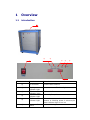
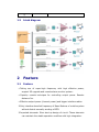
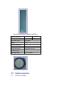
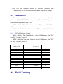
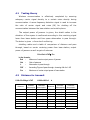
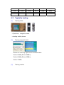
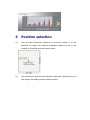
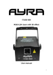
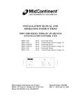
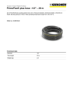
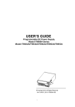
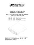
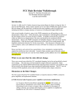
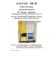
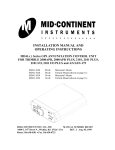
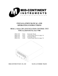
GSM/DCS/CDMA Jammer User Manual Version 1.1 August 24, 2007 VAF Corp. Data Communication Tell: 44655121 Fax: 44658496 TABLE OF CONTENT 1 2 OVERVIEW ......................................................................... 1 1.1 INTRODUCTION ...................................................................... 1 1.2 BLOCK DIAGRAM ..................................................................... 2 FEATURE ............................................................................ 2 2.1 FEATURE.............................................................................. 2 2.2 TECHNIQUE SPECIFICATIONS....................................................... 3 3 INSTALLATION ................................................................... 3 3.1 INSTALLATION MATERIAL ........................................................... 3 3.2 SYSTEM PREPARING ................................................................. 4 3.3 POWER CONTROL .................................................................... 6 4 FIELD TESTING .................................................................. 6 4.1 TESTING THEORY .................................................................... 7 4.2 DISTANCE FOR TRANSMIT .......................................................... 7 4.3 TYPICALLY TESTING ................................................................. 8 5 POSITION SELECTION ........................................................ 9 6 QUESTION AND ANSWER ................................................. 10 1 Overview 1.1 introduction ① ⑤ ⑤ ⑦ ④ ② ③ ⑥ Serial number Function Remark ① RF connector Connect with antenna ② Working Indicator Light 28Volt Power Indicatior Light 12Volt Power Indicator Light VSWR Alarm Indicator Light trun on or trun off indictor light ③ ④ ⑤ ⑥ Power Control Remote it is in mainframe it is ready for update When the antenna doesn’t connect with jammer or Working power is minmun,the alarm indicator light is turn on pls check following form ⑦ Power switcher 1.2 block diagram 2 Feature 2.1 Feature Taking use of super-high frequency with high effective power, support 3G upgrade and remote alarm monitor system. Capacity remote technique for controlling output power. Remote distance 3m. Effective output power (channel power) and bigger interfere radius. Only interfere downlink frequency of Base Stations of mobile system without disturb normally working of BTS. Imported elements: Slow start up design of circuit. These elements can maintain the stable operation condition with high integration. 2.2 Technique specifications Output Shield interface frequency band of 870-880MHz 900M 935-960MHz 1800M 1805-1850MHz 1895-1918MHz RF output power Output power/channel 50dBm 18dBm/30KHz(min) 48dBm 14dBm/30KHz(min) Power supply:AC220V-DC28V or DC5V Shielding area:100m-250m(It depends on field strength in given area) Power consumption: 680W or so; Net Weight:65KG or so; Gross Weight: 100 Kg Dimension of Jammer(L×W×H):600×600×800mm; Bamboo box (L*W*H):690*690*890mm 3 Installation 3.1 Installation material System should consist of : Remote control main package (shield package, AD/CD converter, power line), antenna connecter lines (cable and N connecters) Fixed part (1) Remote control (2) Antenna Directional antenna (900MHz/1900MHz) Band of frequency: 900MHz 1800MHz Gain: 12dBi 15dBi Half power beam: 65°H-plane VSWR: ≤ 1.5 Front to back ratio: 25 dB Magnetization type: Vertical length×wind×high: 1200×280×100 mm Connecter type: N Installation pillar: φ 50-φ 114mm (3) Connecter line 3.2 System preparing (1) Open the package Carefully open the package, keep all package boxes for later shipment. Check whether any part is damaged or not, if any damage happened, please contacting with your provider. (2) Connecter system Connecting the system, connecter lines are used to link the main package equipment with antennae by comparison of the top view. (The antennae must be firstly installed on the solid poles ) After connecting the system fittings, a power line is used to electrical outlet at the one end and the other end is put into power socket.(switching on is not allowed before the all antennae have been linked, otherwise the equipment is easy to be damaged. (3) Power on After all lines (include in bother connecter lines and power line)have been linked, turn on the switcher on the main machine. The output power of jammer is maximal in this situation. (4) Power off Turn off the switcher on the main machine, the jammer is out of work. Notices Be sure to connect all antenna first before the power supply is switch on. Please do not take off antennae when the machine is working. Antenna shall be used vertical to the ground, working more efficiently. Please don’t put the jammer in the water and fire to avoid using in the bad condition of over-wet, over-hot, high voltage and high magnetism. If the jammer can not be charged or other unconventionality( the indicator light doesn’t light up), please contact with the distributor in local place. Any refit and incorrect repair is not allowed. Any ruin and disrepair caused by incorrect operation and disassembly will be excluded from the repair with free of charge. 3.3 Power control There are four group switchers which are used to control RF output power for CDMA,GSM,DCS,PHS comparatively. Each is 31dB adjustable output power adjustable step is 1dB NO.1 to No.5 of Dial Code Switch is control DCS power, Dial “ON” is 1,Dial “number” port is 0 NO.6 to No.10 of Dial Code Switch is control PHS power, Dial “ON” is 1,Dial “number” port is 0 (1) CDMA/GSM Power Control NO.1 to No.5 of Dial Code Switch is control CDMA power, Dial “ON” is 1,Dial “number” port is 0 NO.6 to No.10 of Dial Code Switch is control GSM power, Dial “ON” is 1,Dial “number”port is 0 NO.1-No.5 or No.6-No.10 00000 00001 00010 00011 00100 00101 00110 00111 01000 01001 01010 01011 01100 01101 01110 01111 4 Power level 0 Min 1 2 3 4 5 6 7 8 9 10 11 12 13 14 15 Field Testing NO.1-No.5 or No.6-No.10 10000 10001 10010 10011 10100 10101 10110 10111 11000 11001 11010 11011 11100 11101 11110 11111 Power level 16 17 18 19 20 21 22 23 24 25 26 27 28 29 30 31 Max 4.1 Testing theory Wireless communication is effectively completed by ensuring adequacy carrier signal density to a certain noise density during communication. A same frequency distortion signal is used to increase the ratio of carrier signal and noise (Nf) for shutting off the communication between the base station and mobile phone. The output power of jammer is given, the shield radius in the situation of free space is confirmed according to the receiving signal lever from base station and free space attenuation in pass through. The below is given a formula of confirming shielding radius and a table of comparison of distance and pass through, based on carrier receiving power from base station, output power of jammer as well as gain of antenna: Pch+Gat-L+FAF≥ Prx In the formula: 4.2 Pch Gat L FAF : : : : Minimum of carrier output power of jammer Gain of antenna Attenuation in pass through Amending Figure of pass through, choosing 6db for 1.8G Prx : Maximum of carrier output power of base station Distance for transmit L900=32+20logd +FAF L1800=L900+6 d distance 900MHz attenuation 1800MHz attenuation distance 900MHz attenuation 1800MHz attenuation 1m 38 dB 44 dB 25 m 70 dB 76 dB 2m 44 dB 50 dB 30 m 72 dB 78 dB 3m 50 dB 56 dB 35 m 74 dB 80 dB 4m 54 dB 60 dB 40 m 75 dB 81 dB 5m 56 dB 62 dB 45 m 76 dB 82 dB 6m 58 dB 64 dB 50 m 77 dB 83 dB 7m 60 dB 66 dB 60 m 78 dB 84 dB 8m 61 dB 67 dB 70 m 80 dB 86 dB 9m 62 dB 68 dB 80 m 81 dB 87 dB 10 m 63 dB 69 dB 90 m 82 dB 88 dB 15 m 64 dB 70 dB 100 m 82 dB 89 dB 20 m 68 dB 74 dB 200 m 84 dB 90 dB 4.3 Typically testing (1) Testing tools: Spectrum、magnetic meter testing mobile phone (2) Testing magnetic field Maximum receiving signal level from base station: RxLev-50dBm,RxLev-55dBm, RxLev-60dBm,RxLev-65dBm, RxLev-70dBm. (3) Testing results: 5 Position selection (1) Use all omni-directional antenna (in common sense, it is not approve of using) the transmit antennae should be put in the middle of shielding area as below shown. (2) Use directional antenna the transmit antennae should be put at the edges of shielding area as below shown. 6 Question and answer (1) Will jammer interfere the other electronic equipment to work in normal condition? No. Because the electromagnetic signal sent by jammer are totally used in the band that regulated by government and just have interception effect to cell phone communication. (2) Is jammer harmful to the human body and cell phone? Please do not need to worry about it. The intensity of electromagnetic signal sent by jammer is in compliance with the national standard of environmental electromagnetic wave health. The signal sent by jammer is relatively small and unharmful to human body according to the testing result. Meanwhile, this device just damage the receiving condition to the cell phone and makes the normal connection between cell phone and base station impossible. Therefore, no damage will occur on cell phone itself. (3) Is there any difference of distance between using jammer indoor and outdoor? Yes. Generally speaking, outdoor signal is bigger than the indoor signal. Thereby, the shielding effect is worse outdoor. Strictly speaking, whether using indoor or outdoor, the effective distance of interference is related to the surrounding around, for example the distance between different base stations, positions of installation etc. (4) Is the jammer has the same effect to GSM cell phone and CDMA cell phone? The capacity of anti-interference of CDMA is much better than GSM cell phone. So the interference effect for GSM cell phone is better than CDMA cell phone. (5) The shell of jammer will become hot after working for some times. Does the long working time will damage the machine itself? It is very normal. When designing, we are thinking of taking use of the conductivity of metal shell to help the heat sinking during our designation. By this way, the machine can be kept in good working condition for long time.