1
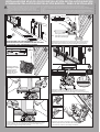
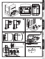
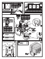
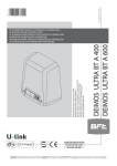
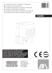
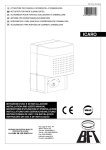
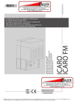
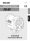
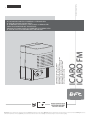
027908
D811310 00100_03 17-07-12
8
412638
ICARO
ICARO FM
ISTRUZIONI D’USO E DI INSTALLAZIONE
INSTALLATION AND USER’S MANUAL
INSTRUCTIONS D’UTILISATION ET D’INSTALLATION
INSTALLATIONS-UND GEBRAUCHSANLEITUNG
INSTRUCCIONES DE USO Y DE INSTALACION
INSTALLATIEVOORSCHRIFTEN
ATTUATORE PER CANCELLI SCORREVOLI A CREMAGLIERA
ACTUATOR FOR RACK SLIDING GATES
ACTIONNEUR POUR PORTAILS COULISSANTS A CREMAILLERE
TRIEB FÜR SCHIEBETORE MIT ZAHNSTANGE
SERVOMOTOR PARA CANCELAS CORREDERAS DE CREMALLERA
ACTUATOR VOOR SCHUIFHEKKEN MET TANDHEUGEL
Attenzione! Leggere attentamente le “Avvertenze” all’interno! Caution! Read “Warnings” inside carefully! Attention! Veuillez lire attentivement les Avertissements qui se trouvent à l’intérieur! Achtung! Bitte lesen Sie
aufmerksam die „Hinweise“ im Inneren! ¡Atención¡ Leer atentamente las “Advertencias” en el interior! Let op! Lees de “Waarschuwingen” aan de binnenkant zorgvuldig!
a) Prima di iniziare con l’installazione bisogna leggere le avvertenze.
a) Before commencing installation, make sure you read the warnings.
a) Avant de commencer l’installation lisez les avertissements.
a) Vor der Installation müssen die Hinweise gelesen werden.
a) Antes de comenzar con la instalación es necesario leer las advertencias.
a) Voor met de installatie te beginnen moet u de waarschuwingen lezen.
b) Oltre alle figure, bisogna seguire le indicazioni date nel paragrafo corrispondente a pag.6
b) In addition to the figures, you must follow the instructions given in the relevant section on page 6
b) Suivez non seulement les figures mais aussi les indications données dans le paragraphe correspondant à
la page 6
b) Außer den Abbildungen müssen die Angaben im entsprechenden Abschnitt auf Seite 6 befolgt werden
b) Además de las figuras, es necesario seguir las indicaciones dadas en el apartado correspondiente en pág. 6
b) Volg niet alleen de figuren, maar ook de aanwijzingen die in de paragraaf op pag. 6 staan
A
B
> 29mm
2
m
5x0
,5m
3x1
.5m
2x0.5mm2
3x0.5mm2
m2
Cremallera, Tandheugel
2x1.5mm2
RG58
3x1.5mm2
20mm + “ X”
Predisposizione fissaggio motore, Preparation for motor mounting,
Aménagement fixation moteur, Vorbereitung Motorbefestigung,
Disposición fijación del motor, Voorbereiding bevestiging motor.
PREDISPOSIZIONE TUBI, TUBE ARRANGEMENT,
PRÉDISPOSITION DES TUYAUX, VORBEREITUNG DER LEITUNGEN,
DISPOSICIÓN DE TUBOS, VOORBEREIDING LEIDINGEN.
> 10mm
Cremagliera, Rack,
“X” Crémaillère, Zahnstange,
C
D
Y
Montaggio motore,
Mounting the motor,
Montage moteur,
Montage Motor,
Montaje del motor,
Montage motor.
D1
Y
E
Montaggio accessori trasmissione, Mounting drive accessories,
Montage accessoires transmission, Montage Antriebszubehör,
Montaje de accesorios transmisión, Montage accessoires overbrenging.
F
Fissaggio staffe finecorsa (dx e sx), Fastening limit switch brackets (RH/LH),
Fixation étriers fin de course (drt et gch), Befestigung Bügel Anschläge
(rechts und links), Fijación abrazaderas final de carrera (der. e izq.),
Bevestiging stangen aanslag (rechts en links).
2 -
ICARO - ICARO FM
Collegamento morsettiera, Terminal board wiring,
Connexion plaque à bornes, Anschluss Klemmleiste,
Conexión tablero de bornes, Aansluiting aansluitkast.
D811310 00100_03
INSTALLAZIONE VELOCE-QUICK INSTALLATION-INSTALLATION RAPIDE
SCHNELLINSTALLATION-INSTALACIÓN RÁPIDA - SNELLE INSTALLATIE
D811310 00100_03
ITALIANO
G
178
11
60
107
22
226
16
57.5
16
21.5
40
376
35
R 20
55
168
65
35
152
270
226
212.5
00
p1 2
p7
5
Z2 8 Ø
Z1
Ø
21.5
ENGLISH
22
217
10.75
10.75
260
0
26
40
260
31.5
90
56.5
R 20
22
100
160
I
J
K
22
30
H
FRANÇAIS
12
22
37
28
CFZ
CVZ
2mm
K1
Min. 94w mm
Min. 141 mm (Z25)
ESPAÑOL
L
centro pignone - center pinion
le pignon de centre - ritzelachse
centro pinon-het centrum rondsel
20
ICARO - ICARO FM -
3
NEDERLANDS
Min. 127 mm (Z18)
DEUTSCH
OK
NO
10 11 12 13
MB N
c
P3
M
M
MARRONE
BROWN
MARRON
BRAUN
MARRÓN
BRUIN
N
Min. 50mm
B
BLU
BLUE
BLEU
BLAU
AZUL
BLAUW
N
NERO
BLACK
NOIR
SCHWARZ
NEGRO
ZWART
O
P1
***
*
**
V2
41 42 43
*
**
***
ROSSO
RED
ROUGE
ROT
ROJO
ROOD
MARRONE
BROWN
MARRON
BRAUN
MARON
BRUIN
NERO
BLACK
NOIR
NERO
NEGRO
ZWART
GND
A
V1
3,5 mm
V1
A
13 mm
P2
3,5 mm
V2
JP1
L
N GND
16 mm
D
P
V3
Q
4 mm
SOLO PER ICARO FM: / FOR ICARO ONLY:
UNIQUEMENT POUR ICARO FM: / NUR FÜR ICARO FM:
SÓLO PARA ICARO FM: / ALLEEN VOOR ICARO FM:
12 mm
13
17
A
+
V3
4 -
ICARO - ICARO FM
D811310 00100_03
M
D811310 00100_03
INSTALLER WARNINGS
WARNING! Important safety instructions. Carefully read and comply with
all the warnings and instructions that come with the product as incorrect
installation can cause injury to people and animals and damage to property.
The warnings and instructions give important information regarding safety,
installation, use and maintenance. Keep hold of instructions so that you can
attach them to the technical file and keep them handy for future reference.
ENGLISH
GENERAL SAFETY
This product has been designed and built solely for the purpose indicated herein.
Uses other than those indicated herein might cause damage to the product and
create a hazard.
- The units making up the machine and its installation must meet the requirements
of the following European Directives, where applicable: 2004/108/EC, 2006/95/
EC, 2006/42/EC, 89/106/EC, 99/05/EC and later amendments. For all countries
outside the EEC, it is advisable to comply with the standards mentioned, in addition to any national standards in force, to achieve a good level of safety.
- The Manufacturer of this product (hereinafter referred to as the “Firm”) disclaims
all responsibility resulting from improper use or any use other than that for
which the product has been designed, as indicated herein, as well as for failure
to apply Good Practice in the construction of entry systems (doors, gates, etc.)
and for deformation that could occur during use.
- Before installing the product, make all structural changes required to produce
safety gaps and to provide protection from or isolate all crushing, shearing and
dragging hazard areas and danger zones in general in accordance with the
provisions of standards EN 12604 and 12453 or any local installation standards.
Check that the existing structure meets the necessary strength and stability
requirements.
- Before commencing installation, check the product for damage.
- The Firm is not responsible for failure to apply Good Practice in the construction
and maintenance of the doors, gates, etc. to be motorized, or for deformation
that might occur during use.
- Make sure the stated temperature range is compatible with the site in which the
automated system is due to be installed.
- Do not install this product in an explosive atmosphere: the presence of flammable
fumes or gas constitutes a serious safety hazard.
- Disconnect the electricity supply before performing any work on the system.
Also disconnect buffer batteries, if any are connected.
- Before connecting the power supply, make sure the product’s ratings match the
mains ratings and that a suitable residual current circuit breaker and overcurrent
protection device have been installed upline from the electrical system. Have
the automated system’s mains power supply fitted with a switch or omnipolar
thermal-magnetic circuit breaker with a contact separation that meets code
requirements.
- Make sure that upline from the mains power supply there is a residual current
circuit breaker that trips at no more than 0.03A as well as any other equipment
required by code.
- Make sure the earth system has been installed correctly: earth all the metal parts
belonging to the entry system (doors, gates, etc.) and all parts of the system
featuring an earth terminal.
- Installation must be carried out using safety devices and controls that meet
standards EN 12978 and EN 12453.
- Impact forces can be reduced by using deformable edges.
- In the event impact forces exceed the values laid down by the relevant standards,
apply electro-sensitive or pressure-sensitive devices.
- Apply all safety devices (photocells, safety edges, etc.) required to keep the
area free of impact, crushing, dragging and shearing hazards. Bear in mind the
standards and directives in force, Good Practice criteria, intended use, the installation environment, the operating logic of the system and forces generated by
the automated system.
- Apply all signs required by current code to identify hazardous areas (residual
risks). All installations must be visibly identified in compliance with the provisions
of standard EN 13241-1.
- Once installation is complete, apply a nameplate featuring the door/gate’s data.
- This product cannot be installed on leaves incorporating doors (unless the motor
can be activated only when the door is closed).
- If the automated system is installed at a height of less than 2.5 m or is accessible,
the electrical and mechanical parts must be suitably protected.
- Install any fixed controls in a position where they will not cause a hazard, away
from moving parts. More specifically, hold-to-run controls must be positioned
within direct sight of the part being controlled and, unless they are key operated,
must be installed at a height of at least 1.5 m and in a place where they cannot
be reached by the public.
- Apply at least one warning light (flashing light) in a visible position, and also
attach a Warning sign to the structure.
- Attach a label near the operating device, in a permanent fashion, with information on how to operate the automated system’s manual release.
- Make sure that, during operation, mechanical risks are avoided or relevant
protective measures taken and, more specifically, that nothing can be banged,
crushed, caught or cut between the part being operated and surrounding parts.
- Once installation is complete, make sure the motor automation settings are
correct and that the safety and release systems are working properly.
- Only use original spare parts for any maintenance or repair work. The Firm disclaims all responsibility for the correct operation and safety of the automated
system if parts from other manufacturers are used.
- Do not make any modifications to the automated system’s components unless
explicitly authorized by the Firm.
- Instruct the system’s user on what residual risks may be encountered, on the
control systems that have been applied and on how to open the system manually in an emergency. give the user guide to the end user.
- Dispose of packaging materials (plastic, cardboard, polystyrene, etc.) in accordance with the provisions of the laws in force. Keep nylon bags and polystyrene
out of reach of children.
WIRING
WARNING! For connection to the mains power supply, use: a multicore cable with
a cross-sectional area of at least 5x1.5mm2 or 4x1.5mm2 when dealing with threephase power supplies or 3x1.5mm2 for single-phase supplies (by way of example,
type H05 VV-F cable can be used with a cross-sectional area of 4x1.5mm2). To connect auxiliary equipment, use wires with a cross-sectional area of at least 0.5 mm2.
- Only use pushbuttons with a capacity of 10A-250V or more.
- Wires must be secured with additional fastening near the terminals (for example,
using cable clamps) in order to keep live parts well separated from safety extra
low voltage parts.
- During installation, the power cable must be stripped to allow the earth wire
to be connected to the relevant terminal, while leaving the live wires as short
as possible. The earth wire must be the last to be pulled taut in the event the
cable’s fastening device comes loose.
WARNING! safety extra low voltage wires must be kept physically separate from
low voltage wires.
Only qualified personnel (professional installer) should be allowed to access
live parts.
CHECKING THE AUTOMATED SYSTEM AND MAINTENANCE
Before the automated system is finally put into operation, and during maintenance
work, perform the following checks meticulously:
- Make sure all components are fastened securely.
- Check starting and stopping operations in the case of manual control.
- Check the logic for normal or personalized operation.
- For sliding gates only: check that the rack and pinion mesh correctly with 2 mm
of play along the full length of the rack; keep the track the gate slides on clean
and free of debris at all times.
- For sliding gates and doors only: make sure the gate’s running track is straight
and horizontal and that the wheels are strong enough to take the weight of the
gate.
- For cantilever sliding gates only: make sure there is no dipping or swinging
during operation.
- For swing gates only: make sure the leaves’ axis of rotation is perfectly vertical.
- Check that all safety devices (photocells, safety edges, etc.) are working properly
and that the anti-crush safety device is set correctly, making sure that the force
of impact measured at the points provided for by standard EN 12445 is lower
than the value laid down by standard EN 12453.
- Impact forces can be reduced by using deformable edges.
- Make sure that the emergency operation works, where this feature is provided.
- Check opening and closing operations with the control devices applied.
- Check that electrical connections and cabling are intact, making extra sure that
insulating sheaths and cable glands are undamaged.
- While performing maintenance, clean the photocells’ optics.
- When the automated system is out of service for any length of time, activate the
emergency release (see “EMERGENCY OPERATION” section) so that the operated
part is made idle, thus allowing the gate to be opened and closed manually.
- If the power cord is damaged, it must be replaced by the manufacturer or their
technical assistance department or other such qualified person to avoid any risk .
- If “D” type devices are installed (as defined by EN12453), connect in unverified
mode, foresee mandatory maintenance at least every six months
WARNING!
Remember that the drive is designed to make the gate/door easier to use and
will not solve problems as a result of defective or poorly performed installation
or lack of maintenance
SCRAPPING
Materials must be disposed of in accordance with the regulations in force. There
are no particular hazards or risks involved in scrapping the automated system. For
the purpose of recycling, it is best to separate dismantled parts into like materials
(electrical parts - copper - aluminium - plastic - etc.).
DISMANTLING
If the automated system is being dismantled in order to be reassembled at another
site, you are required to:
- Cut off the power and disconnect the whole electrical system.
- Remove the actuator from the base it is mounted on.
- Remove all the installation’s components.
- See to the replacement of any components that cannot be removed or happen
to be damaged.
Anything that is not explicitly provided for in the installation manual is not allowed. The operator’s proper operation can only be
guaranteed if the information given is complied with. The Firm shall
not be answerable for damage caused by failure to comply with the
instructions featured herein.
While we will not alter the product’s essential features, the Firm reserves the right, at any time, to make those changes deemed opportune to improve the product from a technical, design or commercial
point of view, and will not be required to update this publication
accordingly.
AVVERTENZE PER L’INSTALLATORE D811766_06
ICARO - ICARO FM -
7
1) FOREWORD
The ICARO/ICARO FM actuator offers ample installation versatility,
thanks to the extremely low position of the pinion, the compactness
of the actuator and to the height and depth which can be very easily
adjusted. It is equipped with an clutch unit between motor shaft and
worm screw in an oil bath to guarantee greater safety. The emergency
manual release can be activated very easily by means of a knob featuring
a personalised key.
The gate stop is controlled by electromechanical end-of-stroke
microswitches or, for very cold areas, by proximity sensors.
The control board can be built-in or installed onto a separate cabinet.
“Installation must be carried out by qualified personnel (professional
installer, according to EN 12635), in compliance with Good Practice
and current code”
2) TECHNICAL SPECIFICATIONS
MOTOR
Power supply
220-230V 50/60 Hz (*)
Motor
220-230V 50/60 Hz (*)
Power input
750W
Pinion module
4 mm 18 or 25 teeth
Leaf speed
Max. leaf weight
9m/min (18 teet) /12m/min (25 teeth)
with pinion Z18 20.000 N( ≈2000 kg)
FOR ICARO FM ONLY:
with pinion Z25 10.000 N( ≈1000 kg)
40Nm
Impact reaction
ICARO: Obstacle detection device
(Encoder)
ICARO FM: Clutch unit
ERGOIL
Manual operation
Knob-operated mechanical release
Type of use
intensive
Environmental conditions
from -15°C to +60°C
Protection rating
IP55
Noise level
<70dBA
Operator weight
25 kg
Dimensions
See Fig. G
(*) Special supply voltages to order.
3) TUBE ARRANGEMENT Fig.A
Install the electrical system referring to the standards in force for electrical
systems CEI 64-8, IEC 364, harmonization document HD 384 and other
national standards.
4) PREPARATION FOR MOTOR MOUNTING FIG.B
t .BLFBIPMFJOUIFHSPVOEUPBDDPNNPEBUFUIFDPODSFUFQBEXJUI
anchors embedded in the base plate for fastening the gearbox
assembly, keeping to the distances featured in FIG.B.
t 5PLFFQUIFCBTFQMBUFJOUIFSJHIUQPTJUJPOEVSJOHJOTUBMMBUJPOJUNBZ
be useful to weld two iron plates under the track to which the anchors
can then be welded (FIG.I).
5) MOUNTING THE MOTOR FIG.C
6) MOUNTING DRIVE ACCESSORIES FIG.D-D1
7) RACK CENTRING WITH RESPECT TO PINION FIG.J-K1-L
DANGER - Welding must be performed by a competent person
issued with the necessary personal protective equipment as
prescribed by the safety rules in force FIG.K.
8) FASTENING LIMIT SWITCH BRACKETS FIG.E
The runners must lock the gate before this intercepts the mechanical
backstops placed on the track. The closing end-of-stroke runner
adjustment must be made in such a way as to leave a clearance of
approximately 50mm between the gate and the fixed swing leaf, as
prescribed by the current safety standards, otherwise fit an electric
edge at least 50mm thick FIG.N.
8 -
ICARO - ICARO FM
10) MANUAL RELEASE (See USER GUIDE -FIG.2-).
Warning Do not JERK the gate open and closed, instead push it
GENTLY to the end of its travel.
---------------------------------------------------------11) TERMINAL BOARD WIRING Fig. F
Once suitable electric cables have been run through the raceways and
the automated device’s various components have been fastened at the
predetermined points, the next step is to connect them as directed and
illustrated in the diagrams contained in the relevant instruction manuals.
Connect the live, neutral and earth wire (compulsory). The mains cable
must be clamped in the relevant cable gland (FIG.O-ref.P1), and the
accessories’ wires in the cable gland (FIG.O-ref.P2), while the earth
wire with the yellow/green-coloured sheath must be connected in the
relevant terminal (FIG.O-ref.GND).
FIG.O-ref.P3: limit switch wiring.
WARNING! The ICARO actuator does not feature mechanical safety
clutch adjustment, making it essential to use a control panel with the
electronic torque control feature.
Max. torque
Lubrication
9) STOPS FIG.M
DANGER - The gate must be fitted with mechanical stops to halt
its travel both when opening and closing, thus preventing the
gate from coming off the top guide. Said stops must be fastened
firmly to the ground, a few centimetres beyond the electric stop point.
WARNING! The ICARO FM actuator features mechanical safety
clutch adjustment, making it essential to disable the encoder function.
12) ADJUSTMENT OF SAFETY CLUTCH FIG. P
Loading of clutch:
Keep the motor shaft still with the special spanner (CH 17), and tighten
the nut located on top of the loading spring (CH 13).
Release of the clutch:
Carry out the same operation as above but turn the nut (CH 13)
counterclokwise.
Make sure the operating force is not too low, so as to avoid useless stops
of the gate due to deposits on the rail. However it is important to observe
the anti-squash safety limits regulations.
13) SEE THE CONTROL UNIT’S USER GUIDE FOR
INFORMATION ON SETTINGTHE MOTOR’S PARAMETERS
14) FASTENING THE COVER Fig. Q
D811310 00100_03
INSTALLATION MANUAL