1
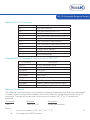
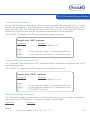
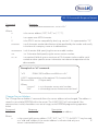
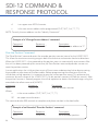
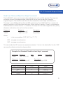
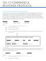
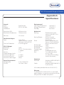
OWNERS MANUAL
V2.1
WATERLOG H-3301/3311
INCREMENTAL SHAFT ENCODER WITH SDI-12 AND QUADRATURE OUTPUTS
D34 0514
CONTENTS & WARRANTY
This user manual is a guide for the H-3301/3311 shaft encoder. For more information, updated
manuals, brochures, technical notes, and supporting software on the H-3301/H-3311 shaft encoder,
please refer to waterlog.com or contact your sales representative.
For additional assistance, please contact us at +1.435.753.2212 or [email protected]
WaterLOG® Warranty..................................................................1
Chapter 1: Introduction...............................................................2
Operation.................................................................................... 3
Programming the Data Recorder............................................. 4
Programming the H-3301/3311............................................... 4
Installation................................................................................... 5
Making Output Connections.................................................... 5
Words of Caution....................................................................... 6
Testing......................................................................................... 6
Chapter 2: H-3311 LCD Display................................................7
Overview..................................................................................... 8
Read Button Operation............................................................. 8
Using the Adjust Knob to Change Current Stage Value....... 8
Using the Adjust Knob to Change SDI-12 Address............... 8
Chapter 3: SDI-12 Command and Response Protocol.........9
Standard SDI-12 Commands.................................................. 11
Extended SDI-12 Commands Unique to H-3301/3311.......11
Measure Command..................................................................11
Measure Command with CRC.................................................12
Concurrent Measurement Command....................................13
Concurrent Measurement Command with CRC...................13
Send Data Command.............................................................. 14
Continuous Measurements..................................................... 15
Continuous Measurements with CRC.................................... 15
Send Acknowledge Command.............................................. 15
Initiate Verify Command.......................................................... 16
Send Identification Command................................................16
Change Sensor Address.......................................................... 17
Zero the Position Command................................................... 18
Read User Offset and Read User Slope Commands........... 19
Write User Offset and Write User Slope Commands.......... 20
Test Display............................................................................... 20
Appendix A: Specifications..................................................... 21
Contents & Warranty
“WATERLOG™ PRODUCTS MANUFACTURED BY YELLOW SPRINGS INSTRUMENTS CO., INC. are
warranted by Yellow Springs Instruments Co., Inc. (“YSI”) to be free from defects in materials and
workmanship under normal use and service for twelve (12) months from date of shipment unless
otherwise specified in the corresponding YSI pricelist or product manual.
WaterLOG™ products not manufactured, but that are re-sold by YSI, are warranted only to the
limits extended by the original manufacturer. Batteries, desiccant, and other consumables have
no warranty. YSI’s obligation under this warranty is limited to repairing or replacing (YSI’s option)
defective products,which shall be the sole and exclusive remedy under this warranty.
The customer shall assume all costs of removing, reinstalling, and shipping defective products to YSI.
YSI will return such products by surface carrier prepaid within the continental United States of America.
To all other locations, YSI will return such products best way CIP (Port of Entry) INCOTERM® 2010,
prepaid. This warranty shall not apply to any products which have been subjected to modification,
misuse, neglect, improper service, accidents of nature, or shipping damage. This warranty is in lieu
of all other warranties, expressed or implied. The warranty for installation services performed by YSI
such as programming to customer specifications, electrical connections to products manufactured by
YSI, and product specific training, is part of YSI’s product warranty. YSI EXPRESSLY DISCLAIMS AND
EXCLUDES ANY IMPLIED WARRANTIES OF MERCHANTABILITY OR FITNESS FOR A PARTICULAR
PURPOSE. YSI is not liable for any special, indirect, incidental, and/or consequential damages.”
A complete TERMS AND CONDITIONS OF SALE can be viewed at:
http://www.ysi.com/terms-and-conditions.php
1
01 /
2
INTRODUCTION
Introduction
The WaterLOG® H-3301/3311 is a digital shaft encoder which measures water depth by
monitoring the position of a float and pulley. The H-3311 has the same functionality as the H-3301
with the addition of a built-in display and manual offset adjustment feature making it easier to setup
and use in the field. See Chapter-2 for details concerning the LCD display and offset adjust control.
The H-3301/3311 is easy to use and works with any SDI-12 data recorder. For older loggers,
ALERT systems and the weather service LARK, the H-3301/3311 has a quadrature output that is
equivalent to the Handar 436A type shaft encoder. The “Serial-Digital Interface” is ideal for data
logging applications with the following requirements:
• Battery powered operation with minimal current drain
• Low system cost
• Multiple sensors on a simple three wire cable
• Up to 250 feet of cable between a sensor and the data recorder (Use of H-423, SDI-12 to RS485
converter extends the range to 1000’s of feet)
The H-3301/3311 has the following features:
• Scales the encoder position into user units of feet, meters, etc.
• Precision dual bearing design with special low temperature lubricant
• Threaded shaft compatible with older mechanical shaft encoders
• Zero backlash
• 200 counts per revolution for the SDI-12 output
• Sealed enclosure protects from moisture and dirt
• Low current operation (less than 2 milliamps)
• High speed encoder circuitry prevents missing counts due to rapid float movement from
wave action or sudden movement in freeze/thaw conditions - 15 ft/sec typical
• Water resistant connectors provide easy hookup
The LCD display on the H-3311 provides the following additional features:
• Continuous display readout always shows last measured value
• ‘Read’ button causes the H-3311 to continuously update the display while the button is pressed
• The adjust knob allows the user to manually set the stage
• The adjust knob allows the user to manually set the sensor SDI-12 address
Operation
The H-3301/3311 is a precision shaft encoder with a resolution of two hundred counts per revolution
(0.005 ft with a 1 ft circumference pulley). The H-3301/3311 has an internal microprocessor controlled
digital counter which monitors two digital outputs from a shaft position sensor. The sensor generates
quadrature pulses and phase information. The phase information indicates which direction the shaft
is turning. The H-3301/3311 continuously maintains a digital count representing the current position
of the shaft. The H-3301/3311 counts to ±32,768 steps.
During normal operation, the SDI-12 data recorder sends an address followed by a measurement
command to the H-3301/3311 sensor. The H-3301/3311 wakes up from its low power sleep mode,
3
converts the shaft position into Feet, Meters or other units programmed for the stage
measurement and stores this data in its data buffer. Once the data is ready, the data recorder
collects the data from the H-3301/3311’s data buffer.
INTRODUCTION
Programming The Data Recorder
You must prepare your data recorder to receive and record the H-3301/3311 data. Since data
recorders differ widely, refer to your recorder manufacturer’s directions. The H-3301/3311
maintains two values or parameters about the shaft position: the Stage in the selected engineering
units and the Absolute Shaft Position in single unit steps. In general, program your data recorder
to record one or two values from the H-3301/3311 via the SDI-12 port. Usually only the first value
is recorded. The data recorder must issue an “aM!” command, then collect the data with a “aD0”
command, as explained in Chapter 3. The H-3301/3311 places two data values in its data buffer:
a±XX.XX±NNNN
Where:
a XX.XX
NNNN Is the the SDI-12 address 0-9, A-Z
Is the current encoder position (Stage) in user units (Feet, Meters etc.)
Is the current absolute encoder position in units of steps (raw counts)
Programming The H-3301/3311
The H-3301/3311 comes from the factory with the following settings:
SDI Address: 0
Slope: 0.0050
Offset: 0.000
With these values Stage will be in units of feet when used with a pulley having a circumference
of 12 inches. The slope value can be changed to accommodate other pulley circumferences or to
change the data to other engineering units such as inches or Meters. The Address, Slope and
Offset setup is stored in EEPROM within the H-3301/3311 and will not be lost if the power is
disconnected. The extended commands for changing the slope, offset and sensor address are
described in detail in Chapter 3. If more than one sensor is to be connected to the SDI-12 bus,
make certain each sensor has a different sensor address.
Many applications use a shaft encoder to monitor water in a stilling well. A float and pulley
translate the water level to rotation of the encoder’s shaft. When the H-3301/3311 is installed,
the encoder will be at a position determined by the current water level. When the H-3301/3311 is
powered up it resets its internal position count to 0. All subsequent measurements will be
relative to this initial position. If a measurement in absolute units or stage is wanted, you will
need to change the OFFSET value to match the current stage as measured by a staff gauge or
other datum.
Incremental encoders such as a quadrature encoders, monitor CHANGES in shaft position. With
an incremental encoder, if the power is lost the encoder reference or zero position is also lost.
The position count is maintained in RAM (not EEPROM) within the H-3301/3311. Storing the
position in non-volatile (EEPROM) memory would not protect from power loss because encoder
position changes would be missed during the loss of power. The H-3301/3311 protects its
4
Introduction
position count with a software flag or “signature”. If the power is removed momentarily the
H-3301/3311 will resume operation using the current position count. If the power is lost long
enough to destroy the signature, when the power is restored the H-3301/3311 resets the position
count to 0000. To intentionally reset the H-3301/3311’s position count, disconnect the power for
5 to 10 seconds.
A backup battery input is also provided to maintain shaft position during main power interruption
or loss. Any shaft movements while main power is lost will still be recognized and when main
power is restored the measured values will reflect the shaft changes while main power was lost.
Without the backup battery the value would start again at 0.00 plus the current offset value.
With the shaft pointing toward you, rotating the encoder shaft counter-clockwise produces an
increasing (positive) shaft position value. If this is backwards from your needs, either program
the slope with a negative value for SDI-12 applications, or exchange the two quadrature
connections to the shaft encoder for quadrature applications.
Installation
The H-3310/3311 is suitable for outdoor environments but must be installed in a protective
enclosure or gauge house. Normally, the housing is screwed or bolted to a shelf in the gauge
station with the pulley and tape protruding over the edge of the shelf above the water. Make
certain the housing is level and the pulley and tape do not rub on any obstructions.
Making Output Connections
The H-3301/3311 has both a SDI-12 and quadrature outputs. The H-3301/3311 is an SDI-12
V1.3 compliant sensor. It connects directly to any data recorder with SDI-12 capability. In addition,
the H-3301/3311 provides a raw quadrature output for use with other data recorders having a
quadrature input.
The power for the H-3301/3311 is supplied by the SDI-12 +12V input. Table 1 shows the proper
connections. Refer to the wiring diagram printed on the side of the H-3301/3311 for the connector
pinout.
Table 1 Cable Connections
Pin
Wire
Name
A
Red
+12V DC
B
Black
Ground
C
Green
Ground
D
Yellow
SDI-12 Data
E
Orange
Quadrature Phase A
F
Brown
Quadrature Phase B
G
Blue
Battery Backup
5
INTRODUCTION
Words of Caution
• Make certain the encoder’s output does not go negative or more than +5.0 Volts
• Make certain the ground and power pins are connected to the encoder
• Keep the lead wires as short as possible
• Use shielded cables in noisy environments
Testing
After completing the installation, test the encoder by manually rotating the pulley. For the H-3311
press and hold the “Read” button to observe the display. Make certain the readout matches the
expected measurement. For the H-3301 make an SDI-12 measurement and check for the expected
measurement data.
6
02 /
H-3311 LCD DISPLAY
7
H-3311 LCD DISPLAY
Overview
The H-3311 has the same functionality as the H-3301 with the addition of a built in display and
manual offset adjustment. The LCD display shows the last measured value. The display uses ultra low
power and is always visible.
The offset adjustment is a rotary digital encoder and is accessed by removing the attached dust
cover. The adjustment encoder has a screwdriver slot and is easily rotated with a screwdriver or
other flat blade tool. Replace the dust cap whenever the adjustment is not being used.
Read Button Operation
The H-3311 has a ‘Read’ button that when pressed will cause the unit to continuously make
measurements and update the display. The display will flash when the unit is making continuous
measurements indicating the display is being updated even if the value is not changing. When
the button is released the display will freeze with the last measured value displayed. Measurement
requests from an attached SDI-12 data logger will also cause the display to update.
Using the Adjust Knob to Change Current Stage Value
While the ‘Read’ button is pressed, the Adjust screw may be turned to increase or decrease the
current stage value. With a positive slope rotating the adjustment screw clock-wise to increment
the value and counter-clock wise to decrement the value. Turning the Adjust screw slowly will
change the thousandths digit while turning the screw fast changes the tenths digit. This allows
one control to make both fine and course adjustments.
Using the Adjust Knob to Change SDI-12 Address
If the ‘Read’ button is held down while the H-3311 is being powered up, the display will show
the current SDI-12 address. The SDI-12 address may be changed using the Adjust screw.
Turning the Adjust screw will change the address in the range of 0 to 9. When the Read button is
released the new SDI-12 address is saved and the display switches to the normal stage readout.
To change the SDI-12 address again, the power must be disconnected and the special power-up
sequence repeated.
8
03 /
SDI-12 COMMAND &
RESPONSE PROTOCOL
9
SDI-12 COMMAND &
RESPONSE PROTOCOL
This is a brief description of the Serial Digital Interface (SDI-12) Command and Response
protocol used by the WATERLOG® Series Model H-3301/3311 sensor. Included is a description
of the commands and data format supported by the H-3301/3311.
Refer to the document “A SERIAL DIGITAL INTERFACE STANDARD FOR HYDROLOGIC AND
ENVIRONMENTAL SENSORS”. Version 1.3 January 12, 2009 Coordinated by the SDI-12 Support
Group.
During normal communication, the data recorder sends an address together with a command to
the H-3301/3311 sensor. The H-3301/3311 then replies with a “response”. In the following
descriptions, SDI-12 commands and responses are enclosed in quotes. The SDI-12 address and
the command/response terminators are defined as follows:
“a” Is the sensor address. The following ASCII Characters are valid addresses: “0-9”, “A-Z”, “a-z”, “*”, “?”. Sensors will be initially programmed at the factory with the address of
“0” for use in single sensor systems. Addresses “1 to 9” and “A to Z” or “a to z” can be
used for additional sensors connected to the same SDI-12 bus. Address “*” and “?” are
“wild card” addresses which select any sensor, regardless of its actual address.
“!” Is the last character of a command block.
“<cr><lf>
” Are carriage return (0D) hex and line feed (0A) hex characters. They are the last two characters of a response block.
Notes:
• All commands/responses are upper-case printable ASCII characters.
• Commands must be terminated with a “!” character.
• Responses are terminated with <cr><lf> characters.
• The command string must be transmitted in a contiguous block with no gaps of more than 1.66 milliseconds between characters.
To enhance the error detection capability in SDI-12 data collection systems, a variation of the Start
Measurement Commands (M!, M1! ... M9!), Start Concurrent Measurement Commands (C!, C1! ...
C9!), and Continuous Measurement Commands (aR0! ... aR9!) request that the data be returned
with a 16 bit Cyclic Redundancy Check (CRC) appended to it. These commands use the existing
command letters with a C appended, namely: aMC!, aMC1! ... aMC9!, aCC!, aCC1! ... aCC9!, and
aRC0! ... aRC9!. When these commands are used, the data returned in response to the D commands,
or R commands, have a CRC code appended to it.
10
SDI-12 Command & Response Protocol
Standard SDI-12 Commands
Command
aM!
aMC!
aC!
aCC!
aD0!
aR0!
aRC0!
aV!
aAn!
al!
a!
Description
Make Measurement
Make Measurement with CRC
Make Concurrent Measurement
Make Concurrent Measurement with CRC
Send Data
Make Continuous Measurement
Make Continuous Measurement with CRC
Verify Sensor
Change Sensor Address
Send Identification
Send Acknowledge
Extended SDI-12 Commands Unique to the H-3301/3311
Command
aXHELP!
aXRS!
aXWSddd!
aXRO!
aXWOddd!
aXZ!
aXTD!
aXSDddd!
aXTEST!
Description
Print a Command Listing
Read Slope
Write Slope
Read Offset
Write Offset
Zero the Position
Run a Check on the Display
Output a Specific Value to the Display
Initiate a Repeating Test Printout
Measure Command
The “Measure” command causes a measurement sequence to be performed. Data values generated
in response to this command are stored in the sensor’s buffer for subsequent collection using “D”
commands. The data will be retained in the sensor until another “M”, “C” or “V” command is
executed.
Command “aM!”
Response “atttn<cr><lf>”
Description
Initiate measurement
Where:
a
is the sensor address (“0-9”, “A-Z”, “a-z”, “*”, “?”).
is an upper-case ASCII character
M
11
SDI-12 COMMAND &
RESPONSE PROTOCOL
ttt n
is a three digit integer (000-999) specifying the maximum time, in seconds, the sensor
will take to complete the command and have measurement data available in its buffer.
is a single digit integer (0-9) specifying the number of values that will be placed in the
data buffer. If “n” is zero (0), no data will be available using subsequent “D” commands.
Upon completion of the measurement, a service request “a<cr><lf>” is sent to the data recorder
indicating the sensor data is ready. The data recorder may wake the sensor with a break and collect
the data anytime after the service request is received or the specified processing time has elapsed.
Example of an ‘aM!’ Command:
Command Response Time ‘aM!’
“a0012<cr><lf>” 1 sec Values
2 Description
Return encoder position
Subsequent Command
Response
“aD0” a+X.XX+NNNN<cr><lf>
Where:
X.XX NNNN = Current position (stage), in user programmable units
= Current position, in raw position counts
Measure Command with CRC
This “Measure” command causes a measurement sequence to be performed with a CRC appended
to the data. Data values generated in response to this command are stored in the sensor’s buffer
for subsequent collection using “D” commands. The data will be retained in the sensor until
another “M”, “C” or “V” command is executed.
Command “aMC!” Response “atttn<cr><lf>” Description
Initiate measurement
Where:
a
is the sensor address (“0-9”, “A-Z”, “a-z”, “*”, “?”).
is an upper-case ASCII character
M
ttt is a three digit integer (000-999) specifying the maximum time, in seconds, the sensor will take to complete the command and have measurement data available in its buffer.
n
is a single digit integer (0-9) specifying the number of values that will be placed in the data buffer. If “n” is zero (0), no data will be available using subsequent “D” commands
Upon completion of the measurement, a service request “a<cr><lf>” is sent to the data recorder
indicating the sensor data is ready. The data recorder may wake the sensor with a break and
12 collect the data anytime after the service request is received or the specified processing time has
elapsed.
SDI-12 Command & Response Protocol
Example of an ‘aM!’ Command:
Command Response Time ‘aMC!’
“a0012<cr><lf>” 1 sec Values
2 Description
Return encoder position
Subsequent Command
Response
“aD0” a+X.XX+NNNN<cr><lf>
Where:
X.XX NNNN YYY = Current position (stage), in user programmable units
= Current position, in raw position counts
= CRC (ASCII Characters)
Concurrent Measurement Command
A “Concurrent Measurement” is one which occurs while other SDI-12 sensors on the bus are also
taking measurements. This command is similar to the “aM!” command, however, the nn field has
an extra digit and the sensor does not issue a service request when it has completed the measurement.
Communicating with other sensors will NOT abort a concurrent measurement. Data values generated
in response to this command are stored in the sensor’s buffer for subsequent collection using “D”
commands. The data will be retained in the sensor until another “M”, “C” or “V” command is executed.
Command “aC!”
Response “atttnn<cr><lf>”
Description
Initiate measurement
Where:
a
is the sensor address (“0-9”, “A-Z”, “a-z”, “*”, “?”).
is an upper-case ASCII character
C
ttt is a three digit integer (000-999) specifying the maximum time, in seconds, the sensor will take to complete the command and have measurement data available in its buffer.
nn is a two digit integer (00-99) specifying the number of values that will be placed in the data buffer. If “n” is zero (0), no data will be available using subsequent “D” commands.
The data recorder may wake the sensor with a break and collect the data anytime after the specified
processing time has elapsed.
Concurrent Measurement Command with CRC
The “Concurrent Measure with CRC” command causes a measurement sequence to be performed
with a CRC appended to the data. Data values generated in response to this command are stored
in the sensor’s buffer for subsequent collection using “D” commands. The data will be retained in
the sensor until another “M”, “C” or “V” command is executed.
Command “aCC!”
Response “atttnn<cr><lf>”
Description
Initiate measurement
13
SDI-12 COMMAND &
RESPONSE PROTOCOL
Where:
a
C
is the sensor address (“0-9”, “A-Z”, “a-z”, “*”, “?”).
is an upper-case ASCII character
ttt is a three digit integer (000-999) specifying the maximum time, in seconds, the sensor will take to complete the command and have measurement data available in its buffer.
nn is a two digit integer (00-99) specifying the number of values that will be placed in the data buffer. If “n” is zero (0), no data will be available using subsequent “D” commands.
The data recorder may wake the sensor with a break and collect the data anytime after the
specified processing time has elapsed.
Send Data Command
The “Send Data” command returns sensor data generated as the result of previous “aM!”, “aC!” or
“aV!” commands. Values returned will be sent in 33 characters or less. The sensor’s data buffer will
not be altered by this command.
Command “aD0!” through “aD9!”
Response “apd.d ... pd.d<cr><lf>”
Where:
a
is the sensor address (“0-9”, “A-Z”, “a-z”, “*”, “?”).
D0..D9
are upper-case ASCII characters.
p Is a polarity sign (+ or -)
d.d represents numeric digits before and/or after the decimal. A decimal may be
used in any position in the value after the polarity sign. If a decimal is not used,
it will be assumed to be after the last digit.
For example: +3.29 +23.5 -25.45 +300
If one or more values were specified and a “aD0!” returns no data (a<CR><LF> only), it means that
the measurement was aborted and a new “M” command must be sent. The following is an example
of the “aD0!” command.
Example of an "aD0!" command:
Previous command Response
"aM!" "a0012<cr><lf>"
Subsequent Command Response
"aD0" +X.XX+NNNN<cr><lf>
14
Where:
X.XX NNNN = Current position (stage), in user programmable units
= Current position (raw counts), in raw position counts
SDI-12 Command & Response Protocol
Continuous Measurements
Sensors that are able to continuously monitor the phenomena to be measured, such as a cable
position, do not require a “Start Measurement” command. They can be read directly with the R
commands (R0!...R9!). The R commands work exactly like the D (D0!...D9!) commands. The only
difference is that the R commands do not need to be preceded with an M command.
The H-3301/3311 supports the aR0! continuous measurement command.
Example of an “aR0!” command:
Command Response “aR0!” “a+X.XX+NNNN<cr><lf>
Where:
X.XX = Current position (stage), in user programmable units
NNNN
= Current position (raw counts), in raw position counts
Continuous Measurements with CRC
The “Continuous Measurement with CRC” command makes a measurement sequence with a CRC
appended to the data.
The H-3301/3311 supports the aRC0! continuous measurement command.
Example of an “aRC0!” command:
Command Response “aRC0!”“a+X.XX+NNNNYYY<cr><lf>
Where:
X.XX = Current position (stage), in user programmable units
NNNN = Current position (raw counts), in raw position counts
YYY = CRC (ASCII Characters)
Send Acknowledge Command
The “Send Acknowledge” command returns a simple status response which includes the address of
the sensor. Any measurement data in the sensor’s buffer is not disturbed.
Response Command “a!” “a<cr><lf>”
Where:
a
is the sensor address (“0-9”, “A-Z”, “a-z”, “*”, “?”).
15
SDI-12 COMMAND &
RESPONSE PROTOCOL
Initiate Verify Command
The “Verify” command causes a verify sequence to be performed. The result of this command is
similar to the “aM!” command except that the values generated are fixed test data and the results
of diagnostic checksum tests. The data generated in response to this command is placed in the
sensor’s buffer for subsequent collection using “D” commands. The data will be retained in the
sensor until another “M”, “C” or “V” command is executed.
Command “aV!”
Response “atttn<cr><lf>” Description
Initiate verify sequence
Where:
a
is the sensor address (“0-9”, “A-Z”, “a-z”, “*”, “?”).
is an upper-case ASCII character.
V
ttt is a three digit integer (000-999) specifying the maximum time, in seconds, the sensor will take to complete the command and have data available in its buffer.
n
is a single digit integer (0-9) specifying the number of values that will be placed in the
data buffer. If “n” is zero (0), no data will be available using subsequent “D” commands
Example of an “aV!” command:
Command Response Time Values
Description
“aV!”
“a0013<cr><lf>” 1 sec 3 Return fixed data and diagnostic
data for testing purposes.
Subsequent Command
Response
“aD0” a+123.456+78.9+y<cr><lf>
Key
+123.456 +78.9 y Description Units
Fixed test data
Fixed test data
ROM checksum test 0 = Failed, 1 = Passed
Send Identification Command
The “Send Identification” command responds with sensor vendor, model, and version data. Any
measurement data in the sensor’s buffer is not disturbed.
16
SDI-12 Command & Response Protocol
Command Response “aI!” “allccccccccmmmmmmvvvxx...xx<cr><lf>”
Where:
a is the sensor address (“0-9”, “A-Z”, “a-z”, “*”, “?”).
I is an upper-case ASCII character.
ll
is the SDI-12 version compatibility level, e.g. version 1.3 is represented as “13”.
cccccccc is an 8 character vendor identification to be specified by the vendor and usually
in the form of a company name or its abbreviation.
mmmmmm is a 6 character field specifying the sensor model number.
vvv
is a 3 character field specifying the sensor version number.
xx...xx is an optional field of up to a maximum of 13 characters to be used for serial number or other specific sensor information not relevant to operation of the data recorder.
Example of an "aI!" command:
"a12 DAAH-3301vvvS#nnnnnnVkkk<cr><lf>"
H-3311 implementation of the optional 13 character field:
S#nnnnnnVkkk (12 bytes total)
Where:
"nnnnnn" "kkk" is a six character sensor serial number
is a three digit sensor firmware revision level
Change Sensor Address
The “Change Sensor Address” command allows the sensor address to be changed. The address is
stored in non-volatile EEPROM within the sensor. The H-3301/3311 will not respond if the
command was invalid, the address was out of range, or the EEPROM programming operation
failed.
Command “aAn!” Where:
a
Response “n<cr><lf>” Description
Change sensor address
is the current (old) sensor address (“0-9”, “A-Z”, “a-z”, “*”, “?”). An ASCII “*” may be used
as a “wild card” address if the current address is unknown and only one
17
sensor is connected to the bus.
SDI-12 COMMAND &
RESPONSE PROTOCOL
A
is an upper-case ASCII character.
n
is the new sensor address to be programmed (“0-9”, “A-Z”, “a-z”, “*”, “?”).
NOTE: To verify the new address use the “Identify Command.”
Example of a “Change Sensor Address” command:
Command “aA2!”
Response “2<cr><lf>” Description
Change sensor address to “2”
Zero the Position Command
The “Zero Position” command resets the encoder position counter internal to the H-3301/3311.
This allows for maximum counting range in both the clockwise and counter-clockwise directions.
When the H-3301/3311 is first powered up the position count is automatically reset to zero. After
the unit has been powered up for some time, the Zero Position command provides a means to
reset the position counter.
In most applications the initial position count will be at some undetermined value due to moving
the encoder or adjustment of the float cables. Before programming the offset term (b) of the
mX+b data scaling equation it is important to zero the current position count. This preserves the
maximum dynamic range of the H-3301/3311’s 16-bit position counter(±32768 raw counts). After
the position counter is zeroed, program the mX+b equation to obtain the desired stage using the
extended write offset command (“aXWO”.)
Command “aXZ!”
Response “a<cr><lf>” Description
Zero the position counter
Where:
a
is the sensor address (“0-9”, “A-Z”, “a-z”, “*”, “?”).
are upper case characters
XZ This command takes 000 seconds to complete and places no data in the data buffer.
Example of an Extended “Zero the Position” command:
Command “aXZ!” 18
Response “a<cr><lf>” Description
Reset encoder position
SDI-12 Command & Response Protocol
Read User Offset and Read User Slope Commands
The H-3301/3311 processes the raw shaft encoder position with a mX+b equation. The slope (m)
and offset (b) terms are programmable, allowing the user to scale the position into other
engineering units. These commands allow the user to read the current slope and offset terms.
The slope is set to 0.005 and the offset to 0.000 at the factory. The H-3301/3311 has a mechanical
position resolution of 200 counts per revolution. When used with a pulley 1.0 feet in circumference:
0.005 feet/count x 200 counts/rev. = 1.0 feet/rev. The slope term can be changed for other pulley
diameters or for other units such as inches or meters.
Command “aXRS!” “aXRO!” Where:
a
Response “a0011<cr><lf>” “a0011<cr><lf>” Description
Read Slope
Read Offset
is the sensor address (“0-9”, “A-Z”, “a-z”, “*”, “?”).
XRS are upper case characters.
XRO are upper case characters.
This command takes 001 seconds to complete and places 1 value in the data buffer. Use the “aD0”
command to collect and view the slope or offset.
Example of an Extended “Read User Units Slope” command:
Command Response
“aXRS!” “a0011<cr><lf>”
Time 1 sec Command Response
“aD0!” “a+0.005<cr><lf>” Pulley Circumference
12in
18in
375mm
750mm
Units
ft
ft
m
m
Values
1 Description
Read Slope
Description
Slope Reading is 0.005
Slope
0.005
0.0075
0.001875
0.00375
19
SDI-12 COMMAND &
RESPONSE PROTOCOL
Write User Offset and Write User Slope Commands
The H-3301/3311 processes the raw shaft encoder position with a mX+b equation. The slope (m)
and offset (b) terms are programmable, allowing the user to scale the encoder position into other
engineering units. This command allows the user to write (change) the slope and offset terms.
The new value is stored in non-volatile EEPROM within the sensor. Once the new slope or offset
value is written to the EEPROM, a copy is sent to the sensor data buffer for verification. This data can
be viewed by using a subsequent “D” command. To verify the Slope or Offset any other time, use the
“Read User Slope” or “Read User Offset” commands.
Command “aXWSddd!” “aXWOddd!” Where:
a
Response “a0011<cr><lf>” “a0011<cr><lf>” Description
Write Slope
Write Offset
is the sensor address (“0-9”, “A-Z”, “a-z”, “*”, “?”).
XWS are upper case characters.
XWO are upper case characters.
ddd is the new slope or offset value. The input format is very flexible. Some examples are shown below.
20.0
0.195
-500
Example of an Extended “Write User Units Slope” command:
Command
“aXWS1.234!” Response Time “a0011<cr><lf>” 1 sec Command Response
“aD0!” “a+1.234<cr><lf>” Values
1 Description
Write Slope
Description
Slope verified at 1.234
Test Display
This command tests the individual segments of the display by cycling through the numbers 0-9 in
each of the different positions on the display followed by displaying the numbers 100, 1000 and
10000 to test the decimal locations.
Command Response Description
“aXTD!” “a0200<cr><lf>” Test Display
Where:
20
a
is the sensor address (“0-9”, “A-Z”, “a-z”, “*”, “?”).
XTD are upper case characters.
SDI-12 Command & Response Protocol
Appendix A
Specifications
General
Input:Shaft Position
Outputs:
SDI-12 & 2-Wire
Quadrature
Environmental
Operating Temperature:
Storage Temperature:
Humidity:
Resolution (SDI):
Resolution (Quadrature):
200 counts/rev
100 counts/rev
Max rate:
15 rev/sec
Mechanical
Bearing:
Double bearing with external seal and 1.12 in. separation
Starting Torque:
0.15 oz in typical
0.50 oz in max over temperature
Shaft:
5/16 in. compatible with Stevens, Fisher and Porter pulleys and accessories
Shaft Length:
2.00 in.
Shaft Clearance:
1.75 in.
Shaft Tread:
24 threads per in.
Thread Length:
0.75 in.
Material:
Anodized Aluminum
Size:
7 in. wide (base plate)
4-1/4 in. high
4 in. deep (not including shaft or connectors)
Quadrature Output
Type:Open Drain
(optional factory installed
pull up resistor to 5.0 V)
Transient Protection:
5.0V Transguard
SDI-12 Output
Baud Rate:1200
Protocol:
SDI-12, 7-bit even parity,
1 stop bit
Version:1.3
Output Voltage Levels:
minimum high level:
3.5 volts
maximum low level:
0.8 volts
maximum cable length:
250 ft.
Power Requirements
Voltage Input:
Current:
9.6 to 16 Volts DC
Less than 2.0mA
-40 to 60 °C
-50 to 70 °C
0 to 100%
Connector
Bulkhead:
Amphenol MS3102R16S-1P (7-pin male)
Cable:Amphenol MS3106A16S-1S
(7-pin female)
(One cable provided with the H-3301/3311)
Warranty
The WaterLOG® H-3301/H-3311 is warranted
against defects in materials and workmanship for
two years from the date of shipment.
21
Xylem
1) The tissue in plants that brings water upward from the roots;
2) a leading global water technology company.
We’re 12,000 people unified in a common purpose: creating innovative solutions
to meet our world’s water needs. Developing new technologies that will improve
the way water is used, conserved, and re-used in the future is central to our work.
We move, treat, analyze, and return water to the environment, and we help people
use water efficiently, in their homes, buildings, factories and farms. In more than
150 countries, we have strong, long-standing relationships with customers who
know us for our powerful combination of leading product brands and applications
expertise, backed by a legacy of innovation.
For more information on how Xylem can help you, go to www.xyleminc.com
YSI Incorporated
1700/1725 Brannum Lane
Yellow Springs, Ohio, 45387, USA
Request a Quote
Tel:
Email:
+1.435.753.2212
[email protected]
Internet:
www.waterlog.com
Place an Order
Tel:
Email:
+1.937.767.7241
[email protected]
Customer Support
Tel:
© 2015 Xylem, Inc. D34 0815
+1.937.767.2772