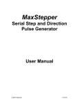
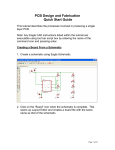
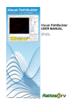
1
KCAM 4
CNC CONTROL SOFTWARE
USER MANUAL
© 2007 KellyWare
2/6/2007
KCam User Manual
Table of Contents:
Introduction....................................................................................................................................................................... 3
Quick Start with KCam..................................................................................................................................................... 4
Pull down Menus .............................................................................................................................................................. 5
File............................................................................................................................................................................... 5
Open Gcode File..................................................................................................................................................... 5
Save Gcode File ..................................................................................................................................................... 5
Import..................................................................................................................................................................... 6
Import DXF file ................................................................................................................................................ 6
Import HPGL .................................................................................................................................................... 6
Import Excellon ................................................................................................................................................ 6
Import Gerber.................................................................................................................................................... 6
Export..................................................................................................................................................................... 7
Export DXF file ................................................................................................................................................ 7
Export HPGL file .............................................................................................................................................. 7
Recent File List ...................................................................................................................................................... 7
Print........................................................................................................................................................................ 7
Exit ......................................................................................................................................................................... 7
EDIT............................................................................................................................................................................ 7
Find.............................................................................................................................................................................. 7
Replace ........................................................................................................................................................................ 7
VIEW .......................................................................................................................................................................... 7
Plot ......................................................................................................................................................................... 7
Gcode ..................................................................................................................................................................... 8
CNC Control .......................................................................................................................................................... 8
Parallel I/O Display .............................................................................................................................................. 13
Save Form View................................................................................................................................................... 13
Load Default Form Positions................................................................................................................................ 13
MACHINE SETUPS ................................................................................................................................................. 13
Create New Machine Setup .................................................................................................................................. 13
Machine Setups: ................................................................................................................................................... 13
Setup.......................................................................................................................................................................... 13
Options ................................................................................................................................................................. 13
System Timing ..................................................................................................................................................... 17
Table Setup........................................................................................................................................................... 17
Port Setup ............................................................................................................................................................. 20
Macro Files........................................................................................................................................................... 24
Tool List ............................................................................................................................................................... 24
Event Sounds:....................................................................................................................................................... 24
FUNCTIONS............................................................................................................................................................. 25
Scale Gcode.......................................................................................................................................................... 25
Offset Gcode ........................................................................................................................................................ 25
Convert Gcode to Absolute .................................................................................................................................. 25
Convert Gcode to Incremental.............................................................................................................................. 25
WINDOW ................................................................................................................................................................. 25
Window List......................................................................................................................................................... 25
HELP......................................................................................................................................................................... 25
Help Contents....................................................................................................................................................... 25
About.................................................................................................................................................................... 25
Registration .......................................................................................................................................................... 25
Supported G Codes ......................................................................................................................................................... 26
Supported M Codes ........................................................................................................................................................ 26
User Defined M codes .................................................................................................................................................... 26
Supported DXF version R12 Formats............................................................................................................................. 27
Hardware Connections.................................................................................................................................................... 27
Glossary .......................................................................................................................................................................... 28
Registering KCam........................................................................................................................................................... 28
Shareware ....................................................................................................................................................................... 28
-2-
KCam User Manual
Introduction
Thank you for choosing KCam. KCam is designed to make your CNC experience simple and
enjoyable. A wide variety of features are available to perform functions typically only found in
more expensive CNC packages. Typical CNC applications for KCam include Routing,
Signage, 3D Milling, PCB Milling and Drilling, and Plasma Cutting. KCam is designed to read
files created by your design applications and control the CNC equipment attached to your PC
Printer port.
Features
File formats supported: GCode, DXF, HPGL, Excellon, Gerber
Parallel Port motor controller access
Serial Port motor controller access( MaxStepper hardware only)
2D and 3D graphical plots of data
Gcode data entry
Gcode data conversions
Gcode macro sub programs
Manual jogging controls
Keyboard jogging controls
Manual gcode input
Estimated CNC processing calculation
Tool position status indicators
Dual cutting depths for sign engraving
Multiple motor enabling options
PCB Isolation Plots from Gerber(RS274X)
-3-
KCam User Manual
Quick Start with KCam
There are 3 steps to setting up your CNC table for use with KCam. Step 1 includes entering
in your machine axis parameters in the Table Setup window. Step 2 includes entering your
communication port information in the Port Setup window. Step 3 is determining the timing
parameters using the System Timing window.
Step 1 Table Setup window
Select the Units of Measurement you use (Metric or Imperial).
Select the Numerical Format (ex. 000.0000).
Enter the Steps per in for each Axis (ex 4000 IPM).
Enter the Lengths for each Axis (ex. 10 Inches).
Enter the Backlash distance(ex. .0125 Inches) for each axis(optional).
Enter the Feed Rates. (Traveling, Cutting and Jogging).
Enter a Travel Depth for the Z Axis(ex. 0.50 for 2D DXF and HPGL importing).
Enter a Normal Cut Depth for the Z Axis(ex. 0.125 for 2D DXF and HPGL importing).
Enter a Deep Cut Depth for the Z Axis(ex. 0.00 for 2D DXF and HPGL importing).
Select Backlash to True if the Backlash distances are known(optional).
Select Ramping to True if you wish Ramp Up/Down function to occur.
Enter a Ramp Start IPM (5 recommended).
Select a Ramp Rate (50 recommended).
Enter the Maximum Feed Rates for each axis.
Select the OK button.
Step 2 Port Setup window
Select the Port I/O Controls Tab.
Select Port Type (LPT or Serial Port) depending on your controller type.
Select Parallel Port I/O Dll (InpOut32 or DlPort) depending on your Operating System.
Select the Apply button.
Select the LPT Setup Tab.
Select the Pin Setup option.
Select the Pin Address(typically &H378 for LPT 1).
Enter the Output Pins associated with your motor controller step functions.
Invert each Pin as necessary to acquire the desired normal state when not moving an
axis.
Enter the Input Pins associated with your limit switches.
Invert each Pin as necessary to acquire the desired normal state when Limit/E-Stop
switches are not engaged.
Select the OK button.
Step 3 System Timing window
Select the Start Button.
Wait until the timing is complete and select OK.
Open the CNC Controls window and select the Manual tab. You can test the motors by using
the Jog Arrow buttons.
-4-
KCam User Manual
Pull down Menus
File
Open Gcode file
Save Gcode file
Import
DXF
HPGL
Excellon
Gerber
Export
DXF
HPGL
Recent File List
Print
Exit
Edit
Find
Replace
View
Plot(F4)
Gcode(F5)
CNC Controls(F6)
Parallel I/O Display
Save Form View
Load Default Form Positions
Machine Setups
Create New Machine Setup
Load Machine Setup
Setup
Options
System Timing
Table
Port
Macro Files
Tool List
Event Sounds
Functions
Scale Gcode
Offset Gcode
Convert to Absolute
Convert to Incremental
Window
Window List
Help
Help Contents
About
File
Open Gcode File
Opens an ASCII file which contain G and M codes. A browsing window will appear to enter
the file name and location.
Save Gcode File
Saves the current GCode data in the editor window to an ascii file. A browsing window will
appear to enter the file name and location.
-5-
KCam User Manual
Import
Import DXF file
Imports a DXF ascii file using the R12 format from AutoCad. A browsing window will appear
to enter the file name and location. See Supported DXF Formats for further DXF import
information
Import HPGL
Imports a HPGL ASCII file. A HPGL ascii file contains 2D plotting data. A browsing window
will appear to enter the file name and location.
Import Excellon
Imports an Excellon ascii drill file. Excellon ascii drill files contain data for drilling holes in
printed circuit boards. Excellon ascii files contain drill hole location and bit sizes. A browsing
window will appear to enter the file name and location. Some programs do not add the Drill
Size header. If your files are missing the header, check for options to add it in your CAD
software. Below is a sample file with the header and drill position coordinates:
M48
INCH,LZ
T01F00S00C0.125 [drill size header for tool 1, bit size=.125]
T02F00S00C0.028
[drill size header for tool 2, bit size=.028]
T03F00S00C0.035
[drill size header for tool 3, bit size=.035]
T04F00S00C0.042
[drill size header for tool 4, bit size=.042]
%
G90
T01
[select drill size 1(.125)]
X+03851Y+04226 [move to coordinate X,Y and drill]
X+03851Y+01163 [move to coordinate X,Y and drill]
T02
[select drill size 2(.028)]
X+02456Y+03415 [move to coordinate X,Y and drill]
X+02556Y+03415 [move to coordinate X,Y and drill]
T03
[select drill size 3(.035)]
X+03469Y+02238 [move to coordinate X,Y and drill]
X+03569Y+02238 [move to coordinate X,Y and drill]
T04
[select drill size 4(.042)]
X+03171Y+01538 [move to coordinate X,Y and drill]
X+03371Y+01538 [move to coordinate X,Y and drill]
T00
M30
Import Gerber
Imports a Gerber ASCII file. An Isolation Plot will be created if the Isolation option is Checked
in Options(Gerber Tab). A Gerber ASCII file contains 2D plotting data. A browsing window
will appear to enter the file name and location. If the file contains more than one layer, a
layer selection window will appear. In that window you can select which layers you want to
import.
See Gerber Options
Note: The Gerber Import function only works with Gerber(RS274X) single layer files. A
Gerber(RS274X) file has the aperture list in the file included with the line data. If a file is
-6-
KCam User Manual
imported without a correct aperture list the resultant gcode data will not be correct.
Note: For trial purposes the Gerber entities will be limited to 100. Please send us
comments and suggestions pertaining to the isolation import process.
Known Issues with Isolation Imports:
1) Speed, the isolation import function is slow. The number of calculations are exponential
with polygon count.
2) When a corner or side of a polygon is inside two or more other polygons, extra cut lines
are produced.
3) When two intersecting lines have the same slope, extra cutting lines are produced.
Export
Export DXF file
Exports a DXF ASCII file from the data in the GCode editor. The exported DXF file format
will be AutoCAD R12. A browsing window will appear to enter the file name and location.
See Supported DXF Formats for further DXF Export information
Export HPGL file
Exports a HPGL ASCII file from the data in the GCode editor. A browsing window will appear
to enter the file name and location.
Recent File List
The Recent File List is located in the File pull down menu. Files which have been opened
before can be quickly accessed by selecting them in the Recent File List.
Print
Prints the current window.
Note: Currently only the Plot and Gcode windows are supported.
Exit
Exits KCam.
EDIT
Find
Finds a text string in the Gcode Editor window.
Replace
Replaces text strings in the Gcode Editor window.
VIEW
Plot
This function opens the Plot Window for viewing your gcode graphically. The Plot window
has additional buttons for changing the viewpoint of your graphical plot.
-7-
KCam User Manual
Gcode
This function opens the Gcode Editor window. The Gcode Editor window allows viewing and
editing of the gcode data. The text window operates similar to a normal windows text editor.
Functions like Cut, Paste, Find and Replace work in the text box.
CNC Control
This function opens the CNC Control window. The CNC control window allows manual and
automatic motion control for your axis along with specific information about motion
characteristics.
CNC CONTROLS WINDOW – MANUAL TAB
Arrow buttons
The Arrow buttons will move the Axis when
pressed. If the Single Step button is
engaged, the moves will continue for a
distance equal to the distance box.
Single Step button
When the Single Step button is engaged, the
Arrow button movements will continue for the
distance specified. The distance is specified
in the Distance Entry box.
Distance Entry combo box
The distance entered in this box is used for
Single Step moves. You can use the
predetermined numbers or type in your own.
Move to Home button
When the Move to Home button is pressed,
the CNC tool will move to the Home position
for all axis .The Home position is specified in
the Table Setup window. If the Home
position entry boxes are blank, those axis will
not move from their current position.
Move to ReTool button
When the Move to ReTool button is pressed,
the CNC tool will move to the ReTool position
for all axis. The ReTool position is specified
in the Table Setup window. If the ReTool
position entry boxes are blank, those axis will
not move from their current position.
Keyboard Jog button
The Keyboard Jog button will open the
Keyboard Jog window. When the Keyboard
Jog window is open, the arrow keys allow jog movements while those keys are depressed.
See the KeyBoard Jog window for more details.
Goto button
When the Goto button is pressed, the Gcode data in the Goto Data Entry box will be
immediatly processed.
-8-
KCam User Manual
Goto Data Entry box
The Goto Data Entry box is used for entering Gcode commands to be performed when the
Goto button is pressed. Only single line commands are allowed to be entered.
Feed box
The Feed Rate box displays the feed rate the motors are moving at. This value is calculated
from the timing signals sent out the ports.
Override box
The Throttle Override box adjusts the feed rate the motors are moving at in real time. This
can be used to slow down cutting feed rates during an operation.
Auto Tune button
The Auto tune button performs "on the fly" System Time Constant adjustments for parallel
port users. It should only be used when the tool is not cutting material. Make sure it is not
engaged while cutting materials or motor positions may be compromised. After use the axis
positions should be Zeroed for accuracy.
Motor Enable button
The Motor Enable button is a software E-Stop. It will halt all movements immediatly.
E-Stop Switch
The E-Stop Switch indicator displays the current status of the external E-Stop input.
-9-
KCam User Manual
CNC CONTROLS WINDOW – AUTO TAB
Starting Step
This is the first Gcode line that will be
executed when the automatic process is started.
Ending Step
This is the last Gcode line that will be
executed when the automatic process is running.
CNC Start Process
This buttons starts the automatic CNC
process.
CNC Pause Process
This buttons pauses the automatic CNC
process.
CNC Step Process
This buttons steps the automatic CNC
process after a pause.
CNC Stop Process
This buttons stops and resets the automatic
CNC process.
CNC Process Status Box
This indicates the current CNC process.
AUTO RETOOL
This buttons pauses the automatic CNC
process and moves the axis to the ReTool
position.
Step Status
This displays the current step number to be
executed.
Step Gcode
This displays the current step Gcode to be executed.
Spindle Status
This displays the current Spindle state.
Enable TMR
This displays the motor enable timer values.
Feed Rate box
The Feed Rate box displays the feed rate the motors are moving at. This value is calculated
from the timing signals sent out the ports.
Auto Tune button
The Auto tune button performs "on the fly" System Time Constant adjustments. It should only
be used when the tool is not cutting material. Make sure it is not engaged while cutting
materials or motor positions may be compromised. After use the axis positions should be
Zeroed for accuracy.
- 10 -
KCam User Manual
Motor Enable button
The Motor Enable button is a software E-Stop. It will halt all movements immediately.
E-Stop Switch
The E-Stop Switch indicator displays the current status of the external E-Stop input.
CNC CONTROLS WINDOW – TIMING TAB
Get Time Constant button
This function determines the necessary time
constant for the current feed rate.
Time Constant box
This displays the current Time Constant.
Clicking on this box allows manual changing
of the Time Constant.
Time Constant +/- buttons
Clicking on these buttons increments or
decrements the Time Constant.
Feed Rate box
The Feed Rate box displays the feed rate the
motors are moving at. This value is
calculated from the timing signals sent out
the ports.
Auto Tune button
The Auto tune button performs "on the fly"
System Time Constant adjustments. It
should only be used when the tool is not
cutting material. Make sure it is not engaged
while cutting materials or motor positions
may be compromised. After use the axis
positions should be Zeroed for accuracy.
Motor Enable button
The Motor Enable button is a software EStop. It will halt all movements immediatly.
E-Stop Switch
The E-Stop Switch indicator displays the
current status of the external E-Stop input.
- 11 -
KCam User Manual
CNC CONTROLS WINDOW – PROCESS
STATS TAB
Timer
This displays the current process timer value.
The process time value is reset when the
CNC Process is started.
Estimated Material Process Time
This displays the estimated process
completion time for the current Gcode. The
estimated time is calculated during a plot
redraw.
Feed Rate box
The Feed Rate box displays the feed rate the
motors are moving at. This value is
calculated from the timing signals sent out
the ports.
Auto Tune button
The Auto tune button performs "on the fly"
System Time Constant adjustments. It
should only be used when the tool is not
cutting material. Make sure it is not engaged
while cutting materials or motor positions
may be compromised. After use the axis
positions should be Zeroed for accuracy.
Motor Enable button
The Motor Enable button is a software EStop. It will halt all movements immediatly.
E-Stop Switch
The E-Stop Switch indicator displays the
current status of the external E-Stop input.
- 12 -
KCam User Manual
Keyboard Jog Window
While this window is open, arrow key presses will move the axis.
The Axis will only move while the keys are depressed. When the
keys are released the axis will stop immediately.
Parallel I/O Display
This function opens the Parallel I/O Display window. The
Parallel I/O Display shows the current logic states of the
parallel port pins. This function may be helpful when
diagnosing I/O problems.
Save Form View
This function saves the current Plot, Gcode and CNC Controls window size and positions.
When KCam is started again, the forms will be loaded at the save size and position.
Load Default Form Positions
This function loads the default form size and positions. This may be useful if a form is
positioned out of reach after a screen resolution change.
MACHINE SETUPS
Create New Machine Setup
This function loads a saved machine setup.
Machine Setups:
Machine setups are the parameter files for different machines. An unlimited number of
Machine setups can be stored and reloaded. All parameter information like Table Setup, Port
Setup, Options, and Tool Lists are stored in the machine setup file. An example use would
be to store parameters for two different cnc machines. Another use would be to store
different parameters for different uses on the same machine, like drilling and routing PCB's.
Setup
Options
Options General tab
Arc Resolution
The number of individual lines in a 360 degree arc. A higher
number yields an arc or circle with a smoother edge but slower
plot updates.
- 13 -
KCam User Manual
Force Plot Bit Radius
When checked the radius of plot lines will be forced to Bit radius (below) regardless of the
Tool size currently selected in the GCode. If unchecked the GCode and the Tool Size setup
will determine the plot radius of cutting lines in the Plot window..
Bit Radius
The width of the default tool bit. This is used in displaying line width on the Plot window. If
tool bits are specified in the Tool List window and tool commands are used in Gcode, this
default value is not used unless the Force Plot Bit Radius(above) is selected.
Plot Fast Draw
When checked, the Plot window data is drawn quickly. If Unchecked, the tool path can be
viewed more easily as the data is slowly redrawn.
Plot after Load/Import
When checked, the Plot window data is drawn following a Load, Import, or process function.
If Unchecked, the tool path will not be plotted automatically. This setting is useful for very
large programs where plotting time can be an issue.
Execute Dwells
When checked, the Plot window redraw functions will execute dwell commands. This
function should be left unchecked except when verifying dwell times for plasma cutting or
similar applications.
Plot Table Grid
When checked, the Plot window will show the CNC table in the form of a grid. When
unchecked the Plot window will only show the GCode plot lines. The Z axis display is also
effected by this setting.
Display Line Nodes
When checked, the Plot window data will show small circles at the end of each line. This is
designed for diagnostic purposes where adjoining lines must be detected. Normally this
should remain unchecked for plot speed purposes.
Def. X Offset
The default axis offset value used when the Offset Gcode function is performed.
Def. Y Offset
The default axis offset value used when the Offset Gcode function is performed.
Def. Z Offset
The default axis offset value used when the Offset Gcode function is performed.
Options Gcode tab
Add Dwell Commands
When Checked, import functions will insert dwell time and dwell
execution commands into the Gcode.
Add Spindle On/Offs
When Checked, import functions will insert M03 and M05
commands into the Gcode to control the spindle before and after
each Z axis plunge. This feature is designed for torch users to engage the torch prior to each
cut.
Default Dwell Time
This is the dwell time parameter that importing functions use for inserting dwell instructions
into the Gcode.
- 14 -
KCam User Manual
I and J are Incremental
When Checked the Gcode Arc commands use the I and J values in an incremental format.
This effects importing DXF, HPGL files and plotting Gcode data.
Colors
The Plot window colors can be modified by setting the color values for the associated color
boxes.
Options DXF tab
Sort Entities
When Checked, Entities are sorted by position prior to
generating the Gcode data during a DXF file import process.
Using this feature with large files will severely increase the
import time, but the Gcode will be more efficient.
Sort Layers
When Checked, layers are sorted alphabetically prior to generating the Gcode data during a
DXF file import process.
Ignore Z Depth
When Checked, Z axis coordinates in the DXF file are ignored and parameters from the
Table Setup are used for setting the depths. If unchecked, Z coordinates from the DXF file
are used if they are present.
DXF Cut 2 Layer
This text parameter determines which layer is used for the Deep Cut Depth when importing
DXF files. This is useful for cutting through the material on holes and borders in engraving
plates.
Line Tolerance
This parameter joins non connected lines together during a DXF Import. Lines with adjacent
end points that are closer than this parameter will be joined together. This function is useful
when CAD programs used to create the DXF files do not snap the end points together, but
instead leave very small gaps between lines. If this parameter if too small (.000001) it will not
join lines. If it is too large(.1), it may join unwanted lines together. It is recommended that its
value be small until it is needed.
Options Excellon tab
Sort by Size
When Checked, drill holes are sorted by size prior to generating
the Gcode data during a Excellon file import process.
Sort by Location
When Checked, drill holes are sorted by position prior to
generating the Gcode data during a DXF file import process.
When both size and location sorts are selected, holes will be sorted by location first and then
size. Example: all .028 holes will be drilled first(sorted by location) and then the .040 holes
will be drilled(sorted by location)...
Default Bit Size
This is the tool size that will be used if no tool sizes are available in the files tool header.
- 15 -
KCam User Manual
Leading Zeros
This parameter sets the numeric format for reading the coordinates from the excellon file.
When selected it will expect a leading zero format from the data coordinates.
Trailing Zeros
This parameter sets the numeric format for reading the coordinates from the excellon file.
When selected it will expect a trailing zero format from the data coordinates.
Integers and Decimals
These two parameters set numerical format of the coordinate data from the Excellon data file.
Typically Excellon files use 2:3 format which represents 2 digits for the integer portion and 3
digits for the decimal portion of the data. Leading and Trailing Zero formats work with this to
assign the proper numerical format for the imported data. Check the output options in your
CAD application to determine the proper settings for these parameters.
Options HPGL tab
Def. Pen Size
This is the default pen size when importing a HPGL file.
Sort Entities
When Checked, Entities are sorted by position prior to
generating the Gcode data during a HPGL file import process.
Using this feature with large files will severely increase the
import time, but the Gcode will be more efficient.
Options Gerber tab
Cleanup Gerber Data
When selected the Gerber Import will remove redundant and
overlapping objects.
Trace Isolation
When selected the Gerber Import will convert Gerber(RS274X)
photo plot lines to grouped polygons for PCB trace milling.
Cleanup Lines
This option will remove some unwanted lines the polygon isolating program leaves behind. It
can also reduce poly lines to single lines when the slopes match.
Sort Entities
When selected the Gerber Import function will sort the isolated polygons by location. This
option reduces cutting time.
Tool Radius
This option adds a tool radius to the Gerber polygon diameters. It can enlarge the plot
entities to increase pad and line thickness. changing this value can also reduce the isolation
imperfections on some Gerber files.
Minimum Line Size
Line sizes the same or smaller than this parameter are processed using the following
functions.
Discard Minimum Lines option
This option forces the isolation process to ignore objects this diameter and smaller. It
- 16 -
KCam User Manual
decreases import time by ignoring small entities such as text.
Draw as Lines option
This option forces the isolation process convert objects this diameter and smaller to single
line entities not outlined entities.
Note: Gerber(RS274X) format is the only gerber format supported. If your files do not
import properly, check to ensure they have a valid aperture header.
System Timing
This function opens the System Timing window. The System Timing
window determines calibration data specific to the PC in use. This
calibration data adjusts the axis velocities for accurate motion.
Table Setup
This function opens the Table setup window. The Table setup window allows editing of
CNC table parameters.
Table Setup Parameters:
Units Of Measurement
The numerical measurement type.
Millimeters or Inches
Numeral Format
Pre and Post zeros used in
formatting numbers in the Gcode
Editor.
Steps/Inch or Steps/mm
The number of steps required to
move an axis one inch or one
millimeter.
Axis Length
The maximum mechanical travel of an axis.
Axis Invert
The axis direction is normal when set to False.
The axis direction is reversed when set to True.
Backlash
The distance necessary to overcome play or errors in the axis mechanics due to wear or
looseness of components. Backlash errors are most visible when an axis changes direction.
Travel Depth
The default Z axis depth for rapid movements. Used in engraving for rapid movements
without cutting material.
Cut Depth
The default Z axis depth for cutting. Used in engraving for cutting letters and designs.
Aux Depth
The default Z axis depth for cutting through the material. Used in engraving for cutting holes
- 17 -
KCam User Manual
and borders.
Backlash
When set to False, backlash compensation is not used.
When set to True, backlash compensation is used.
Ramping
When set to false, the axis start and run at the specified feed rate.
When set to true, the axis start slowly, increase speed, and finish slowly.
This functions allows greater axis speeds, due to inertial limits of steppers and axis
mechanics.
Ramp Start
This sets the starting and ending speed of the axis if ramping is enabled. The number
represents an absolute feed rate.
Ramp Rate
This sets the ramp up and down time or velocity envelope. This number represents the
amount of IPM change in an Inch or mm of movement.
Feed Rates
These are the default feed rates for moving the axis. Travel Feed Rate is for high speed
moves such as G00 commands. The Cutting Feed Rate is for G01 commands. The Jogging
Feed Rate is for Jog buttons or keyboard movements.
Note: The Cutting Feed Rate is overridden when Gcode program feed rate commands
specify the feed rate.
Maximum Feed Rates
These are the maximum Feed Rates allowed per axis. These parameters are useful when
certain axis are unable to operate at the same rate as the rest. For example, the Z axis may
not operate as fast as the X and Y. In this case the Z axis Maximum Feed Rate would be set
lower the the X and Y.
Invert Z Coordinates
This reverses the Z axis coordinate system.
Hide Axis Cursor
When Checked the milling cursor will not be displayed on the Plot window. This function
improves the step pulse train uniformity.
Disable Position Update
When Checked the axis positions will not update until the movement is complete. This
function improves the step pulse train uniformity.
Enable Z Axis Jog Step
When Checked the Z axis can be jogged specific distances. When unchecked the Z axis can
only be jogged while the jog keys are pressed. This is a safety feature to avoid jogging the Z
axis into the table when using Jog Distances.
Limit Switches Disabled
When Checked the Limit Switches are not polled during operation and will not stop the Axis.
It will speed up the maximum step rate. This function is useful when you do not have limit
switches available or want faster step rates. When it is set or reset(changed) the System
Timing function should be performed.
Application Priority
- 18 -
KCam User Manual
These options determine how KCam operates within the Microsoft Windows environment.
When normal priority is selected, KCam operates like any standard window. When high
priority is selected, KCam will operate with more priority than other programs and step pulse
streaming may improve. When realtime priority is selected, KCam will have much more
priority than other applications or processes within Windows. Be aware that realtime mode
can make KCam seem unresponsive
.
Table Setup Parameters:
Home Position
The position the axis will return to when the Home Button has executed. If the Home position
is blank, the axis will remain in its current position for the Home function.
The Homing(without validation) axis sequence is as follows:
Z axis moves to the Travel position
X and Y move to their Home position
Z moves to its Home position
Home Validation:
Validate Position checkbox enables the home validation process.
Direction Parameters are the positions the axis will travel towards.
Target Parameters are the positions the axis will be set to.
Fast IPM is the rate the axis will find the limit switches at.
Slow IPM is the feed rate the axis will recheck the limit positions.
Home Validation is the process of reseting the position counters by finding the limit switches.
When selected the axis will validate their positions using the limit switches when the Home
button is pressed. Typically the Direction positions should be -1,-1,4 for the X,Y,Z axis and
the Target positions are 0,0,3 for the X,Y,Z axis.
Below is an explanation of what happens during validation process using the above settings:
1) The "Validate Position" option must be checked.
2) The user presses the "Home" button in the CNC Control window.
3) The Z axis moves towards position 4(Direction) at the Fast IPM rate until a limit switch is
found.
4) It taps the limit switch 3 times using the Slow IPM rate and sets the current Z position to
0(Target).
5) The X axis moves towards position -1(Direction) at the Fast IPM rate until a limit switch is
found.
6) It taps the limit switch 3 times using the Slow IPM rate and sets the current X position to
0(Target).
7) The Y axis moves towards position -1(Direction) at the Fast IPM rate until a limit switch is
- 19 -
KCam User Manual
found.
8) It taps the limit switch 3 times using the Slow IPM rate and sets the current Y position to
0(Target).
9) The Z axis moves to the Home Position
10) The X and Y axis move towards the Home Position
ReTool Position
The position the axis will return to when a tool change command is executed. If the ReTool
position is blank, the axis will remain in its current position for the tool change.
The ReTool axis sequence is as follows:
Z axis moves to the Travel position
X and Y move to their ReTool position
Z moves to its ReTool position
Table Setup Parameters:
Jog Key Assignment:
The Manual Jog Keys can be reassigned for custom keyboard. To assign a new key, select
an axis direction button and press the key to activate that axis direction. A Key Test window
opens during the key assignment to grab the desired key press and determine its ascii value.
Restore Defaults
This function will return the Jog Keys to the Numerical Keypad keys for jogging.
Default Keys:
Numerical Keypad Arrows move the X and Y axis. Keys 7,9,1,3 move the X and Y axis
together.
The Numerical Keypad - and + keys move the Z axis up and down respectively.
The < and > keys change the feed rate.
Check Key Value
This function will open a test window that shows the ascii value of keys pressed.
Port Setup
This function opens the port setup window. The Port setup window allows editing of the
communication port parameters.
Port I/O Controls:
- 20 -
KCam User Manual
Port Type
The Port Type selects the communication port for accessing the stepper motor controllers.
Parallel Port I/O Dll used
The Parallel Port I/O Dll used selects to DLL windows uses to access the parallel port. Either
can be used under Windows 95 and 98. If Windows NT operating system is used then
DlPort.dll must be used.
MaxStepper Setup:
Port Status:
MaxStepper Com Port: Determines which serial port KCam uses to communicate with
MaxStepper. The serial port choices are 1, 2, 3 or 4.
Communication: Displays the status of the serial connection to MaxStepper.
Comms: Total number of communication attempts by KCam to MaxStepper.
Errors: Number of erroneous communication attempts by KCam to MaxStepper.
CS Er: Number of CheckSum type communication errors.
Len Er: Number of bad length type communication errors.
Buffer: Number of motion command strings waiting in the command buffer.
Rev: Firmware revision in MaxStepper
- 21 -
KCam User Manual
Date: Date of firmware in Maxstepper
Hz: Current pulse rate in Hertz that Maxstepper is applying to the stepper motors.
CByte1: Displays the control byte for Axis X,Y,Z and A
CByte2: Displays the control byte for future axis.
Status Message: Information on Maxstepper Communication status
LPT Setup:
Pin Setup Port:
Bit Setup
When this option is selected, the bit setup parameters are enabled.
Pin Setup
When this option is selected, the pin setup parameters are enabled.
Pin Address
The address of the LPT port used to communicate to the stepper motor controllers for Pin
Setup. The address is used to convert the Pin Setup to the more advanced Bit Setup.
Output Setup:
Pin
The pin number on the 25 pin D-Sub LPT connector used to perform the specified motor
controller function.
Port
The port address of the bit used to access the specified controller function.
Bit
The Bit used to access the specified controller function.
Inverted
Specifies the normal state of the output pins.
Input Setup:
Pin
The pin number on the 25 pin D-Sub LPT connector used to perform the specified Limit or E-
- 22 -
KCam User Manual
Stop switch function.
Port
The port address of the bit used to access the specified controller function.
Bit
The Bit used to access the specified controller function.
Inverted
This function inverts normal state of the bit for the controller.
Auxiliary MCode Output Setup:
Pin
The pin number on the 25 pin D-Sub LPT connector used to perform the specified motor
controller function.
Port
The port address of the bit used to access a user defined controller function.
Bit
The Bit used to access the a user defined controller function.
Motor Enable:
This function defines how the motor controller axis enable bits are controlled.
On with Step turns the enable bits on only while a stepping process is in progress.
Always On turns on the enable bits with the first stepping process and leaves them on until
KCam is exited.
Timed (off delay) turns the enable bits on during stepping process and turns the bits off a
specified time ( in seconds) after the last stepping process has completed.
LPT Info:
This window gives general information on the parallel port. This information can be used for
determining how to connect a stepper motor controller to a PC.
- 23 -
KCam User Manual
Macro Files
This function opens the Macro Files window. The Macro Files window allows editing of the
macro file names and macro file numbers. Macro Files are used for sub program calls
within your main gcode program to perform repetitive functions with code efficiency. Macro
files are called using M98 in the gcode file. The format is M98 x, where x is the macro file
number stored in the Macro File list.
Example:
N001 [MACRO EXAMPLE]
N002 [DRAW THE SERIAL NUMBER 99633524]
N003 [USING MACROS]
N004 G90
N005 G00 Z1.000
N006 X0 Y0
N007 M98 9 [CALL MACRO FILE 9]
N008 X.11
N009 M98 9 [CALL MACRO FILE 9]
N010 X.11
N011 M98 6 [CALL MACRO FILE 6]
N012 X.11
N013 M98 3 [CALL MACRO FILE 3]
N014 X.11
N015 M98 8 [CALL MACRO FILE 8]
N016 X.11
N017 M98 5 [CALL MACRO FILE 5
N018 X.11
N019 M98 2 [CALL MACRO FILE 2]
N020 X.11
N021 M98 4 [CALL MACRO FILE 4]
N022 X.11
N023 G00 X0 Y0
Tool List
The Tool List allows editing of tool bit diameters. Tool bits are accessed through the Gcode
by using the T command. A maximum of 200 tool sizes can be saved in each file. When
Importing an Excellon file, tool diameters are automatically generated from the aperture list.
Tool Offsets are also edited here. The Tool Offset function is not yet implemented.
Clear All
The Clear All button clears all the tool diameters in the list. When the tool list is cleared, the
Plot window uses the Bit Radius in Options (General Tab) for displaying plot lines
Using the Load or Save buttons, different tool files can be stored and reloaded for various
machine setups.
Event Sounds:
The list shows the available events that
sounds can be assigned to. To change a
sound for an event, double click on the event
to open a browse window for file selection.
You can right click on a selected event to hear
the assigned sound.
- 24 -
KCam User Manual
FUNCTIONS
Scale Gcode
This function scales the gcode in the editor window. A pop
up entry box will appear to enter X and Y scale data. If the
X or Y Scale data is blank or 0, no scaling will be performed.
Offset Gcode
This function offsets the gcode in the editor window. A pop
up entry box will appear to enter offset data for each axis. If
the offset data is blank or 0, no offset will be performed for
that axis.
Convert Gcode to Absolute
This function converts the gcode in the editor window to absolute format.
Convert Gcode to Incremental
This function converts the gcode in the editor window to incremental format.
WINDOW
Window List
Displays the open child windows. If a window is underneath another,
it can be brought forward by selecting it from the window list.
HELP
Help Contents
Opens the help contents file.
About
This function opens the About window. The About window
shows the software version, Registration button and
System Information button.
Registration
Registration information can be entered to allow full use of the software and remove time
limits. In order to register your version of KCam you must obtain a Key Code from Kellyware.
- 25 -
KCam User Manual
Supported G Codes
G Code
Description
G00
Rapid Traverse
G01
Normal Traverse
G02
CW Arc
G03
CCW Arc
G04
Execute Dwell Time
G17
XY Plane Selection
G18
XZ Plane Selection
G19
YZ Plane Selection
G40
Cancel Cutter Diameter Compensation
G41
Start Cutter Diameter Compensation Left
G42
Start Cutter Diameter Compensation Right
G45
Normal Traverse
G73
Drill Cycle
G80
End Drill Cycle
G81
Drill Cycle
G82
Drill Cycle with Dwell
G83
Drill Cycle
G90
Sets Absolute Mode
G91
Sets Incremental Mode
Pxx
Sets Dwell Time to xx
Fxx
Sets Feed Rate to xx
Supported M Codes
M Code
M00
M01
M02
M03
M04
M05
M06
M07
M08
M09
M13
M30
M60
M98
Description
Program Stop
Optional Program Stop
Program End
Engage Spindle Relay
Engage Spindle Relay
Disengage Spindle Relay
Tool Change
Mist Coolant On
Flood Coolant On
Mist and Flood Coolant On
Engage Spindle and Coolant
Program End and Reset
Program Stop
Call Macro subroutine
User Defined M codes
Mxx
Mxx
Mxx
Mxx
Mxx
Mxx
Engage user defined output
Disengage user defined output
Engage user defined output
Disengage user defined output
Engage user defined output
Disengage user defined output
xx is the number given by the user
- 26 -
KCam User Manual
Supported DXF version R12 Formats
Entity
Line
Poly line
Vertex
Point
Arc
Circle
Description
Single Line X1,Y1,Z1 TO X2,Y2,Z2
Multiple Line X1,Y1,Z1 to following vertexes
Multiple Line to X2,Y2,Z2
Single Point X1,Y1,Z1
CCW Arc Entity
Full Circle Entity
Note:
Text items do not import. TurboCAD v5.0 and v6.0 have a text property call FLEXIBLE which
will convert the text entity into polylines.
Hardware Connections
KCam has two motor control port options, Parallel and Serial. In Parallel Port mode KCam
requires step and direction motor drivers. In order to get movements from the PC to the
CNC table KCam pulses or changes the state of pins on the parallel port on your PC. In
Serial Port mode the MaxStepper needs to be connected to the serial port and step and
direction motor drivers to MaxStepper.
Parallel Mode Information:
Each motor controller needs to have a Step input connected to a Pin on the parallel port.
This input on the controller advances(rotates) the stepper motor when pulsed. A Direction
input is also required to tell the controller which direction to move when the step input is
pulsed. An Enable input is used to tell the controller to apply current to the motor. The
Enable function is optional and some controller don't use it. If you have a controller that has
an Enable input, you should use it. It will shutdown the motors when they are not in use and
protect them from overheating.
Parallel port mode can be used with port cards other than just a parallel port. The Parallel
Port Setup allows Bit Mode for assigning access for the step and direction addresses in a
unique card. Each brand of I/O Card has different port addressing schemes and correct
settings in KCam must be determined by the end user using documentation for the card.
Typical Parallel Port Connections
- 27 -
KCam User Manual
Glossary
Axis
Backlash
CNC
Ramp Rate
IPM
An Axis is a motorized portion of a machine.
Backlash is the play in the threads between the drive nut and threaded rod on an axis. This play
causes a loss of distance in a movement when the direction changes.
CNC is the abbreviation of Computer Numerical Control. Or simplified its the computer control of
machines.
The Ramp Rate is the acceleration and deceleration rate of the stepping velocity. Its value is
given in change of IPM per Inch.
IPM is the measurement of velocity or speed for an axis. It is the abbreviation of Inches Per
Minute which is a rate of movement.
Registering KCam
To register your copy of KCam please visit our web site www.kellyware.com for details.
To obtain your registration code, open http://www.kellyware.com/kcam/kcam_registration.htm in
an internet browser. Click on the "PayPal Buy Now" button. You can enter your credit card
information and a VALID email address. Please make sure your Email Address is correct. Once
Kellyware has received notice of your payment a personal registration code will be generated and
sent to the email address given to PayPal. You need to enter the user name and registration
code into KCam's Registration form. You can find this form by clicking on
"Help/About/Registration". Your registration code will be sent to you in about 1 to 3 business
days. Registration responses times may vary.
Note:
If PayPal does not support your country, you can try a nearby country or mail payment to
Kellyware. Details on sending payment are available at
http://www.kellyware.com/kcam/kcam_registration.htm.
Shareware
KCam is shareware until a valid registration code is entered. Until KCam is registered, a user has
a 60 day or 60 execution trial period until the software becomes limited. During the trial period
KCam has no limitations. After the trial period has finished, some functions are disabled or
limited.
After Trial Limitations include:
Gcode saving is disabled
Gcode lines are limited to 500
Gerber Isolation lines are limited to 100
- 28 -