1
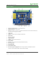
share awesome hardware High-Precision AD-DA User Manual High-Precision AD/DA Board User Manual Overview There's no AD/DA function on the Raspberry Pi GPIO interface, this may troubled you in the Pi development. However, it won't be a problem anymore. The High-Precision AD/DA Board allows you to add high-precision AD/DA functions to the Raspberry Pi. Supported Pi Raspberry Pi 1 Model A+ Raspberry Pi 1 Model B+ Raspberry Pi 2 Model B Features Onboard ADS1256, 8ch 24bit high-precision ADC (4ch differential input), 30ksps sampling rate Onboard DAC8552, 2ch 16bit high-precision DAC Onboard input interface via pinheaders, for connecting analog signal the pinout is compatible with Waveshare sensor interface standard, easy to connect various analog sensor modules Onboard input/output interface via screw terminals, for connecting analog/digital signal Features AD/DA detect circuit, easy for signal demonstration 1 Revision: 1.1. Date: July 17 2015. Author: Zhou Jie. Editor: Felix High-Precision AD-DA User Manual share awesome hardware What's on Bo ard 1. Raspberry Pi GPIO interface: for connecting with the Pi 2. AD/DA input/output: screw terminals 3. AD input: pinheaders, the pinout is compatible with Waveshare sensor interface standard, easy to connect various analog sensor modules 4. 7.68M crystal 5. LM285-2.5: provides reference voltage for the ADC chip 6. Photo resistor 7. LED output indicator 8. 10K potentiometer 9. DAC8552: 16bit high-precision DAC, 2ch 10. Power indicator 11. ADS1256: 24bit high-precision ADC, 8ch (4ch differential input) 12. ADC testing jumper 13. DAC testing jumper 14. Power selection jumper 15. ADC reference ground configuration: when AD single inputted, the AINCOM is reference terminal, can be connected to GND or external reference voltage 2 Revision: 1.1. Date: July 17 2015. Author: Zhou Jie. Editor: Felix High-Precision AD-DA User Manual share awesome hardware Symbol descriptions 1) AD/DA input/output (Tab 2) AD0-AD7: Analog input AGND: Analog ground GND: Digital ground VCC: Power supply (3.3V and 5V optional, can be switched by setting the Power selection jumper) DA0-DA1: Analog output 2) Analog input (Tab 3) AD0-AD7: ADS1256 analog input D0-D3: GPIO of ADS1256 (See ADS1256 datasheet) P22-P25: GPIO of Raspberry Pi AGND: Analog ground 3) LDR: Light-dependent resistor, i.e. Photo resistor (Tab 6) By connecting the jumper between AD1 and LDR, the MCU can read the voltage output of LDR from the pin AD1. 4) LEDA/LEDB: LED output indicator (Tab 7) By connecting the jumper between LEDA/LEDB and DAC0/DAC1, the voltage output of DAC0/DAC1 can be estimated roughly by the brightness of LEDA/LEDB. 5) ADJ: The adjustable resistor of the 10K potentiometer (Tab 8) By connecting the jumper between AD0 and ADJ, the MCU can read the voltage output of the potentiometer from the pin AD0 6) PWR LED: Power indicator (Tab 10) 7) Power selection jumper (Tab 14) VCC: Power supply selection VREF: Reference input voltage 3V3: 3.3V output 5V: 5V output 8) JMP_AGND: Analog ground jumper(Tab 15) For single-ended measurements, use AINCOM (Analog input common) as common input, which can be connected to AGND or external reference voltage. For differential measurements, do not use AINCOM. 3 Revision: 1.1. Date: July 17 2015. Author: Zhou Jie. Editor: Felix High-Precision AD-DA User Manual 1. share awesome hardware Basic operation of Raspberry Pi Before using the module with Raspberry Pi, such basic operations are required: Using Raspberry Pi image Using Linux Terminal If you have already known them, please skip this section directly. 1.1. How to use Raspberry Pi image 1) Download the Raspbian image from http://www.raspberrypi.org/downloads/ 2) Unzip the downloaded file and get an .img file. 3) Run the software Win32DiskImager.exe then select the Image File (the .img file) and Device(The TF Card Reader), click the button write to program the system image file. Note: The capability of TF card in used here should be more than 4GB. In this operation, a TF card reader is also required. 4) Plug in the programmed TF card to the TF card socket on a Raspberry Pi, and then power up to start the Raspbian OS. (System Configuration may be required for the first time boot up) 1.2. How to use the term inal of Ra spberry Pi? All the supported software should run under the Linux terminal. If you have a HDMI monitor, just connect it to the Pi directly then open the terminal at the GUI. If not, you can operate the terminal of Pi using SSH. 1) Connect the Pi and a router via a network cable. 2) Run the software PuTTY on the PC connected to the router, fill the IP address and Port of the Pi. You can get the Pi’s IP from the router. And the Port is 22 by default. 3) Connection type is set to SSH. 4) Click the button Open to enter the Pi’s terminal. At the first boot up, please input: User name: pi Password: raspberry 4 Revision: 1.1. Date: July 17 2015. Author: Zhou Jie. Editor: Felix High-Precision AD-DA User Manual 2. share awesome hardware Getting started The following API source codes should be run under the bcm2835 library, which can be downloaded from http://www.airspayce.com/mikem/bcm2835/ 2.1. Analog to digital conver sion 1) Connect the High-Precision AD-DA Board to the Raspberry Pi. 2) Jumper settings: Set the Power Supply to 5V: connect the pin 5V and VCC. Set the Reference Input Voltage to 5V: connect the pin 5V and VREF. Set the Potentiometer output as an Analog Input: connect the pin ADJ and AD0. Make sure the left side Sensor Interface AD0 is disconnected. Set the LDR output as an Analog Input: connect the pin LDR and AD1. Make sure the left side Sensor Interface AD1 is disconnected. Connect AINCOM to AGND. When using AD for differential measurements, the common input AINCOM does not need to be tied to ground. 3) When using SSH for terminal control, please connect the network cable. The software PuTTY should be installed. See the section 1.2. 4) Power up. 5) Copy (using a USB drive as a carrier) the software directory, ADS1256, to the Raspbian OS. Note: the system will detect the USB drive directly under GUI, else if using SSH Connection, the USB drive cannot be operated until it is mounted to the Linux. Search the key words “Linux mount” for more details. 6) Make the files: Enter the directory ADS1256, and execute make to compile it. 7) Execute sudo ./ads1256_test Note: if it prompts command not found, please use chmod +x ads1256_test to add execute permission. 8) Block the LDR from light and then the voltage of channel AD1 will be changed. 9) Turn the potentiometer and the voltage of channel AD0 will be changed. 10) In the end, press Ctrl+C to suspend the current process. 2.2. Digital to a nalog conversion 1) Connect the High-Precision AD-DA Board to the Raspberry Pi. 5 Revision: 1.1. Date: July 17 2015. Author: Zhou Jie. Editor: Felix High-Precision AD-DA User Manual 2) share awesome hardware Jumper settings: Set the Power Supply to 5V: connect the pin 5V and VCC. Set the Reference Input Voltage to 5V: connect the pin 5V and VREF. Connect the pin DA0 to LEDA, the pin DA1 to LEDB. Then the brightness of LEDA indicator will be changed according to the voltage output of DA0 and the brightness of LEDB indicator will be changed according to the voltage output of DA1. 3) When using SSH for terminal control, please connect the network cable. The software PuTTY should be installed. See the section 1.2. 4) Power up. 5) Copy (using a USB drive as a carrier) the software directory, DAC8552, to the Raspbian OS. Note: the system will detect the USB drive directly under GUI, else if using SSH Connection, the USB drive cannot be operated until it is mounted to the Linux. Search the key words “Linux mount” for more details. 6) Make the files: Enter the directory DAC8552, and execute make to compile it. 7) Execute sudo ./dac8552_test Note: if it prompts command not found, please use chmod +x dac8552_test to add execute permission. 8) Expected result: the brightness of LEDA and LEDB changes gradually. 6 Revision: 1.1. Date: July 17 2015. Author: Zhou Jie. Editor: Felix share awesome hardware High-Precision AD-DA User Manual 3. Interface Definition Pin Symbol Description 1, 17 3.3V Power supply (3.3V) 2, 4 5V Power supply (5V) 3, 5, 7, 8, 10, 18, 22, NC NC GND Ground 11 DRDY ADS1256 data ready output, low active 12 RESET ADS1256 reset input 13 PDWN ADS1256 sync/power off input, low active 15 CS0 ADS1256 chip select, low active 16 CS1 DAC8552 chip select, low active 19 DIN SPI data input 21 DOUT SPI data output 23 SCK SPI clock 31, 33, 35, 37 GPIO extend to sensor interface 24, 26, 27, 28, 29, 32, 36, 38, 40 6, 9, 14, 20, 25, 30, 34, 39 7 Revision: 1.1. Date: July 17 2015. Author: Zhou Jie. Editor: Felix High-Precision AD-DA User Manual share awesome hardware 4. Revision history Revision Changes Date 1.0 Initial release June 26 2015 1.1 Released English version manual July 17 2015 Minor edits 8 Revision: 1.1. Date: July 17 2015. Author: Zhou Jie. Editor: Felix