1
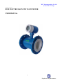
RLT Instrumentation Pvt Ltd
(Unit of RLT Group)
Version 1.01.2014
RLM ELECTROMAGNETIC FLOW METER
USER MANUAL
1
People are our prime movers
RLT Instrumentation Pvt Ltd
(Unit of RLT Group)
TABLE OF CONTENTS
PAGE NO.
1.
Working principle
4
2.
Flow Sensor Technical Specification
4
3.
Flow Meter Technical Specification
6
4.
Flange Type Specification
7
5.
Convert technical data
8
6.
Display General Operation
9
7.
Lining material selection
15
8.
Installation
17
9.
Wiring Diagram
21
10.
Trouble shooting
28
2
People are our prime movers
RLT Instrumentation Pvt Ltd
(Unit of RLT Group)
General Description
Electromagnetic flow meter suits for all kinds of liquids flow measuring such as electronic
conductivity liquid, mud and slurry etc. on the basis of its min. conductivity. The result cannot be
affected by temperature, pressure, viscosity and density.
It can also be used for measuring corrosive material as long as the right material has been chosen
for the lining material. Solid medium will not affect the result. Flow sensor and intelligent converter
compact or separately composes a complete flow meter.
Application
The main application area;
Pure Water, sewage water
Electronic manufacturer and assign
Chemistry and Industrial medicine
Food Industry
Features
No move assembly, no abrasion
Measuring range rate: 1:100
No flow enhance equipment
Suits for various of electronic conductivity liquid
No affect from temperature, viscosity, pressure and density
Anti-corrosion
Measure both to and reverse flow
Huge display, easy operate
Long-term EEPROM to save data when lose power
Support MODBUS/HART communication protocol
Wide working volts range
Self diagnose
3
People are our prime movers
RLT Instrumentation Pvt Ltd
(Unit of RLT Group)
Working principle
It’s measuring principle bases on Faraday electromagnetic induction law:
When the liquid flow through the measuring pipe which all around magnetic field, the two vertical
directions will have the induced electromotive force which is proportional with the mean velocity of
stream.
Flowmeter consists of sensor and converter. Converter transfer field current to inner loop of the sensor
to engender magnetic field. Conductivity liquid flow through the measuring pipe and get induced force
because of cutting magnetic line. By then the electrode around the pipe wall incept induced force and
transfer them to converter through signal wire. Converter filer induced force, spread, calculate and
exchange them into proportional standard Current signal and frequency signal.
Electromagnetic flow sensor
Sensor’s shell is sealed with carbon steel, only electrode and lining contact with medium.
4
People are our prime movers
m
RLT Instrumentation Pvt Ltd
(Unit of RLT Group)
Technical specification:
Reaches 8 element liquid crystal displays, current clock to indicate flow data. Two kinds of units to
choose:m3 or L.
Structure
Inserted style, compact type or separate type
liquid or solid-liquid two phase fluid, conductivity >0.5μs/cm2
Range
0.01m/s~12m/s
Accuracy
Range between 0.1m/s~10m/s can be 0.5%
DN(mm)
6 mm~3000 mm
PN6, PN10, PN16, PN25, PN40, PN63, PN100, PN160, PN250, PN420.
Output signal
4~20mA or frequency
RS485,support MODBUS protocol (not standard), Support HART (option)
Connection
DN6~DN3000 flange connection
Connection standard
Suits for all kinds of flange standard(eg:BS EN1092-1)
Standard
Accuracy apply to EN1434-1:2003 standard
CE certificate
Apply to LVD 2006/95/EC and EMC 2004/108/EC
EN 61326-1:2006 radiation standard (express apply to BS EN50081-1) EN 61326-1 : 2006 antijamming standard (express apply to BS EN50082-1), EN - 1:2001
Protection grade
IP65, IP67 & IP68
Power supply
AC 85~260V or DC 24 V
Ambient temperature
5~55°C
Ambient humidity
<85 % r.h (no condensation)
5
People are our prime movers
RLT Instrumentation Pvt Ltd
(Unit of RLT Group)
Flow spec technical spec
Application area Conductivity fluid such as cold and warm water, pure water and corrosive. Material
etc.
DN (mm)
6mm~~3000mm
PN
PN6, PN10, PN16, PN25, PN40, PN63, PN100, PN160,
PN250, PN420.
Electrode material
SS 316L
Lining material
PTFE or customize
Medium temp
0~70°C max is 180°C
Shell material
Carbon steel
Protection grade
IP65 / IP67 / IP68
Connection
all applys(eg:BS EN1092-1)
Size Specification
6
People are our prime movers
RLT Instrumentation Pvt Ltd
(Unit of RLT Group)
Flange type size spec
DN
(mm)
Lining Material
Ne
10
15
20
25
32
40
50
65
80
100
125
150
200
250
300
350
400
450
500
600
700
800
900
1000
1200
1400
1600
1800
•
•
•
•
•
•
•
•
•
•
•
•
•
•
•
•
•
•
•
•
•
•
FEP
•
•
•
•
•
•
•
•
•
•
•
•
•
•
•
•
•
PTFE
•
•
•
•
•
•
•
•
•
•
•
•
•
•
•
•
•
•
•
•
•
•
Flow Range
Normal
0.7
1.5
2.5
3.5
6
10
15
25
40
60
100
150
250
400
600
750
900
1200
1500
2500
4000
5000
6000
8000
10000
Min
0.03
0.06
0.11
0.18
0.29
0.45
0.71
0.19
1.81
2.83
4.42
6.36
11.3
17.66
25.43
34.62
45.22
57.23
70.65
101.74
138.47
180.86
228.91
282.60
406.91
553.90
723.46
915.62
Connection Size
(mm)
Size (mm)
Max
2.8
6.4
11
18
29
45
71
119
181
283
442
636
1130
1766
2543
3462
4522
5723
7065
10174
13847
18086
22891
28260
40691
55390
72346
91562
L
160
160
160
160
200
250
300
350
400
500
600
700
800
900
1000
1200
1400
1600
1800
H
254
254
254
254
270
280
294
313
326
344
372
403
460
511
565
620
675
727
782
782
1068
1157
1230
1332
1592
1870
2080
2300
B
b
152
102
φK
65
65
75
85
100
110
125
145
160
180
210
240
295
350
400
460
550
565
620
725
840
950
1050
1160
1340
1560
1760
1970
n-φd
4-φ14
4-φ14
4-φ14
4-φ14
4-φ18
4-φ18
4-φ18
8-φ18
8-φ18
8-φ18
8-φ18
8-φ22
12-φ22
12-φ22
12-φ22
16-φ22
16-φ22
20-φ26
20-φ26
20-φ30
24-φ30
24-φ34
28-φ34
28-φ36
32-φ36
36-φ36
40-φ36
44-φ39
φD
95
95
105
115
140
150
165
185
200
220
245
285
340
390
440
500
565
615
670
780
895
1010
1110
1230
1405
1630
1830
2045
Remarks:
1)
Above “•” means different DN can choose different lining material
DN50~ DN2000 Ne lining material
DN10~ DN400 FEP;
DN25~ DN1000 PTFE
2)
When chosen DN smaller than DN50, sensors standard PN is PN10
DN65~ DN200, PN16;
DN250~ DN1000, PN10;
DN1200 or above, PN6
3)
If required pressure higher than normal pressure. It needs to customize
7
People are our prime movers
RLT Instrumentation Pvt Ltd
(Unit of RLT Group)
Converter
Based on micro- technology, converter has advantages of intelligent instrument does such as
high standard, easy structure
Intelligent converter use thunder protection method design circuit which applies to various bad
environments
Long- Term store
Following data can be noted: instantaneous flow, electric information, damage information, total
flow and Max. Instantaneous flow
Total flow and reverse flow notes to current total flow. Max instantaneous can store 36 months
(monthly store), 15 years (yearly store), lose power information can have 100 items, damage
information have 20 items
Display Description
Converter has a 8 element crystal display with a diagram display pattern
This data can be displayed: instantaneous flow, total forward and reverse flow, all kinds of alarm
information and stored information.
Specifications:
Indication
128 * 64 Graphical LCD
Power supply
220 VAC ± 15 %
Power Consumption
1 Watt maximum
Flow Range
Used with line size 15mm to 3000mm
Max. Operating Temperature:
70 °C
Storage Temperature
0 – 80 °C
Humidity
0 – 80 non condensing
Accuracy
+- 1% of full scale
Relay Output Rating
NO and Common contacts with 230V 5A maximum
Saved in non-volatile EEPROM. No battery backup necessary. Data
retention 100 years maximum
From keypad provided in the instrument
Inbuilt Real Time Clock, Memory to store periodic records, Alarm
Records
Wall Mount, Panel Mount, Compact type
Program Variables:
Programming Method:
RTC & EEPROM
Housing:
Communication
Output
RS485 Isolated
4-20mA programmable according to Qmax, Pulse programmable
with number of pulses per unit where unit can be liter or m3
8
People are our prime movers
RLT Instrumentation Pvt Ltd
(Unit of RLT Group)
PRECAUTIONS
a.
Do not connect AC signals beyond the rated values to the unit. Irreparable damage will arise.
b.
Instrument power supply tolerance is +-15% from the rated supply voltage. Variations beyond
the stated limit may damage the instrument.
GENERAL OPERATION
1.Flow Setup
Instantaneous flow rate setting
1.1 PV Unit
2 PV Decimal
Optional: L/s L/m L/h m3/s m3/m m3/h
USG/s USG/m USG/h kg/s kg/m kg/h
t/s t/m t/h
Default = m3/h
Display the instantaneous flow rate display unit
Optional: 0 1 2 3
Default = 0
Display the instantaneous flow of decimal places displayed
1.3 Flow Range
Float: 99999999.00-0.00 m3/h
Default = 100.0 m3/h
Scale flow refers to the instantaneous flow rate reaches the set value,
Current output = 20mA
Changing this parameter will affect: Current output, high and low flow
alarm
1.4 Flow Cut-off
Float: 9.90 – 0.00 %
Default = 0.0 %
When the instantaneous flow rate is less than the absolute value of this
setting scale flow × percentage, making instantaneous flow = 0
1.5 Percentage of Low Float: 99.00 – 0.00 %
Default = 0.0
Flow Alarm
When the absolute value of the instantaneous flow rate is less than the
Low Alarm
percentage scale flow × this setting, the output low alarm signal
This setting value must be <high flow alarm setting percentage!
1.6 Percentage of High Float: 99.00 – 1.00 %
Default = 90.0 %
Flow Alarm
When the instantaneous flow rate is greater than the absolute value of
High Alarm
the percentage scale flow × this setting, the output signal is high alarm
This setting must be> low flow alarm setting percentage!
1.7 Damping Time
Float: 30.0 – 0.1
Default = 1.0
Define traffic smoothing time constant, the larger this value is more
stable flow, but the longer the response time
1.8 Flow Direction
Optional: Bid. (Two Way), For (Forward), Rev (Reverse)
Default: Bid (Two Way)
9
People are our prime movers
RLT Instrumentation Pvt Ltd
(Unit of RLT Group)
1.9
Flow
Indication
When set to Positive, the reverse flow will not be displayed (display 0)
When set to reverse, the forward flow will not be displayed (display 0)
When set to Both, the forward and backward flow can be displayed
Direction Optional Forward (Forward) Reverse (Reverse)
Default= Forward (forward)
When the flow rate is displayed as a negative value, this option can be
switched to the positive flow display
2.Total Flow
Volume Settings
2.1 Total Unit
Optional: L, M3, USG, Kg, t
Default= m3
Definition of total units displayed
Optional: 0, 1, 2,
2.2 Total Decimal
Default= 1
Defines the total number of decimal places displayed
Optional: No, Yes
2.3 Total Reset
Default= No
Clear Total
Clear Total
2.4 Preset amount m3 Float: 9999999999- 0.00 m3
Default= Total Current
Preset Total
Set this value, the current value of the total amount will be covered by
this setting
Note: If the total is displayed “Over Flow”, please timely processing (Cleared or Preset, so as not to
affect the normal measurements
3.Meter Calibration
Calibration
Meter Calibration
3.1 4 mA Calibrate
3.2 20 mA Calibrate
3.3 Zero Calibrate
Float: 5.0- 3.0
Default= 0.0
Perform this function, with an ammeter to measure the 4-20 mA current
output, the input meter readings, the meter automatically calibrate the
internal operations
Float: 21.0- 19.0
Default= 0.0
Perform this function, with an ammeter to measure the 4-20 mA current
output, the input meter readings, the meter automatically calibrate the
internal operations
Optional: No Yes
Default= No
Confirm the measurement tube is filled tube and fluid at rest, after a full
warm- up, perform this function, the instrument automatically Zero
Calibration
10
People are our prime movers
RLT Instrumentation Pvt Ltd
(Unit of RLT Group)
4.Pulse Setup
Pulse Output Setting
4.1 Freq Max (Hz)
4.2 Liter/ Pulse
4.3 Pulse width (ms)
4.4 Pulse Level
Float: 5000.0 – 100.0 Hz
Default= 2000.0
Current flow corresponding to the output frequency (Hz)=
(Current flow rate (m3/h)/ scale flow (m3/h)* frequency limit (Hz)
Float: 9999.0- 0.0
Default=0.0
When the pulse equivalent= 0.0, by the “ Upper frequency limit Hz”
setting determines the frequency output
When the pulse equivalent> 0.0, by the “ Pulse equivalent L/P”
Setting determines the frequency output
Float: 1000.0- 0.0 ms
Default= 0.0
When this value is “0”, the output of the pulse duty cycle of 1.1
Optional: Low (Active Low) High (Active high)
Default= Low (Active Low)
The parameter is relate with the “Pulse width” setting
When setting is low, The pulse width of the low pulse level is the setting
value of “ Pulse Width”
When set to high, the pulse width of the high pulse level is the setting
value of “pulse width”.
5.Communication Setting
Communication Setting
5.1 RS485 Protocol
5.2 Baud Rate
5.3 Data Bit
5.4 Check Mode
5.5 Device ID
Optional; Modbus- RTU Modbus-ASCII
Default= Modbus- RTU
Optional: 1200 2400 4800 9600 19200 38400
Default= 9600
Optional: 7, 8
Default= 8
In RTU protocol, can’t select 7 data bits
Optional: None Odd Even
Default= None
Digital: 247-1
Default= 1
11
People are our prime movers
RLT Instrumentation Pvt Ltd
(Unit of RLT Group)
6.Factory Setting
Factory Setting
6.1 Sensor Size (mm)
6.2
Sensor K
6.3 Empty Check
6.4 Linearity
Optional: 1 1.5 2 3 4 5 6 8 10 15 20 25 32 40 50 65 80 100
125 150 200 250 300 350 400 450 500 600 700 750 800 900
1000 1100 1200 1300 1350 1400 1500 1600 1700 1800 2000
2100 2200 2300 2400 2500 2600 2700 2800 2900 3000 mm
Default = 100 mm
Float: 9.9000 - 0.0100
Default = 0.16
This Parameter is determined during the actual flow calibration
This parameter is only associated with the sensor, which means that the
sensor characteristic Value
New Sensor K value confirm New Sensor K= original Sensor
K/(Checked value/standard said)
Optional: Enable Prohibit
Default = Enable
After sensor good grounding, set this to Enable, normal measuremen
6.4.1 Adjust_SW
Optional: Prohibit Enable
Default= Prohibit
This is set to Enable, fix it enabled
6.4.2 Compensation
Float: 20.0- 0.0
Point_9 m/s’
Default= 0.0
This setting value must be >
POINT_9 (m/s)
Compensation point_ 8 setting value!
6.4.3 Compensation
Float: 3.00- 0.05
Coefficient_9
Default= 1.0
Coefficient_9
6.4.4 Compensation
Float: 20.0- 0.0
Point_8 m/s’
Default= 0.0
This setting value must be >
POINT_8 (m/s)
Compensation point_ 7 setting value!
6.4.5 Compensation
Float: 3.00- 0.05
Coefficient_8
Default= 1.0
Coefficient_8
6.4.6 Compensation
Float: 20.0- 0.0
Point_7 m/s’
Default= 0.0
This setting value must be >
POINT_7 (m/s)
Compensation point_ 6 setting value!
6.4.7 Compensation
Float: 3.00- 0.05
Coefficient_7
Default= 1.0
Coefficient_7
6.4.8 Compensation
Float: 20.0- 0.0
12
People are our prime movers
RLT Instrumentation Pvt Ltd
(Unit of RLT Group)
Point_6 m/s’
POINT_6 (m/s)
6.4.9 Compensation
Coefficient_6
Coefficient_6
6.4.10 Compensation
Point_5 m/s’
POINT_5 (m/s)
6.4.11 Compensation
Coefficient_5
Coefficient_5
6.4.16 Compensation
Point_4 m/s’
POINT_2 (m/s)
6.4.17 Compensation
Coefficient_4
Coefficient_4
6.4.14 Compensation
Point_3 m/s’
POINT_3 (m/s)
6.4.15 Compensation
Coefficient_3
Coefficient_3
6.4.16 Compensation
Point_2 m/s’
POINT_2 (m/s)
6.4.17 Compensation
Coefficient_2
Coefficient_2
6.4.18 Compensation
Point_1 m/s’
POINT_1 (m/s)
6.4.19 Compensation
Coefficient_1
Coefficient_1
Default= 0.0
This setting value must be >
Compensation point_ 5 setting value!
Float: 3.00- 0.05
Default= 1.0
Float: 20.0- 0.0
Default= 0.0
This setting value must be >
Compensation point_ 4 setting value!
Float: 3.00- 0.05
Default= 1.0
Float: 20.0- 0.0
Default= 0.0
This setting value must be >
Compensation point_ 3 setting value!
Float: 3.00- 0.05
Default= 1.0
Float: 20.0- 0.0
Default= 0.0
This setting value must be >
Compensation point_ 2 setting value!
Float: 3.00- 0.05
Default= 1.0
Float: 20.0- 0.0
Default= 0.0
This setting value must be >
Compensation point_ 1 setting value!
Float: 3.00- 0.05
Default= 1.0
Float: 20.0- 0.0
Default= 0.0
This setting value must be >
Compensation point_ 0 setting value!
Float: 3.00- 0.05
Default= 1.0
Note: The Low alarm relay output connector, it is necessary according to the corresponding relay type
with a good power supply, see the wiring schematic
13
People are our prime movers
RLT Instrumentation Pvt Ltd
(Unit of RLT Group)
Install Structure
Connect with sensor composing a compact flow meter; connect through a signal wire to compose
a separate flow meter. Separate flow meter. Separate converter i8nstall on the wall or rack.
DN
When the normal flow over 0.5 m/s. choose flow meter with the same DN as measuring pipe
when in this case: lower flow velocity, cannot suffice measuring requirement or accuracy. (With high
accuracy, min velocity should be 1 m/s)
Electrode material
Material
Symbol
SS316L
V
Suit for industrial water, domestic water, sewage water and
other acid liquid etc.
Titanium
Ti
Suit for Sea water, chloride, hypochlorous
Hc
Bears the oxidized acid, like nitric acid, nitration mixture,
chromic acid and sulfuric acid mixture. Also bears the
oxidized salts or other oxidant environment corrosion. To the
sea water, the alkaline solution, the oxide compound solutions
have the good inoxidizability.
Hoag's alloy C
Hoag'salloy B
Hb
Tantalum
Ta
Tungsten
carbide
W
Anti-corrosion
To the sulfuric acid, the phosphoric acid, the hydrofluoric acid
and so on non-oxidized acid, the alkali salt have the good
corrosion resistivity
Besides hydrofluoric acid, nearly ability all chemical mediator
corrosion. Because its price is expensive, only uses in the
hydrochloric acid and the strong sulfuric acid
Has the outstanding wear-resisting performance, uses in
attrition medium specially and so on mud, paper pulp.
14
People are our prime movers
RLT Instrumentation Pvt Ltd
(Unit of RLT Group)
Lining material selection
Working
temp.
Lining material
Anti - corrosion
(Ne)
Bears the general low
concentration acid and
alkali salt the
corrosion
(FEP)
Heat-resisting, the
inoxidizability is
good, the mechanical
strength is high, the
anti-attrition
performance is good,
cleans up when the
Surface is not easy to
damage the inside
lining.
(PTFE)
May resist all
chemical mediator
nearly the corrosion,
the wear ability is bad
Application area
0~70°C
Uses in the process water, the sewage,
the low concentration acid and alkali salt
brine. May reach most greatly according
to the request 95°C.DN50~DN2000 may
choose the Ne lining material.
-20~180°C
Besides the mortar and so on strong
wear ability medium's all fluids, may
use in likely the tap water place hygienic
request, may reach most greatly
according to the request 180°C
DN6~DN400 may choose the FEP
lining material
-40~180°C
Cannot use in the negative pressure
pipeline and the Wear ability strong
fluid.DN25~DN1000 may choose the
PTFE lining material.
Temperature Selection
Sensor has four working temp to choose: 70°, 95°, 130°, Max is 180°
Ground Loop Selection
When this condition is bad, please install ground loop at both side of the sensor when medium
has a high abrasion, and choose neck ground loop to protect lining
Protection Grade
Compact types choose IP65; for cold water choose IP67 or IP68
Structure
Compact flow meter is the first choice under normal situation
Choose separate meter with IP67 or IP68 protection grade when sensor can be swallowed by the
liquid when the temp is high choose separate flow meter.
15
People are our prime movers
RLT Instrumentation Pvt Ltd
(Unit of RLT Group)
Signal Output
With source frequency output means no outside power needed; if not. It must with external
power supply frequency output exit can set with alarm output to indicate reverse flow (low level) or
forward flow (high Level) or instantaneous and total flow.
4-20 mA can indicates instantaneous flow data signal.
Power Supply
220V AC or 24 V DC, 220 V AC is the priority selection
Ambient Temperature
Install site shall avoid perpendicular sunlight influence, ambient temp should be 5°C~55°C
Avoid Jamming source
Must choose not strong electromagnetic flow meter field radiation place to install the flow meter,
avoids for example the electric motor, the transformer, the frequency changer and so and which could be
easily to bring about the electromagnetic interference to the equipment. Flow meter survey principle
based on the faraday law of electromagnetic induction, the primary signal which it produces is week,
insufficient mill volt. If flow meter has a strong magnetic radiation, its accuracy can be influenced even
its normal work.
Length of the straight pipe
Avoiding all kinds of assemblies such as valve, elbow etc., try to lengthen the straight pipe, make
sure its length over fifth DN of the upper parts, lower parts over two DN.
16
People are our prime movers
RLT Instrumentation Pvt Ltd
(Unit of RLT Group)
Installation
Avoiding all kinds of assemblies such as valve, elbow etc., try to lengthen the straight pipe, make sure
its length over fifth DN of the upper parts, lower parts over two DN.
Liquid conductivity shall stay stable
If the upper position has different medium in, it can cause unstable conductivity and affect the results.
In this case, move the inject position to the lower parts If the injection position has to be upper position,
then far away from the flow meter. 20 times of the DN is perfect to keep the liquid mix.
17
People are our prime movers
RLT Instrumentation Pvt Ltd
(Unit of RLT Group)
Keep the electrode axes level
Flow meter’s connection shall correspond to install direction。
If installation condition limit, please maintain the permission angle of tilt ≤45°.
No bleb
Make sure there’s no bleb before install
Full pipeline
18
People are our prime movers
RLT Instrumentation Pvt Ltd
(Unit of RLT Group)
Flow meter can be installed in horizontal, vertical and tilt way. However, pipeline shall fill with liquid
and no bleb.
Install way
If medium has solid grain, vertical install way suggested. Flow meter’s axes should be level when
install in case of any bled.
Pipe install
Avoid flow meter’s upper and lower pipe tilt; keep them straight to the upper and lower flange. Any
sealed draff should be cleaned and plus shim. After installation, no seal work to protect the lining.
Grounding
Since flow meters induce signal is weak, it can be easily affected by other signal. The sensor and
converter should be at the same electronic level with the liquid and grounding together.
Normal metal pipe (no need of grounding)
However, liquid should get through to shell with the earth line.
Insulated pipe (plastic pipe, rubber pipe etc.)
19
People are our prime movers
RLT Instrumentation Pvt Ltd
(Unit of RLT Group)
Cathodic protection pipe
Flange connects with copper line and insulated with the earth line.
Remark: when sensor installs at the insulated pipe, grounding loop can be avoided.
Wiring connection
All connection should follow the direction.
All wire should be DN 5~8mm,The power cable uses 2 cores to protect the parallel Line
(core cross-sectional area ≥0.75mm2). The signal cable uses 2core shielded Wires (core cross-sectional
area ≥0.75 mm2).
After the wiring completes, must inspect the outer covering lid and the electric cable tightens
the attachment, in order to avoid the dust or the water enter. After the wiring, tightens not to be possible
to replace, prevents the water leakage or affected with damp
When the scene walks the line use threading tube, should pay attention threads Tube’s lower
extremity to keep the freeing port, prevents the water to enter the Flowmeter through the threading pipe
flow
20
People are our prime movers
RLT Instrumentation Pvt Ltd
(Unit of RLT Group)
Schematic layout of terminals
220V AC power supply terminal block schematic
24V DC power supply terminal block schematic
Note: The picture is only schematically, the specific kind prevail!
21
People are our prime movers
RLT Instrumentation Pvt Ltd
(Unit of RLT Group)
2 Terminal Descriptions
Marked
function
remark
L is Ac220v power supply
L
AC85~265v power
supply
N
AC85~265v power
supply
N is Ac220v power supply
24V
DC 18~36v power
supply+
Power supply 24v+
COM
DC 18~36v power
supply-
Power supply 24v-
4~20mA output +
Current output is active, does not require
nor external 24V power supply to the
current output terminals, the load resistance
≤ 500Ω
4-20mA
+
-
4~20mA output -
+
Frequency or pulse
output+
Pulse
RS485
Alarm H
+
+
+
Alarm L
Frequency or pulse
output RS485 output+
RS485 outputHigh alarm output+
High alarm outputLow alarm output+
Low alarm output-
-
Frequency or pulse output is active, the load
current ≤ 30mA
RS485 output
High alarm output relay 24VDC
recommended to pick up the load current ≤
30mA
Low alarm output relay 24VDC
recommended to pick up the load current ≤
30mA
NOTE: The low alarm relay output connector, it is necessary according to the corresponding relay type
with a good power supply, see the wiring schematic.
22
People are our prime movers
RLT Instrumentation Pvt Ltd
(Unit of RLT Group)
3. Power wiring diagram
220VAC power supply
24V DC power supply
4. 4-20mA current output wiring diagram (no external power supply)
5. Pulse output wiring diagram (no external power supply)
23
People are our prime movers
RLT Instrumentation Pvt Ltd
(Unit of RLT Group)
6. RS485 output wiring diagram
7. High alarm output wiring diagram (requires external power supply)
8 .Low alarm output wiring diagram (requires external power supply)
24
People are our prime movers
RLT Instrumentation Pvt Ltd
(Unit of RLT Group)
Carry and lining protection
Avoid using club or corb to hang flow meter in case of damage of lining.
For Flowmeter with DN80 size or above size, avoid carrying converter or junction box with hand since
they can’t bear strong weight.
Keep warm of the pipe
Pack sensor with cotton at shown position
Remark shadow part indicates the right place to cover cotton. If flowmteter has been wrong packed like
the left picture shown, the Flowmeter will not work normally due to its heat. The right packet keeps a
distance of20mm between cotton and converter’s bottom. Meanwhile, the sensor should be well-packed
to prevent the heat.
Cable gland
All cable is M16×1.5,OD suits for 5~8mm
After connection, use glue water seal cable and exit.
Screw gland after seal in case of any condensation.
25
People are our prime movers
RLT Instrumentation Pvt Ltd
(Unit of RLT Group)
4)
System configuration
Setting Items
Range
Scale range
Change with
(m3/h)
sensor’s DN
Default
When sensor
normal rate are
the same
Meaning
The scale division current capacity
marked has corresponded to the 20mA
electric current output transient flow
value
Flow signal%
0.0~9.0
0.0
Direction
Forward, reverse,
double direction
Double direction
Eg : flow range=100m3/h, small
flow=1.0%
Then when instantaneous flow<1m3/h
cancel
When establishes as forward, the reverse
current capacity will not measure and
the demonstration; When establishes for
reverse, the forward current capacity
will not measure and the demonstration;
Flow indicate
Forward, reverse
Forward direction
Scale
frequency
Pulse
100~5000
2000
When the heat energy table installed
counter-, but needed to demonstrate that
was the forward current capacity, then
chose reverse
No setting
≥0.00555
See pulse table
Pulse/liter.
50ms
Indicates flux and cumulative energy
pulse width. Its scope changes along
with the pulse equivalent's value's
change, is 100ms most greatly. works as
the establishment is 0,
expressed that the pulse width is 100ms
Pulse length
Protocol
MODBUS-RTU,
MODBUS-ASC
MODBUS-RTU
Transfer rate
1200, 2400,4800,
9600,19200,
38400
9600
Data digitally
7,8
8
Verify
NONE , ODD ,
EVEN
NONE
Stop position
1,2
1
Address
1~127
1
Custom set freely
Equipment address setting
26
People are our prime movers
RLT Instrumentation Pvt Ltd
(Unit of RLT Group)
Calculation of pulse (liter/pulse)
As we know, pulse frequency (Hz) =current instantaneous flow (L/s)/pulse (L/P).
A proper pulse frequency is 1Hz。In this case,
Pulse (L/P) =instantaneous flow (L/s)/1(Hz). It is because when pulse doesn’t change, use max.
Instantaneous flow to replace current instantaneous flow is proper. And we can easily see:
Pulse (L/P) = max flow (L/s) or : pulse (L/P) = max. Instantaneous flow/3.6 (m3/h).
Trouble shooting
Error
Contents
Reason
Output at 0 mA.
No power to transmitter.
Check power source and
Connections to the transmitter.
Analog output improperly
Configured.
Check the analog power switch. See
Hardware Switches for
Proper settings.
Electronics failure.
Transmitter in multidrop
mode.
Replace the electronics boards.
Configure Poll Address to
0 to take transmitter out of
Multidrop mode.
Configure Low Flow Cutoff to a lower
setting or increase flow to a value above
the low flow cutoff.
Enable Reverse Flow function.
Output at 4 mA
Low Flow Cutoff set too high.
Flow is in reverse direction.
Shorted coil.
Empty pipe.
Coil check.
Electronics failure.
Fill pipe.
Replace the electronics boards
Pulse output at zero,
Regardless of flow.
Reading doesn’t
No power to transmitter.
Check power source and
Connection to the transmitter.
Wiring error.
Check pulse output wiring at digital
output terminals. Refer to wiring
diagram for pulse output.
Reverse flow.
Enable Reverse Flow function.
Electronics failure.
Transmitter, control system, or
Replace the electronics boards.
Check all configuration variables for the
27
People are our prime movers
RLT Instrumentation Pvt Ltd
(Unit of RLT Group)
appear
to be within rated
accuracy
other receiving device not
configured properly.
transmitter, flowtube,
Communicator, and/or control system.
Perform a loop test to check the
integrity of the circuit.
Electrode Coating.
Use replaceable electrodes
Downsize flow tube to increase flow
Rate above 3 ft/s.
Periodically clean flowtube.
Move the flowtube to another location
in the process line to ensure that it is full
under all conditions.
Air in line.
Flow rate is below 1 ft/s
(specification issue).
Auto zero was not performed
when the flow tube is full, or
flow rate is zero.
Flow tube failure–Shorted
electrode.
Flow tube failure–Shorted or
open coil.
See accuracy specification for specific
transmitter and
Flow tube.
Perform the auto zero function
Perform flow tube tests electrode.
Perform flow tube tests coil
Replace the electronics boards.
Transmitter failure.
28
People are our prime movers
RLT Instrumentation Pvt Ltd
(Unit of RLT Group)
Noisy Process
Chemical additives upstream
of magnetic flow meter.
Move injection point downstream of
magnetic flow meter, or move magnetic
flow meter.
Sludge flows–
Mining/Coal/Sand/
Slurries (other slurries with
hard particles).
Decrease flow rate below 10 ft/s.
Consult factory.
Styrofoam or other insulating
particles in process.
Use replaceable electrodes
Downsize flowtube to increase flow rate
above 3 ft/s. Periodically clean
flowtube.
Electrode coating.
Move the flowtube to another location
in the process line to ensure that it is full
under all conditions.
Air in line.
Meter output is
unstable.
Electrode incompatibility.
Check Magnetic Flow meter Material
Selection Guide for chemical
compatibility with electrode material.
Check ground wiring. See wiring and
grounding procedures.
Improper grounding.
Move magnetic Flowmeter (20–25 ft.
away is usually acceptable).
High local magnetic or electric
fieKF-700s.
Control loop improperly tuned.
Sticky valve (look for periodic
Oscillation of meter output).
Flowtube failure.
Check control loop tuning.
Correct valve sticking.
Perform Flowtube Tests.
Check that the 4–20 mA loop matches
the digital value. Perform loop test.
Analog output loop problem.
29
People are our prime movers
RLT Instrumentation Pvt Ltd
(Unit of RLT Group)
Head Office
RLT INSTRUMENTATION PVT.LTD,
#2, Rangarajapuram 1st Street, Kodambakam, Chennai – 600024.
Ph: 044-24806500 (10 Lines); Fax: 044-24806555
E-mail: [email protected] ; Website: www.rltech.in
30
People are our prime movers