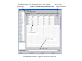
1
P&W Build-a-Model V2.0.1 Evaluation Release A User’s Manual
May 16, 2006
Pratt & Whitney
Build-a-Model
Parametric Simulation Environment
User’s Manual
V2.0.1
Evaluation Release A
May 16, 2006
This document is the property of Pratt & Whitney, and is delivered on the express
condition that it and the information contained in it are not to be used, disclosed, or
reproduced in whole or in part, for any purpose without the express written consent of
United Technologies Corporation; and that no right is granted to disclose or so use any
information contained in said document. These restrictions do not limit the right to use
information obtained from another source.
Pratt & Whitney Proprietary – Subject to Restrictions on Title Page
-i-
P&W Build-a-Model V2.0.1 Evaluation Release A User’s Manual
May 16, 2006
Contact Information:
Steve Sirica
Pratt & Whitney
tel: (860) 557-4781
e-mail: [email protected]
Igor Fuksman
Pratt & Whitney
tel: (860) 565-9612
e-mail: [email protected]
Pratt & Whitney Proprietary – Subject to Restrictions on Title Page
- ii -
P&W Build-a-Model V2.0.1 Evaluation Release A User’s Manual
May 16, 2006
Table of Contents
1
2
3
Introduction................................................................................................................. 1
Program Description ................................................................................................... 1
Program Setup............................................................................................................. 1
3.1
System Requirements.......................................................................................... 2
3.2
Installation........................................................................................................... 2
3.3
Cautions .............................................................................................................. 2
4
Panel Overview........................................................................................................... 3
4.1
Cycle Model........................................................................................................ 3
4.1.1
Configuration Panel .................................................................................... 3
4.1.2
Customer Interface...................................................................................... 3
4.1.3
User Variables............................................................................................. 4
4.1.4
Map Selection ............................................................................................. 4
4.1.5
Bleed Setup ................................................................................................. 4
4.1.6
Sub-System Schedules ................................................................................ 5
4.1.7
Custom Schedules....................................................................................... 5
4.1.8
Additional Schedules .................................................................................. 6
4.1.9
Calculators .................................................................................................. 6
4.1.10
Viewer Variable List................................................................................... 7
4.1.11
Additional Balances .................................................................................... 7
4.1.12
Design Point................................................................................................ 8
4.1.13
Design Sizer ................................................................................................ 8
4.1.14
Ratings/Limits............................................................................................. 9
4.1.15
Off Design................................................................................................. 10
4.2
Output Panel...................................................................................................... 11
4.3
Error Log Panel................................................................................................. 11
5
Advanced Features.................................................................................................... 11
5.1
File Printing ...................................................................................................... 11
5.2
Batch Operation ................................................................................................ 12
5.3
Subroutine Operation ........................................................................................ 12
Pratt & Whitney Proprietary – Subject to Restrictions on Title Page
- iii -
P&W Build-a-Model V2.0.1 Evaluation Release A User’s Manual
May 16, 2006
1 Introduction
Pratt & Whitney’s (P&W’s) Aircraft Build-a-Model parametric environment provides
steady-state & transient mathematical modeling of practically any air-breathing gas
turbine configuration. This release is targeted specifically for evaluation purposes to
solicit customer feedback on the general usage of this revolutionary parametric
simulation environment. This tool provides the user with a true parametric environment
offering greater flexibility then ever provided to users’ outside of P&W.
Three generalized sample models are provided as a means of demonstrating some of the
tool’s more typical capabilities. These models are generic and do not represent any
particular propulsion system. The three example models supplied are:
•
•
•
High Bypass Ratio Turbofan (turbofan_com.bam)
Low Bypass Ratio Turbofan (turbofan_mil.bam)
Turboshaft with Free Power Turbine (turboshaft.bam)
2 Program Description
Build-a-Model provides a generic parametric modeling system with a Graphical User
Interface. The GUI dynamically creates the necessary input for the underlying
Numerical Propulsion Simulation System (NPSS) and controls execution of the
simulation. Standard ARP5571 nomenclature is used to define applicable Input / Output
variables. The GUI automatically creates a display of the engine configuration and the
respective engine station numbering. Additionally, the GUI provides an interface to a
Model Tree, which displays a list of common input and output variables, including
names and descriptions, as well as switch settings and options. Variables can be
“dragged” from the Model Tree to any of the editable fields in the GUI panels and will
automatically contain the correct scope and case syntax.
3 Program Setup
The simulation can operate as a stand-alone program though use of the GUI, and can also
be configured to execute in batch mode or as a subroutine to a main program (only
recommended once Design Point has been set). For stand-alone GUI execution, once the
program is launched, simply open one of the supplied example files and modify /
populate the inputs. The user can also construct any supported configuration through the
use of the Configuration Panel interface and then populate the required inputs (this will
be discussed in the appropriate sections of the manual). Standard text output for detailed
thermodynamic performance is provided as well as options for Column Output and
Pratt & Whitney Proprietary – Subject to Restrictions on Title Page
-1-
P&W Build-a-Model V2.0.1 Evaluation Release A User’s Manual
May 16, 2006
Comma Separated Values. Details on customization of installation effects are covered
in detail later in this document.
Note that any changes made to inputs are not automatically saved. The example
configurations are read-only and are your reference baseline. After making changes to
input, simply go to File Save and name the session (extension should be .bam).
3.1 System Requirements
This tool is designed to operate on Windows NT, Windows 2000, and Windows XP.
Installation of Java Run Time library 1.4.2 is required for program execution. This run
time library is readily available for free download at www.sun.com. One additional file
is also required for execution, DFORMD.DLL – which is the Visual Fortran threaded
run-time support program. If this file is not on your system, it is available for free
download at www.hp.com.
3.2 Installation
Copy the entire contents of the CD to a folder of your choice. Once you have copied the
contents and verified that the additional required files are installed on your system (Java
Run Time library and Fortran DFORMD.DLL), edit the bam.bat file and modify the
following lines as required to match your system details.
rem Please set INST_TOP and GUI_JAVA during installation
rem - INST_TOP is full path to "bam_v2.0.1a" directory
rem - GUI_JAVA is full path to Java directory
set INST_TOP=K:\devl\share\npss\sim\mda\BAMevaluation\v2.0.1\bam_v2.0.1a
set GUI_JAVA=K:\test\wnt\java\j2sdk1.4.2\bin\java
After this is complete, go to the directory of your choice and execute bam.bat from a
command prompt. The simulation will operate from the folder it was executed in,
including all writing of output files.
3.3 Cautions
This parametric model is executing the underlying simulation system in an interactive
mode. As a result, once a variable is set, it does not return to the base value unless it is
explicitly reset. For example, consider the situation where the base Design Point is set
up with zero customer power extraction. If the user extracts power in the off-design
mode and then executes the Design Point without resetting the power extraction to OFF
or 0.0, this value will be retained and used in the subsequent Design Point calculations.
Note that the simulation can always be reinitialized by opening a saved .bam model.
Pratt & Whitney Proprietary – Subject to Restrictions on Title Page
-2-
P&W Build-a-Model V2.0.1 Evaluation Release A User’s Manual
May 16, 2006
During rare events where inputs are entered into the simulation that cause execution to
hang, it is sometimes necessary to kill the process. This is accomplished by going to
Windows Task Manager (Ctrl-Alt-Del) and ending the PEDWizart.nt.exe process.
After this it is safe to restart the model.
4 Panel Overview
The GUI environment consists of many interface panels. Many of these panels will never
need to be modified by the user after the initial setup and are used for detailed
customization of the underlying simulation. A high level description of each of these
panels is provided for reference.
4.1 Cycle Model
This panel contains a series of sub-panels that allow for complete definition and
execution of parametric engine model. They are described below.
4.1.1 Configuration Panel
This panel (Figure 1) displays the engine configuration as well as station identification.
Upon loading of an existing configuration (.bam), this panel is dynamically redefined.
This is also the interface where the user would create any supported configuration from
scratch. If you are creating a new configuration and already have an existing session
open, it is recommended that you use the File New menu before creating the new
configuration, otherwise not all of the Panels and Tabs will be reinitialized Next simply
use the drop-down menus to select the desired configuration and press Apply. This will
begin the process on building a new model. In the rare event that a desired configuration
is not available through the drop-down list, P&W can supply custom configuration files
that can be loaded through the custom configuration section.
4.1.2 Customer Interface
This panel (Figure 2) is generally used as a single point of input for the external
customer. In a typical parametric environment, the underlying simulation is more
complex than the general user would want to deal with. This interface provides a means
to set / modify values for Design and Design Sizing variables at a single location. These
variables can be accessed from anywhere in the model through the use of a Cint scope
(i.e. Cint.T041des). These variables are typically mapped to the appropriate sections
(parm_in = Cint.T041des).
Examples provided in this evaluation version provide complete flexibility with no
predefined / hardwired design rules. Typical Build-a-Model Parametric models supplied
to external customers will contain P&W specified design rules / criteria built-in and
require Design Sizing operation through the Customer Interface panel.
Pratt & Whitney Proprietary – Subject to Restrictions on Title Page
-3-
P&W Build-a-Model V2.0.1 Evaluation Release A User’s Manual
May 16, 2006
After entering the inputs in the Value column (remember to hit enter after typing /
pasting input), press the Apply button at the bottom of the panel. This will send the
information to the underlying simulation.
This panel also has an Import / Export type of capability through the use of the Save
and Open buttons. This provides a means to change this setup once it is delivered to
external user. The external user will have the ability to load modified inputs (which
include new Variables and modified Ranges).
4.1.3 User Variables
This panel (Figure 3) is for declaration of new variables for further use in the simulation.
These include the full complement of variable types in NPSS (real, integer, string) as
well as Independent and Dependent Balance variables. Declaration of variables in this
panel prevents the error of declaring same variable more than once.
When creating ad-hoc variables, it is recommended that this be done through the
Calculators panel. Additionally, it is recommended that user defined balances be done
through the Additional Balances panel. These respective panels provide a more user
friendly interface with added flexibility.
4.1.4 Map Selection
This panel (Figure 4) is used to select the appropriate component maps through the use of
drop-down lists. For this release, the selection is limited to the E3 compressor and
turbine maps that are provided in the NPSS release as well as generic examples for the
remaining components. It is possible to load new maps by typing the name of the map in
the appropriate drop-down section. Note that maps must adhere to the supported formats.
User supplied maps must end with a .runin extension and be stored in the \maps
subdirectory.
4.1.5 Bleed Setup
This panel (Figure 5) allows for the definition and configuration of pre-defined bleeds
and user defined bleeds. User defined bleeds are generally used for turbine cooling,
leakages, and other secondary flows. The user will need to define the appropriate
extraction and re-entry locations as well as work fractions and flow levels. Typical
Customer Bleed(s) and Stability Bleed(s) ports are automatically created. Specification
of Customer Bleed(s) (flow, % flow, or scheduled bleed) is handled through either
standard ARP5571 input or the Custom Schedules panel. Stability Bleed(s) is typically
defined through the appropriate Sub-Systems Schedules panel. There is also a FABL
sub-tab that allows for secondary flow definition using P&W methodology.
Pratt & Whitney Proprietary – Subject to Restrictions on Title Page
-4-
P&W Build-a-Model V2.0.1 Evaluation Release A User’s Manual
May 16, 2006
4.1.6 Sub-System Schedules
This panel (Figure 6) and the respective sub-panels are for detailed sub-system definition.
These effects typically include the following:
•
•
•
•
•
•
Shaft Parasitic Losses
Stability Bleed(s)
Fan Warpage
Heat Addition to Fuel
Variable Exhaust Nozzle Area Scheduling
Component Calibration
These sub-system effects can be defined either through populating the appropriate tables
or set through the use of a function. Note that the population of the independent variables
in the tables defaults to preconfigured drop-down lists but these variables can be overwritten with any available variable. If the function is defined to use a user supplied table,
this user defined table is input in the Data sub-tab and must adhere to NPSS table syntax.
When setting up these sub-systems, care should be paid to the selection of variables to
prevent a use-before-calculate situation.
There are two additional features available in this panel; Clear and Load. Pressing the
Clear button erases all inputs from table. The Load button allows for import of table
data from an external file. Note that the format of this file is very particular (examples
are provided on CD). The parser is still under development. Additionally, MS Excel
Copy / Paste features with Insert / Delete Row capability is under development and will
most likely negate the need for the Load feature.
4.1.7 Custom Schedules
This panel (Figure 7) contains the sub-panels that allow the customer to easily specify
custom installation effects. These effects include:
•
•
•
•
•
•
•
Inlet Recovery
Exhaust Nozzle Discharge Coefficient
Exhaust Nozzle Velocity Coefficient
Customer Bleed Flow
Customer Power Extraction
Heat Addition to Duct Flow
Installation Drag Coefficient
These sub-panels allow the user to set up a multi-variant table to specify the effect as well
as an equation (entered under function sub-tab). To specify that the simulation use the
table or function effects, set the respective switch (i.e. CpwrH.switchPwr = “CUSTOM”;)
Note that for single input values, it is not required to use these panels, simply specify the
value in the normal input manner (i.e. CpwrH.switchPwr = “INPUT”; CpwrH.Pwr_in =
75.0; specifies to extract 75 horsepower from the high-spool).
Pratt & Whitney Proprietary – Subject to Restrictions on Title Page
-5-
P&W Build-a-Model V2.0.1 Evaluation Release A User’s Manual
May 16, 2006
As with the Sub-System Schedules panel, there are two additional features available in
this panel; Clear and Load. Pressing the Clear button erases all inputs from table. The
Load button allows for import of table data from an external file. Note that the format of
this file is very particular (examples are provided on CD). The parser is still under
development. Additionally, MS Excel Copy / Paste features with Insert / Delete Row
capability is under development and will most likely negate the need for the Load
feature.
Similar to Sub-Systems Schedules, Custom Schedules can also be defined as a function
instead of a predefined table. Additionally, the function definition must be used if there
is a requirement to define 3D (and larger) tables as these are not currently supported via
the GUI table definition.
4.1.8 Additional Schedules
This panel (Figure 8) is a placeholder for anything that is not covered in the normal
panels and is entered in a free form input that adheres to NPSS syntax. Note that due to
the interactive parsing of the input, the /* … */ syntax for skipping blocks of input does
not work. The // prefix is required on every line that is to be skipped (no occurrence of
the /* format is allowed – even in a line that starts with //). It is possible to load and parse
a complete file through the use of the #include <yourfilename.ext> capability but this is
discouraged as the intention is for the .bam file to be fully self contained. Note that this
information applies to all free form input windows in Build-a-Model.
4.1.9 Calculators
This panel (Figure 9) allows for the creation of ad-hoc variables that are based on the
results of the simulation. These calculated parameters show up on the output under the
custom section when Custom Output option is turned on. There are four categories
available:
•
•
•
•
Corrected Parameter – allows for automatic calculation of corrected values
using theta and delta parameters
Compressor Efficiency – allows for combining compressors to calculate an
overall compressor efficiency
Turbine Efficiency – allows for combining of turbines to calculate an overall
turbine efficiency
Generic – allows for custom calculations
These variables can be accessed from anywhere in the simulation through the use of a
Cycle scope (i.e. Cycle.OPR).
Pratt & Whitney Proprietary – Subject to Restrictions on Title Page
-6-
P&W Build-a-Model V2.0.1 Evaluation Release A User’s Manual
4.1.10
May 16, 2006
Viewer Variable List
This panel (Figure 10) provides the user with the interface to define what variables are
output to Columns and Comma Separated Values. Initial list are dynamically created
based on selected configuration but can be modified. CSV output list is limited to 256
variables (MS Excel limitation). There is also an aliasing option to provide a customized
naming to the output (see example below). Aliasing is not required for every variable in
the list; they can be mixed and matched.
Name list without Alias (will show up in output as CmpH.WcIn)
"CmpH.WcIn",
Name list with Alias (will show up in output as W25R)
"CmpH.WcIn = W25R",
When a warning or limit is encountered during the execution of the simulation, the
default behavior for Column and CSV output is to mark the limited point with a + or *.
This automatic marking can be disabled with the following switch settings:
Disable Markings
ColumnOutput.showMark = FALSE;
CsvOutput.showMark = FALSE;
Enable Markings
ColumnOutput.showMark = TRUE;
CsvOutput.showMark = TRUE;
4.1.11
Additional Balances
This panel (Figure 11) is where user defined balances are defined. Note that when
defining a balance with this panel, it is not necessary to define the Independent and
Dependent in the User Variables panel. Balances can be defined as Always Active,
Active in Design Point, and Active Off-Design. Clicking the Check Box for the balance
will toggle the balance as active / deactive (you must press Apply after setting balance
up). Note that if a balance is active in the Design Point, it will also be active in the
Design Point defined through the Design Sizer.
When using a user defined balance that is active Off-Design, it is recommended that the
user provide guesses which are defined in functions. This is recommended to set
consistent guesses for every point and keep ensure simulation repeatability. This is
typically not required for balances that are active only in Design Point as these are
generally being set in the Design Point panel. Contact P&W if you have any questions
regarding this feature.
Pratt & Whitney Proprietary – Subject to Restrictions on Title Page
-7-
P&W Build-a-Model V2.0.1 Evaluation Release A User’s Manual
4.1.12
May 16, 2006
Design Point
This panel (Figure 12) establishes necessary information required to process design point.
Minimum required input is highlighted in green. The GUI Help menu contains a section
on Design Point inputs. Please review this section for more information regarding
required and optional design inputs.
Note that the settings for controlling the output can be specified on the Design Point
panel. These output options are either “OFF” or “ON”. The following outputs can be set
by user (these are located at the top of the panel).
•
•
•
•
•
•
•
•
viewer.switchSolverOutput
viewer.switchBasicOutput
viewer.switchReferenceOutput
viewer.switchBleedOutput
viewer.switchCustomOutput
viewer.switchColumnOutput
viewer.switchCsvOutput
viewer.switchUbinOutput
Controls Solver Output
Controls Typical Cycle Output
Controls Detailed Reference Output
Controls Detailed Bleed Output
Controls Custom Output (Calculators Panel)
Controls Column Output
Controls CSV Output
Controls Binary Output (binary file intended
for use with P&W internal tools)
Nested sweeping of variables is also set up on the Design Point panel in the Design
Matrix section. Typical use of this would be sweeping T4 and cycle pressure ratio
during Design Point. For an external release, Customer Interface variables are mapped
to this section and other appropriate balance settings. In this evaluation release, the user
would sweep Design Point input variables to accomplish this (i.e. Pset.parm_in,
CmpH.PRdes). This sweeping of variables can either be Inactive, Active in Design
Point, or Active with the Design Sizer.
4.1.13
Design Sizer
This panel (Figure 13) establishes the setup required for design and sizing of an engine
(Design and Off-Design) through the use of the Nested Solver. Examples of the use of
this panel are provided in the supplied models.
The user would define the settings for the specific points to be executed in this panel.
Additionally, there are Pre and Post Execute sections for further definition and control of
settings (these are optional and are not normally required). Pressing the up-arrow above
the Definition sub-tab reveals a free-form text input section. This allows for advanced
settings / input to the NPSS simulation. Pressing the down-arrow collapses this window.
This panel has a separate limit section that allows definition of constraints / limits as
applicable to the Nested Solver Sizing matrix.
It is recommended that the user set all inputs consistently in Off-Design sizer points due
to the interactive nature of this tool. For example, if an Off-Design sizing point has
Pratt & Whitney Proprietary – Subject to Restrictions on Title Page
-8-
P&W Build-a-Model V2.0.1 Evaluation Release A User’s Manual
May 16, 2006
power extraction and the Design Point does not, you must reset power extraction to
“OFF” for the Design Point.
There are two additional features on this panel; Save and Open. Save will write the
contents and settings of this panel to a file with a .bamsz extension. This file can then be
brought into another simulation with the Open feature. This can be very useful since
setting up the Sizing with the Nested Solver can be somewhat complex. A note of
caution on this usage is that one should limit the Importing of Sizing files to ones that
were created by an identical configuration. For example, if you Open / Load a Sizing file
that was created from a simulation that was a different configuration (Saved in 2-Spool
Turbofan, Opened in 1-Spool Turboshaft), since the module and station names for each
configuration are dynamically created, there is a high probability that the setup will be
incompatible between the two simulations.
4.1.14
Ratings/Limits
Single-Schedule Rating
Schedule 1
Input
Rating parameter
Rating parameter
This panel (Figure 14) controls the automatic rating definition and limit setup. The
following rating structures are available:
Double-Schedule, Double-Point Rating
Schedule 1
Schedule 2
Dynamic
Input
Break point 1-2
Schedule 1
Input
Schedule 2
Input
Break point 1-2
Rating parameter
Rating parameter
Break point not required
Double-Schedule Rating
Triple-Schedule Rating
Schedule 1
Input
Schedule 2
Input
Break point 1-2
Schedule 3
Input
Break point 2-3
The rating schedule inputs can be cross-referenced to the results of the Design Point and
the Design Sizer. In addition to running ratings, the program also allows the user to
specify percent rating. Normally, percent rating parameter should not be specified for
various IDLE ratings and for MINAB rating. Additionally, the percent rating parameter
should not be specified for MAXAB rating as well (in this case percent rating input is
used to specify augmentation level and is setup automatically).
Limits are not active during the dynamic rating creation and are applied off-design only.
There is a separate limit section available in the Design Sizer panel for constraining the
Nested Solver. Engineering Status Indicators (ESIs) are reported when a limit is
Pratt & Whitney Proprietary – Subject to Restrictions on Title Page
-9-
P&W Build-a-Model V2.0.1 Evaluation Release A User’s Manual
May 16, 2006
encountered. Generic Max Limit ESI is 70022503. Generic Min Limit ESI is 70012503.
Table Extrapolation Limit ESI is 71005101. Up to 10 ESIs can be added to Column and
CSV output using the following names (ESI0, ESI1, ESI2, ESI3, ESI4, ESI5, ESI6, ESI7,
ESI8, ESI9).
As with the Design Sizing panel, this panel has two additional features; Save and Open.
Save will write the contents and settings of this panel to a file with a .bamrl extension.
This file can then be brought into another simulation with the Open feature. This can be
very useful since setting up the Ratings and Limit structure can be somewhat complex.
One note of caution on this usage is that you should limit the Importing of Ratings /
Limits files to ones that were created by an identical configuration. For example, if you
Open / Load a Sizing file that was created from a simulation that was a different
configuration (Saved in 2-Spool Turbofan, Opened in 1-Spool Turboshaft), since the
module and station names for each configuration are dynamically created, there is a high
probability that the setup will be incompatible between the two simulations.
4.1.15
Off Design
This panel (Figure 15) is where the user specifies all of the off-design input. This input
adheres to ARP5571 structure and utilizes NPSS syntax. Note that it is possible to
specify the input in an external file and read that file in through this interface with the
following syntax:
#include <yourfilename.ext>
There are two additional sub-tabs available on this panel; For Loop and If Else. These
provide an interface for the user to populate ranges and by pressing the upper Apply
button this will write the required NPSS syntax to the free form text section at the cursor
location.
Users are encouraged to utilize the Model Tree drag-and-drop feature to avoid
typographical errors. All statements should be terminated with a semicolon (;) or the
program may crash (interactive mode waiting for end of input).
Occasionally some points may have difficulty converging. This difficulty can often be
overcome by running a successful point and stepping towards the desired target value
with small +/- increment (as applicable) after disabling the internal solver guesses (this
will effectively set the guess to “last point” values). This is accomplished with the
following settings:
Disables internal guess logic and uses last converged point as guess
Gcrv.switchGuess = "OFF";
After successful execution of point, remember to turn internal guess logic back on.
Enables internal guess logic
Gcrv.switchGuess = "ON";
Pratt & Whitney Proprietary – Subject to Restrictions on Title Page
- 10 -
P&W Build-a-Model V2.0.1 Evaluation Release A User’s Manual
May 16, 2006
4.2 Output Panel
This panel (Figure 16) contains the text output that is specified at execution (Basic,
Reference, Bleed, and Custom). It does not include the Comma Separated Values and
Column Output. CSV output gets written to separate .csv file (after Reset is pressed).
Column Output gets concatenated with output from the main Output Panel display to
.bamout file after Reset is pressed.
4.3 Error Log Panel
This panel (Figure 17) contains a running list of program errors, warnings, and limits
encountered during execution. It is only cleared upon re-opening of .bam simulation or
program restart.
5 Advanced Features
This section describes some of the advanced features available. These will not typically
be used by the general user.
5.1 File Printing
This feature is available through the Menu Print to File. Individual files or complete
simulation files can be printed. The individual file printing is useful when trying to
debug setup errors. Additionally, this feature can be used to capture the settings of a
particular functionality (i.e. bleed sub-system setup) and can be then brought into a full
NPSS external session. The Print All Files feature will write out complete contents of
simulation. This is required prior to batch and subroutine execution.
Due to the fact that some panels are dynamically populated (in particular Ratings / Limits
panel), the simulation must be executed once through the GUI prior to printing all files.
If this is not done, the contents of the dynamically populated panel files will not be
correct.
Design Point and / or Design Sizer files will be commented out in printed model (.mdl)
file if “Execute on Open” option is not selected on the Design Point / Design Sizer
panels. The user should either check the Execute on Open option on the respective
panel prior to printing or uncomment the files (remove //) in the model (.mdl) file.
Once the entire simulation is printed out for batch / subroutine mode execution, there is
no mechanism in place that prevents the user from modifying the resulting NPSS
simulation files. However, users are discouraged from updating the simulation in this
manner. The recommended procedure is to update the simulation through the GUI,
Pratt & Whitney Proprietary – Subject to Restrictions on Title Page
- 11 -
P&W Build-a-Model V2.0.1 Evaluation Release A User’s Manual
May 16, 2006
save the updated .bam file, and then re-print the entire simulation again. This way, the
.bam file contains the master copy and all generated results can be traced back to it.
5.2 Batch Operation
After writing all of the required simulation files out with the Print to File feature, you can
now execute the simulation from the command prompt in a batch mode without the GUI
active. One file that is created when you Print to File is called example.run. This file
contains the necessary instructions to operate in batch mode. Prior to program execution,
the proper environment variables will need to be set.
To set the proper environment variables, type the following command:
..... full path .....\bam.bat setenv
To launch the program in batch mode, type the following command:
PEDwizard.nt.exe example.run
Note that example.run contains the necessary inputs to run off-design. To change the offdesign inputs, either modify the off-design runin file or bring another file in by modifying
example.run contents.
5.3 Subroutine Operation
After writing all of the required simulation files out with the Print to File feature, you can
now link the simulation to another C++ or Fortran program and execute it in subroutine
mode. Examples of C++ (runcd1.c) and Fortran (runcd2.f) driver programs are supplied.
Instructions on subroutine mode are supplied in the subroutine_mode_readme.txt file, as
well as a Makefile which contains the appropriate compiler settings. As with operation in
batch mode, the proper environment variables will need to be set prior to program
execution.
To compile and link with a C++ program, use the following command (Makefile sets
appropriate compiler switches):
nmake /f Makefile.win32 runcd1
To compile and link with a FORTRAN program, use the following command (Makefile
sets appropriate compiler switches):
nmake /f Makefile.win32 runcd2
To set the proper environment variables prior to execution, type the following command:
..... full path .....\bam.bat setenv
Pratt & Whitney Proprietary – Subject to Restrictions on Title Page
- 12 -
P&W Build-a-Model V2.0.1 Evaluation Release A User’s Manual
May 16, 2006
Appendix A – Overview of Panels
Pratt & Whitney Proprietary – Subject to Restrictions on Title Page
- 13 -
P&W Build-a-Model V2.0.1 Evaluation Release A User’s Manual
Click to Make Tree Visible
May 16, 2006
Figure 1: Configuration Panel Overview
Model Tree
Check to Execute Design Point
Check to Execute Design Sizer
Check to Execute Off-Design
(also executes Design Point)
Pratt & Whitney Proprietary – Subject to Restrictions on Title Page
- 14 -
P&W Build-a-Model V2.0.1 Evaluation Release A User’s Manual
Variable Name
Figure 2: Customer Interface Panel Overview
May 16, 2006
Variable Description
Set Value Here
Remember Apply
Pratt & Whitney Proprietary – Subject to Restrictions on Title Page
- 15 -
P&W Build-a-Model V2.0.1 Evaluation Release A User’s Manual
May 16, 2006
Figure 3: User Variables Panel Overview
Pratt & Whitney Proprietary – Subject to Restrictions on Title Page
- 16 -
P&W Build-a-Model V2.0.1 Evaluation Release A User’s Manual
May 16, 2006
Figure 4: Map Selection Panel Overview
Pratt & Whitney Proprietary – Subject to Restrictions on Title Page
- 17 -
P&W Build-a-Model V2.0.1 Evaluation Release A User’s Manual
May 16, 2006
Figure 5: Bleed Setup Panel Overview
Pratt & Whitney Proprietary – Subject to Restrictions on Title Page
- 18 -
P&W Build-a-Model V2.0.1 Evaluation Release A User’s Manual
May 16, 2006
Figure 6: Sub-System Schedules Panel Overview
Drop-Down List
(can be over-written)
Table or Function
Select Table or Function
Pratt & Whitney Proprietary – Subject to Restrictions on Title Page
- 19 -
P&W Build-a-Model V2.0.1 Evaluation Release A User’s Manual
Select Installation Effect Panel
May 16, 2006
Figure 7: Custom Schedules Panel Overview
Populate Table
Can use Drop Down or Type In Variable
Select Table or Function (equation) Option
Pratt & Whitney Proprietary – Subject to Restrictions on Title Page
- 20 -
P&W Build-a-Model V2.0.1 Evaluation Release A User’s Manual
May 16, 2006
Figure 8: Additional Schedules Panel Overview
Pratt & Whitney Proprietary – Subject to Restrictions on Title Page
- 21 -
P&W Build-a-Model V2.0.1 Evaluation Release A User’s Manual
Figure 9: Calculators Panel Overview
May 16, 2006
Create New Ad-Hoc Variables Here
output represents final variable
displayed on output page
Pratt & Whitney Proprietary – Subject to Restrictions on Title Page
- 22 -
P&W Build-a-Model V2.0.1 Evaluation Release A User’s Manual
May 16, 2006
Figure 10: Viewer Variable List Panel
Comma Separated Values List
Column Output List
Customize Variable List Here
Pratt & Whitney Proprietary – Subject to Restrictions on Title Page
- 23 -
P&W Build-a-Model V2.0.1 Evaluation Release A User’s Manual
May 16, 2006
Figure 11: Additional Balances Panel Overview
Pratt & Whitney Proprietary – Subject to Restrictions on Title Page
- 24 -
P&W Build-a-Model V2.0.1 Evaluation Release A User’s Manual
Figure 12: Design Point Panel Overview
May 16, 2006
Set Output Options Here
Set Parametric Sweep Variables Here
Pratt & Whitney Proprietary – Subject to Restrictions on Title Page
- 25 -
P&W Build-a-Model V2.0.1 Evaluation Release A User’s Manual
Select Points to Set Titles
Figure 13: Design Sizer Panel Overview
May 16, 2006
Set Title Here
Pratt & Whitney Proprietary – Subject to Restrictions on Title Page
- 26 -
P&W Build-a-Model V2.0.1 Evaluation Release A User’s Manual
May 16, 2006
Figure 14: Ratings and Limits Panel Overview
Pratt & Whitney Proprietary – Subject to Restrictions on Title Page
- 27 -
P&W Build-a-Model V2.0.1 Evaluation Release A User’s Manual
Figure 15: Off-Design Panel Overview
May 16, 2006
Use to Simplify Nesting of Variables
Variables in Model Tree
Variable Description
Off-Design Input
can also use
#include <yourfile.ext>
Pratt & Whitney Proprietary – Subject to Restrictions on Title Page
- 28 -
P&W Build-a-Model V2.0.1 Evaluation Release A User’s Manual
May 16, 2006
Figure 16: Output Panel Overview
Pressing Reset Clears Output Panel Screen
User Defined Output File Name Here (default is untitled.bamout)
Contents of Output Get Written to File When Reset is Pressed
Pratt & Whitney Proprietary – Subject to Restrictions on Title Page
- 29 -
P&W Build-a-Model V2.0.1 Evaluation Release A User’s Manual
May 16, 2006
Figure 17: Error Log Panel Overview
Program Errors, Warnings, and Limits are Reported Here
Note: Limits are also reported in Output Panel
Pratt & Whitney Proprietary – Subject to Restrictions on Title Page
- 30 -
P&W Build-a-Model V2.0.1 Evaluation Release A User’s Manual
May 16, 2006
Intentionally Left Blank
Pratt & Whitney Proprietary – Subject to Restrictions on Title Page
- 31 -