1
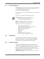
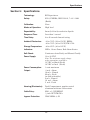
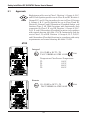
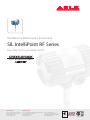
Installation & Maintenance Instructions
SIL IntelliPoint RF Series
Two-Wire, Point Level Safety Switch
Reading Office
Aberdeen Office
Cutbush Park, Danehill, Lower Earley,
Reading, Berkshire. RG6 4UT. UK.
Tel: +44 (0)118 9311188
Email: [email protected]
Unit 6 Airside Business Park, Kirkhill Industrial Estate,
Dyce, Aberdeen. AB21 0GT. UK.
Tel: +44 (0)1224 725999
Email: [email protected]
Internet: www.able.co.uk
e-procurement: www.247able.com
Registered in England No: 01851002
VAT No: GB 417 2481 61
Leader in
Level Measurement
Technical Assistance: 1-800-527-6297
Outside North America: +1-215-674-1234
Installation and
Operating Instructions
SIL IntelliPoint RF Series
Two-Wire, Point Level Safety Switch
U.S. and Canada:
1-800-553-9092
24-Hour Service:
1-800-527-6297
International:
+1 215-674-1234
Fax:
+1 215-674-2731
E-mail:
[email protected]
Website:
www.drexelbrook.com
AMETEK Drexelbrook makes no warranty of any kind with regard to the material contained
in this manual, including, but not limited to, implied warranties or fitness for a particular
purpose. Drexelbrook shall not be liable for errors contained herein or for incidental or
consequential damages in connection with the performance or use of material.
© AMETEK Drexelbrook
EDO# 03-10-100
SXRNTXX-LM
Issue# 11
SIL IntelliPoint RF Series
Two-Wire, Point Level, Safety, Switch
Extend your warranty!
...from 12 months to 36 months by
registering your purchase. Please
go to www.drexelbrook.com.
Click on "Contact Us"
then"Warranty Registration"
and fill out the form.
Contents
Contents
Section 1:
1.1
1.2
1.3
1.4
Introduction.................................................................................................1
System Description.......................................................................................1
Technology....................................................................................................1
Model Number..............................................................................................2
Dual Compartment Housing Detail...............................................................4
Section 2:
2.1
2.2
2.2.1
2.3
2.4
2.5
2.6
2.7
Installation...................................................................................................5
Unpacking.....................................................................................................5
Mounting and Installation Guidelines............................................................5
Installation of Flush-Mounted Sensing Elements..........................................8
Input Wiring...................................................................................................8
Spark Protection ..........................................................................................9
Circuit Board ................................................................................................9
Output & Status LEDs...................................................................................13
Sensing Element Connection........................................................................14
Section 3: Spare Parts List...........................................................................................16
Section 4:
4.1
4.2
4.3
4.4
4.5
4.6
4.7
4.8
4.9
4.10
4.11
Troubleshooting..........................................................................................17
Testing Sensing Element..............................................................................17
Testing Electronic Unit..................................................................................18
Over Range...................................................................................................19
Under Range.................................................................................................19
Testing Integral Cable...................................................................................19
Testing Remote Cable...................................................................................20
Testing Power Supply....................................................................................20
Factory Assistance........................................................................................21
Field Service.................................................................................................21
Customer Training.........................................................................................21
Equipment Return.........................................................................................22
Section 5: Specifications..............................................................................................23
5.1
Approvals......................................................................................................24
Section 6:
6.1
6.2
6.3
6.4
6.5
6.6
Control Drawings........................................................................................27
FM Control Drawings....................................................................................27
NEMKO / ATEX Control Drawings................................................................42
CSA Control Drawings..................................................................................49
Mounting and Wiring for Spark Protector Drawings......................................58
Adding a Padded Capacitor..........................................................................61
Dual Seal Assembly for 700 Series Sensing Elements................................64
Appendix A:SIL Declaration of Conformity...................................................................A1
Appendix B:CE Mark Declaration of Conformity...........................................................B1
Management summary
This report summarizes the results of the Failure Modes, Effects, and Diagnostic Analysis
(FMEDA) of the Safety IntelliPoint RF™ Series Point Level Switch. A Failure Modes, Effects,
and Diagnostic Analysis is one of the steps to be taken to achieve functional safety certification
per IEC 61508 of a device. From the FMEDA, failure rates and Safe Failure Fraction are
determined. The FMEDA that is described in this report concerns only the hardware of the
Safety IntelliPoint RF™ Series Point Level Switch, electronic and mechanical, including the
probe assembly. For full functional safety certification purposes all requirements of IEC 61508
must be considered.
The Safety IntelliPoint RF™ Series Point Level Switch is a two-wire, 4 – 20 mA smart device
with discrete output levels. It contains self-diagnostics and is programmed to send it’s output a
specified state upon internal detection of a failure. For safety instrumented systems usage it is
assumed that the 4 – 20 mA output is used as the primary safety variable. All other possible
output variants are not covered by this report. The different devices can be equipped with or
without display.
The Safety IntelliPoint RF™ Series Point Level Switch is classified as a Type B1 device
according to IEC61508, having a hardware fault tolerance of 0. The analysis shows that the
device has a safe failure fraction between 90 and 99% (assuming that the logic solver is
programmed to detect any currents outside the discrete output levels boundaries, see section
4.4) and therefore may be used up to SIL 2 as a single device.
The FMEDA analysis was performed for the High Level Fail Safe setting of the switch (HLFS).
Table 1 lists the failure rates for the Safety IntelliPoint RF™ Series Point Level Switch according
to IEC 61508, assuming that the logic solver is set to detect any currents outside a 1mA range
around the three output levels.
Table 1: Failure rates according to IEC 61508
Safety IntelliPoint RF™ Series
Point Level Switch
λsd
λsu2
λdd
λdu
SFF
High Level Fail Safe application
0 FIT
300 FIT
686 FIT
73 FIT
93.2%
These failure rates are valid for the useful lifetime of the product, see Appendix A.
A user of the Safety IntelliPoint RF™ Series Point Level Switch can utilize these failure rates in
a probabilistic model of a safety instrumented function (SIF) to determine suitability in part for
safety instrumented system (SIS) usage in a particular safety integrity level (SIL). A full set of
failure rates is presented in section 4.5 along with all assumptions.
1
Type B component: “Complex” component (using micro controllers or programmable logic); for details
see 7.4.3.1.3 of IEC 61508-2.
2
It is important to realize that the No Effect failures and Annunciation Undetected failures are included in
the “safe” failure category according to IEC 61508. Note that these failures will not affect system reliability
or safety and should not be included in spurious trip calculations
© exida.com L.L.C.
William M. Goble – John C. Grebe
ame 04-05-15 r001 v1 r11 safety intellipoint_, 7/27/2004
Page 2 of 16
Introduction
Section 1: Introduction
1.1
System Description
The AMETEK Drexelbrook IntelliPoint™ Series uses No‑Cal™
technology to detect the presence or absence of material without
calibration or initiation via setpoint adjustments, push-buttons,
or magnets.
k air
d
C
A
d
k air
C
A
k media
kmedia
kA
C= d
kA
C = d
Figure 1-1
Simple Capacitance Probe
(Insulating Media Shown)
1.2
Installation is simple and easy. Simply apply power and the
IntelliPoint system is ready to detect the presence or absence
of material. Since the IntelliPoint instrument does not require
calibration or setpoint adjustments, it is capable of operating
in non-dedicated tanks regardless of the material being
measured.
Notice: Material to be Measured Must Be Below
Sensor when Power is Applied.
The AutoVerify™ self-testing function continuously monitors
the entire system to ensure proper operation. Manual Certify™
changes the outputs in order to test the loop current and ensure
proper operation of the control systems.
Technology
In a simple capacitance probe-type sensing element, when
the level rises and material covers the probe, the capacitance
within the circuit between the probe and the media (conductive
applications) or the probe and the vessel wall (insulating
applications) increases. This is due to the dielectric constant
(k) of the material, which causes a bridge mis-balance. The
signal is demodulated (rectified), amplified, and the output is
increased. There are drawbacks, however, especially when
there is coating of the probe.
Figure 1-2
RF Admittance Probe
with Cote-Shield
An RF Admittance level transmitter is the next generation.
Although similar to the capacitance concept, IntelliPoint
employs a radio frequency signal and adds the Cote-Shield™
circuitry within the Electronics Unit.
This patented Cote-Shield™ circuitry is designed into the
IntelliPoint series and enables the instrument to ignore the
effect of buildup or material coating on the sensing element. The
sensing element is mounted in the vessel and provides a change
in RF admittance indicating presence or absence of material.
The Cote-Shield element of the sensor prevents the
transmission of RF current through the coating on the sensing
element. The only path to ground available for the RF current
is through the material being measured.
The result is an accurate measurement regardless of the amount
of coating on the probe, making it by far the most versatile
technology, good for very wide range conditions from cryogenics
to high temperature, from vacuum to 10,000psi pressure, and
works with all types of materials.
1
Safety IntelliPoint RF, SXRNTXX Series User's Manual
1.3
Model Number
SXRNTX
Safety IntelliPoint RF TM
Safety Switch
S
SIL
1
2
SIL1
SIL2
Technology
R
RF Admittance
Measurement Type
L
No Calib., 2 pF Fixed Preload
Input
T
Two Wire Power Supply 13-30 VDC
Housing
0
1
2
3
4
5
6
7
8
9
A
B
C
No Approvals, NEMA 4X/IP66, M20 X 1.5 conduit entries
No Approvals, NEMA 4X/IP66, ¾” NPT conduit entries
ATEX Approved, NEMA 4X/IP66, M20 X 1.5 conduit entries
FM Approved, NEMA 4X/IP66, ¾” NPT conduit entries
CSA Approved, NEMA 4X/IP66, ¾” NPT conduit entries
No Approvals, NEMA 4X/IP66, M20 X 1.5 conduit entries, Dual Seal, Perm-a-Seal sensors – only
No Approvals, NEMA 4X/IP66, ¾” NPT conduit entries, Dual Seal, Perm-a-Seal sensors – only
FM Approved, NEMA 4X/IP66, ¾” NPT conduit entries, Dual Seal, Perm-a-Seal sensors – only
CSA Approved, NEMA 4X/IP66, ¾” NPT conduit entries, Dual Seal, Perm-a-Seal sensors – only
No Approvals, NEMA 4X/IP66, M20 X 1.5 conduit entries, Dual Seal, Non Perm-a-Seal sensors – only
No Approvals, NEMA 4X/IP66, ¾” NPT conduit entries, Dual Seal, Non Perm-a-Seal sensors – only
FM Approved, NEMA 4X/IP66, ¾” NPT conduit entries, Dual Seal, Non Perm-a-Seal sensors – only
CSA Approved, NEMA 4X/IP66, ¾” NPT conduit entries, Dual Seal, Non Perm-a-Seal sensors – only
Electronics
0
Integral
1
Remote, no cable
2
Rmt. w/ 3 m (10 ft.) G.P. Cable
3
Rmt. w/ 7.6 m (25 ft.) G.P. Cable
4
Rmt. w/ 10.6 m (35 ft.) G.P. Cable
5
Rmt. w/ 15.2 m (50 ft.) G.P. Cable
6
Rmt. w/ 23 m (75 ft.) G.P. Cable
7
8
9
A
B
C
D
Rmt. w/ (25 ft.) Tri-Ax Cable
Rmt. w/ (50 ft.) Tri-Ax Cable
Rmt. w/ (75 ft.) Tri-Ax Cable
Rmt. w/ (10 ft.) Hi-Temp. Cable
Rmt. w/ (25 ft.) 1st 10ft Hi-Temp. Cbl.
Rmt. w/ (35 ft.) 1st 10ft Hi-Temp. Cbl.
Rmt. w/ (50 ft.) 1st 10ft Hi-Temp. Cbl.
E
F
G
H
J
K
Rmt. w/ (75 ft.) 1st 10ft Hi-Temp. Cbl.
Rmt. w/ (5 ft.) G.P. Cable
Rmt. w/ (5 ft.) Tri-Ax Cable
Rmt. w/ (10 ft.) Tri-Ax Cable
Rmt. w/ (35 ft.) Tri-Ax Cable
Rmt. w/ (5 ft.) Hi-Temp. Cable
Output
0
8-16mA Output
Sensing Element
Application
00 General purpose
01
02
03
04
06
07
09
10
11
12
13
14
15
16
Continued on Next Page
17
18
19
Sensing Element
700-1202-001 remote
700-1202-021 integral
700-1202-012 remote
700-1202-022 integral
Pressure/Temperature
13.8 bar @ 232°C (200 PSI @ 450°F)
Wetted Parts
316SS and PEEK
Floating roof with
cable attachment
and brass bottom weight
General purpose,
700-1202-014 remote
longer insertion lengths
700-1202-024 integral
with cable attachment
and 316SS bottom weight
Proximity
700-1202-018 remote
700-1202-028 integral
13.8 bar @ 177°C (200 PSI @ 350°F)
316SS, Brass,
and PEEK
13.8 bar @ 177°C (200 PSI @ 350°F)
316SS and PEEK
13.8 bar @ 232°C (200 PSI @ 450°F)
General purpose,
high temperature
and pressure
General purpose with
FDA approved
materials of construction
General purpose
Granular materials
General purpose
Granular materials with
FDA approved
materials of construction
Corrosive liquids (2)(4)(9)
General purpose,
higher pressure
TFE compatibility required
Corrosive material,
higher pressure
Sanitary (3)
700-1202-041 remote
700-1202-042 integral
69 bar @ 121°C (1000 PSI @ 250°F)
20.7 bar @ 232°C (300 PSI @ 450°F)
316SS and PEEK
with 76 mm (3)
316SS proximity plate
316SS and PEEK
700-1202-031 remote
700-1202-032 integral
13.8 bar @ 232°C (200 PSI @ 450°F)
316SS and FDA grade
PEEK
700-1202-010 remote
700-1202-020 integral
700-1202-033 remote
700-1202-034 integral
13.8 bar @ 232°C (200 PSI @ 450°F)
316SS and PEEK with
7/8 inch dia. 316SS collar
316SS and FDA grade
PEEK with 7/8 inch dia.
316SS collar
700-0001-018 remote
700-0201-005 int/rem
3.4 bar @ 149°C (50 PSI @ 300°F)
69 bar @ 38°C (1000 PSI @ 100°F)
13.8 bar @ 232°C (200 PSI @ 450°F)
PFA
316SS and TFE
700-0201-005 int/rem
Hastelloy C
700-0201-036 int/rem
Hastelloy C and TFE
General Purpose,
low pressure
Heavy duty, agitated
tanks or material
with high bulk density (1)
High Integrity Seal for
Hazardous Materials
Sanitary (3) lowpressure
Corrosive material,
higher pressure with
waterlike viscosity (4)
Interface Measurement
700-0202-002 int/rem
69 bar @ 38°C (1000 PSI @ 100°F)
13.8 bar @ 232°C (200 PSI @ 450°F)
69 bar @ 38°C (1000 PSI @ 100°F)
13.8 bar @ 232°C (200 PSI @ 300°F)
3.4 bar @ 149°C (50 PSI @ 300°F)
1.4 bar @ 232°C (20 PSI @ 450°F)
69 bar @ 38°C (1000 PSI @ 100°F)
13.8 bar @ 232°C (200 PSI @ 450°F)
700-0202-043 remote
316SS and TFE
34.5 bar @ 149°C (500 PSI @ 300°F)
PFA
700-0202-036 int/rem
700-0001-022 int/rem
3.4 bar @ 149°C (50 PSI @ 300°F)
69 bar @ 38°C (1000 PSI @ 100°F)
34.5 bar @ 149°C (500 PSI @ 300°F)
316SS and TFE
TFE
700-0002-023 int/rem
69 bar @ 38°C (1000 PSI @ 100°F)
34.5 bar @ 149°C (500 PSI @ 300°F)
6.9 bar @ 121°C (100 PSI @ 250°F)
0 bar @ 232°C (0 PSI @ 450°F)
316SS and TFE
Miniature Pilot
700-0209-002 remote
Plant Sensor (1)(7)
High Pressure / High Temperature
60 High Pressure & Temp.
700-0204-038 remote
2
High Temperature
700-0204-002 remote
High Pressure & Temp.
700-0204-048 remote
Sensing Element Not Listed
CSL
316 SS and TFE
137.9 bar @ 93°C (2000 PSI @ 200°F) 316SS and Ceramic
68.9 bar @ 260°C (1000 PSI @ 500°F)
0 bar @ 816°C (0 PSI @ 1500°F)
316SS and Ceramic
275.8 bar @316°C (4000 PSI @ 600°F) 316SS
Mounting Type (See separate Mounting Chart for first three digits)
IL
316/316L SS and TFE
316SS and TFE
700-0002-360 int/rem
20
61
62
ZZ
13.8 bar @ 232°C (200 PSI @ 450°F)
10
11
12
13
1.3
Granular materials with
FDA approved
materials of construction
Corrosive liquids (2)(4)(9)
General purpose,
higher pressure
TFE compatibility required
Corrosive material,
higher pressure
Sanitary (3)
700-1202-034 integral
700-0001-018 remote
700-0201-005 int/rem
3.4 bar @ 149°C (50 PSI @ 300°F)
69 bar @ 38°C (1000 PSI @ 100°F)
13.8 bar @ 232°C (200 PSI @ 450°F)
PFA
316SS and TFE
700-0201-005 int/rem
Hastelloy C
700-0201-036 int/rem
69 bar @ 38°C (1000 PSI @ 100°F)
13.8 bar @ 232°C (200 PSI @ 450°F)
69 bar @ 38°C (1000 PSI @ 100°F)
13.8 bar @ 232°C (200 PSI @ 300°F)
3.4 bar @ 149°C (50 PSI @ 300°F)
1.4 bar @ 232°C (20 PSI @ 450°F)
69 bar @ 38°C (1000 PSI @ 100°F)
13.8 bar @ 232°C (200 PSI @ 450°F)
Hastelloy C and TFE
700-0002-360 int/rem
34.5 bar @ 149°C (500 PSI @ 300°F)
PFA
700-0202-036 int/rem
700-0001-022 int/rem
3.4 bar @ 149°C (50 PSI @ 300°F)
69 bar @ 38°C (1000 PSI @ 100°F)
34.5 bar @ 149°C (500 PSI @ 300°F)
316SS and TFE
TFE
700-0002-023 int/rem
69 bar @ 38°C (1000 PSI @ 100°F)
34.5 bar @ 149°C (500 PSI @ 300°F)
6.9 bar @ 121°C (100 PSI @ 250°F)
0 bar @ 232°C (0 PSI @ 450°F)
316SS and TFE
Model Number (Continued)
14
Continued from Previous Page
15
16
17
18
19
General Purpose,
low pressure
Heavy duty, agitated
tanks or material
with high bulk density (1)
High Integrity Seal for
Hazardous Materials
Sanitary (3) lowpressure
Corrosive material,
higher pressure with
waterlike viscosity (4)
Interface Measurement
700-0202-002 int/rem
700-0202-043 remote
20
Miniature Pilot
700-0209-002 remote
Plant Sensor (1)(7)
High Pressure / High Temperature
60 High Pressure & Temp.
700-0204-038 remote
61
62
ZZ
PEEK with 7/8 inch dia.
316SS collar
High Temperature
700-0204-002 remote
High Pressure & Temp.
700-0204-048 remote
Sensing Element Not Listed
316/316L SS and TFE
316SS and TFE
316SS and TFE
316 SS and TFE
137.9 bar @ 93°C (2000 PSI @ 200°F) 316SS and Ceramic
68.9 bar @ 260°C (1000 PSI @ 500°F)
0 bar @ 816°C (0 PSI @ 1500°F)
316SS and Ceramic
275.8 bar @316°C (4000 PSI @ 600°F) 316SS
Mounting Type (See separate Mounting Chart for first three digits)
xxxH
xxxJ
xxxK
xxxL
P00X
xxxZ
S
IL
914 mm (36")
914 mm (36")
1219 mm (48")
1524 mm (60")
IL/CSL Other
Other
CSL
254 mm (10")
0 mm (0")
254 mm (10")
254 mm (10")
Notes: CSL (Cote-Shield Length) should extend through Nozzle + Typical "Wall Buildup" + 2 Inches
(1) Available with remote electronics only
(6) Use A1B mounting option
(2) Use A1P mounting option
(7) Use A8B mounting option (¼-inch NPT)
(3) Choose only sanitary mounting options
(8) Choose from flange mounting only
IMPORTANT:
Minimum Active Length for SIL Compliance is 24" (610mm)
(4) Available with 0-inch CSL only
(9) FM approved with remote electronics only
Consult Factory for Shorter Lengths
(5) Use P00X mounting option
R
T
0
Not all mounting options are available with all sensing elements
NPT Threads
A1B ¾"NPT
A1C ¾"NPT
A1P ¾"NPT
DIN Flanges
E01 25 mm
EP1 25 mm
EQ1 50 mm
ER1 50 mm
ES1 80 mm
ET1 80 mm
EU1 100 mm
EV1 100 mm
EW1 150 mm
EX1 150 mm
316SS
Hastelloy C
PFA
16 bar
40 bar
16 bar
40 bar
16 bar
40 bar
16 bar
40 bar
16 bar
40 bar
RF 316/316L SS
RF 316/316L SS
RF 316/316L SS
RF 316/316L SS
RF 316/316L SS
RF 316/316L SS
RF 316/316L SS
RF 316/316L SS
RF 316/316L SS
RF 316/316L SS
A2B
A2C
E02
EP2
EQ2
ER2
ES2
ET2
EU2
EV2
EW2
EX2
1"NPT
1"NPT
25 mm
25 mm
50 mm
50 mm
80 mm
80 mm
100 mm
100 mm
150 mm
150 mm
316SS
Hastelloy C
16 bar
40 bar
16 bar
40 bar
16 bar
40 bar
16 bar
40 bar
16 bar
40 bar
RF CS
RF CS
RF CS
RF CS
RF CS
RF CS
RF CS
RF CS
RF CS
RF CS
Sanitary TriClamps
C2B 1"TriClamp
C3B 1½"TriClamp
ANSI Flanges
DA1 1"
150#
DB1 1½" 150#
DC1 2"
150#
DD1 2½" 150#
DE1 1"
300#
DF1 1½" 300#
DG1 2"
300#
DH1 2½" 300#
DI1 3"
150#
DJ1 3"
300#
DK1 4"
150#
DL1 4"
300#
DM1 6"
150#
DN1 6"
300#
3
316SS
316SS
C4B
RF 316/316L SS
RF 316/316L SS
RF 316/316L SS
RF 316/316L SS
RF 316/316L SS
RF 316/316L SS
RF 316/316L SS
RF 316/316L SS
RF 316/316L SS
RF 316/316L SS
RF 316/316L SS
RF 316/316L SS
RF 316/316L SS
RF 316/316L SS
2"TriClamp
DA2
DB2
DC2
DD2
DE2
DF2
DG2
DH2
DI2
DJ2
DK2
DL2
DM2
DN2
1"
1½"
2"
2½"
1"
1½"
2"
2½"
3"
3"
4"
4"
6"
6"
316SS
150#
150#
150#
150#
300#
300#
300#
300#
150#
300#
150#
300#
150#
300#
RF CS
RF CS
RF CS
RF CS
RF CS
RF CS
RF CS
RF CS
RF CS
RF CS
RF CS
RF CS
RF CS
RF CS
Introduction
Safety IntelliPoint RF, SXRNTXX Series User's Manual
1.4
Dual Compartment Housing Detail
Conduit Entries (2)
¾-inch NPT (FM/CSA Systems)
M20 x 1.5 (CENELEC Systems)
Input and Output Module
LABEL
(see below)
114 mm
(4.5 inches)
140 mm
(5.5 inches)
External
Tag Loop (2)
Sensing Element
and
Circuit Board
External Lid Lock (2)
M4 2.5 mm Hex Drive
Equipotential Connection
165 mm (6.5 inches)
Locked
Unlocked
Lid Locking
Mechanism
(CENELEC Systems)
Figure 1-3
Dual Compartment Housing Detail
The Input/Output Module (IOM) is located on
Customer Connection side; sensing element/circuit
board are on opposite side.
4
Installation
Section 2: Installation
2.1
Unpacking
Carefully remove the contents of the shipping carton and check
each item against the packing list before destroying any packing
material. If there is any shortage or damage, report it to the
factory immediately.
2.2
Mounting and Installation Guidelines
CAUTION:
The IntelliPoint RF instrument must be powered AFTER it
is installed in the application and with material BELOW the
sensing element.
The IntelliPoint RF instrument can be mounted vertically or
horizontally at any angle. The mounting location should be as
free as possible from vibration, corrosive atmospheres, and any
possibility of mechanical damage. Ambient temperatures at
electronics should be between -30°C to 70°C (-22°F to 158°F).
The IntelliPoint RF instrument uses a dual compartment
housing and a completely encapsulated input/output module
to reduce the possibility that damage may occur from water
migrating into the housing through the conduit. To further
reduce the possibility of damage caused by water in the conduit,
install a drip loop and breather drain to purge any accumulating
moisture. See to Figure 2-1.
Figure 2-1
Recommended Conduit Connection
5
Safety IntelliPoint RF, SXRNTXX Series User's Manual
2.2
Mounting and Installation Guidelines (Continued)
After system is installed and level is below sensing element,
apply power. The RF Series instrument does not require any
calibration or setpoint adjustments and is ready to detect change
in level. If properly installed, the green LED lights when power
is applied. The Red LED should not be flashing. If the Red LED
is flashing, refer to Section 4: Troubleshooting.
Cable fittings supplied are weather-resistant.
They are NOT certified as explosion-proof (XP)
or flameproof (d) unless they are specifically
marked.
The IntelliPoint RF instrument is rated Intrinsically
Safe (I.S.) when power is provided from an I.S.
supply.
WARNING:
IntelliPoint RF equipment is rated explosion-proof. When
installing in explosion hazardous areas [rated “potentially
hazardous” (EU) or “hazardous classified” (USA)] observe all
national and local regulations as well as specifications in the
certificate.
Mount sensing element using the following installation
guidelines. See Figure 2-2.
When installing IntelliPoint RF instrument, ambient
temperature at electronics must not exceed 70°C (158°F).
When installing flange-mounted sensing elements, keep mating
surfaces and bolts free of paint and corrosion to ensure proper
electrical contact with vessel. Avoid using excessive amounts of
Teflon™ tape when installing threaded sensing elements.
Install systems with threaded NPT connection via wrench flats
on the process connection ONLY.
Locate sensing element to avoid enhancing electrostatic
discharge from process medium, as is good practice with any
thermowell, displacer, or sampler. This includes correct bonding
to the tank or silo wall.
If installation area is rated explosion-proof and requires conduit
seal fittings, they should be used in accordance with company
standards and local codes.
6
Installation
2.2
Mounting and Installation Guidelines (Continued)
Mounting sensing element inside a pipe is not recommended.
Do not mount a Cote-Shield sensing element through a nozzle
that exceeds length of first insulator.
Ensure that there are no obstructions or agitator blades to
interfere with sensing element.
Rigid sensing elements can be mounted either vertically or
horizontally.
Do Not Shorten the sensing element without
checking with the factory. 1-800-527-6297 or
215‑674-1234
After the system has been installed, a function test
(See Section 4.2) should be performed.
Figure 2-2
Installation Considerations
A full system function check (See Section 4.2) should
be performed when:
• Any system component is changed or replaced by the user.
• Any system component is modified by the user.
7
Safety IntelliPoint RF, SXRNTXX Series User's Manual
2.2.1
Installation of Flush-Mounted Sensing Elements
These instructions apply to all flush on/off sensing elements,
models 700-0207-001, 700-0207-002, 700-0207-003, 700-0207004, 700-0207-006. These systems will sense presence of
material (no flow or plugged chute) and absence of material
(flow or empty chute) at the sensing element. The Flush Sensing
Element will ignore free falling material.
Sensing Element at the Top of a Chute.
• The flush sensing element should be mounted In
The Flow Stream. These sensing elements are
designed and built to withstand the impact of coal,
rock, wood, chips, etc. This location is important
to prevent excessive build up of material on the
face of the sensing element.
• Excessive build up, typically consisting of wet and/
or sticky fines, can occur if the sensing element is
protected from falling material.
Sensing Element in an angle chute.
• Do not mount on the top or bottom.
• Best mounted on either side
Sensing Element at the Bottom
• Mount on any side.
• Low-Level sensors can be used to
detect a plug or to insure that a
seal is present (chute is full at this
point).
Material Backed-Up Above
Sensing Element
(No Flow)
2.3
Input Wiring
WARNING:
If IntelliPoint instrument is located in a hazardous environment,
do not open the enclosure cover or make/break any electrical
connections without first disconnecting electrical power at the
source. Ensure that the wiring, electrical fittings and conduit
connections conform to electrical codes for the specific location
and hazard level.
The IntelliPoint RF instrument requires a 13-30 Vdc supply
to operate. To access, remove the housing lid on the customer
connections side to reveal the Input/Output Module (IOM).
The IOM is an encapsulated assembly that contains the power
supply, outputs and eight wiring terminals. IOM is held in
place with three screws. See Figure 2-3.
8
Installation
2.3
Input Wiring (Continued)
M4 / 2.5mm Hex Drive
#8-32 / Phillips-Slotted
Drive
3
4
5
6
7
2
1
M3 / 2.5mm
Hex Drive
M3 / 2.5mm
Hex Drive
M5 / Slotted Drive
2.4
1
2
3
4
+
-
+
-
5
6
7
8
A
B
8
Loop
13-30 VDC
Meter
Remote
Certify™
Figure 2-3
Input Wiring
Spark Protection
Applications involving insulating granulars and insulating
liquids may produce a static discharge that can damage the
electronics. The RF series instrument is supplied with integral
heavy-duty spark protection to prevent static discharges from
damaging the electronic circuits.
2.5
Circuit Board
The circuit board is located on the sensing element/circuit side of
the housing (marked on label). Remove the housing lid to access
the status LEDs, time delay adjustment, and configuration
jumpers. See Figure 2-4.
TP1
POWER
GREEN
TIME DELAY
0-60 SECONDS
ALARM
RED
0
UNUSED
Sensing Element
Circuits Side
OUTPUT CURRENT
8mA - ALARM
16mA - NORMAL
22mA - FAULT
60
PRESS FOR
MANUAL CERTIFY
PRESS FOR
ReCal
8mA - NORMAL
16mA - ALARM
5mA - FAULT
POST
Figure 2-4
Circuit Board
Do NOT push the ReCal button without first ensuring the
material being measured is below the sensing element
9
Safety IntelliPoint RF, SXRNTXX Series User's Manual
2.5.1
Time Delay
The "Time Delay" adjustment is located on the sensing element/
circuit board side of the housing (marked on label). It is used to
help stop an oscillating current output due to agitation or waves
in the vessel. The time delay adjustment can be field adjusted
from 0 to 60 seconds. The unit is shipped with the Time Delay
set to zero (0) seconds.
Safety Switches are set to Forward Acting Time Delay only.
ie: When material first touches the sensing element, the switch
enters into the alarm condition and stays in the alarm condition
for the duration of the delay setting.
The Time Delay adjustment is a 270-Degree turn pot and is at
zero seconds when in the full counter-clockwise position. Do
not force the pot past the stop or damage will occur.
2.5.2
Failsafe
"Failsafe" describes the level condition that causes the
transmitter to go into alarm.
Safety Switches are only applicable to High Level Fail Safe
(HLFS) applications. Fail Safe is factory pre-set, through
software, to HLFS.
2.5.3
Current Output Assignment
The Output Current can be configured using the jumpers as
follows:
• Jumper on pin #1 and #2 creates:
8mA - Alarm, 16mA - Normal, 22mA - Fault
• Jumper on pin #2 and #3 creates:
8mA - Normal, 16mA - Alarm, 5mA - Fault
2.5.4
Manual / Remote Certify™
The "Certify" test feature performs a confidence test of the
system by duplicating the same signal as a high-level alarm
condition without requiring the system to be removed from the
tank. Simulating a high level with the Manual/Remote Certify
feature:
• Checks the AutoVerify™ and system circuits to ensure
proper operation.
10
Installation
2.5.5
Manual / Remote Certify™ (Continued)
• Checks the integrity and continuity of the wiring
connections.
• Verifies that the sensing element is working properly.
The "Manual Certify" test is initiated with the press of the
Manual Certify Button located on the sensing element / circuit
side of the housing.
The "Remote Certify" test is initiated by creating a momentary
short between contacts 7 and 8 located on the power supply
side of the housing. This can be done with a push button or
relay closure.
After initializing the Certify test, the green LED flashes for 5
seconds and the red LED will illuminate. The current moves
to the alarm condition for 2 seconds. If the red LED does not
turn on, and the current does not move to the alarm condition,
the Certify has detected a fault.
Consult Section 4: Troubleshooting.
2.5.5
AutoVerify™
"AutoVerify" is a self-testing function that continuously checks
the system for proper operation when the unit is in the High
Level Failsafe (HLFS) mode and in normal condition.
• The Safety IntelliPoint switch is shipped with AutoVerify
Enabled, through software.
AutoVerify Can Not be Disabled on the S a f e t y
IntelliPoint.
• If a fault is detected during the AutoVerify cycle, both LEDs
will flash alternately, and the current will go to the fault
output of 5mA or 22mA. See Section 2.5.4
AutoVerify Criteria
1. In order for the Safety IntelliPoint to correctly detect a
disconnected sensor, the sensor must generate an uncovered
capacitance value greater than 5 pF. Typically, the active
sensor length (active length = insertion length – cote shield
length) must be greater than 24 inches (610 mm).
2. Consult Factory for specialty sensors that may be available
for shorter length requirements.
2.5.6
Periodic Testing Requirement
The intent of periodic testing is to ensure the SIS continues to
function according to design requirements. Periodic testing
intervals should be calculated during the SIF design verification.
this time interval must be made part of the maintenance
procedure for this process.
11
Safety IntelliPoint RF, SXRNTXX Series User's Manual
2.5.7
Re-Calibration
Do not push the "ReCal" Button without first
ensuring the material being measured is below the
sensing element.
If system is powered on the bench prior to installation, or moved
from one tank to another, Re-Calibration is necessary to allow
software to capture the air capacitance generated by sensing
element in the tank.
Merely press and hold the "ReCal" Button for 5 seconds (Shown
in Figure 2-4 ). Green LED flashes for 60 seconds before reset
occurs.
[Remove power from the system while the green LED is flashing
and reset will occur immediately].
The system is now ready for installation.
Nonvolatile Memory
The IntelliPoint has nonvolatile memory which allows the unit
to re-start after power outages without recalibrating.
When The IntelliPoint is powered for the first time the internal
microprocessor records and stores the “Air” value.
This is the uncovered value of the sensor mounted in the vessel.
The IntelliPoint will also store the last covered value and the
last uncovered value.
Whenever The IntelliPoint is powered it uses these values as
a reference point to determine its current condition (normal or
alarm).
The IntelliPoint has nonvolatile memory which retains the
recorded values even if power is lost for months. When
The IntelliPoint regains power after a power outage, the
microprocessor compares the stored values to the current
measured value. It will then determine its current status
based on this.
Example:
Air value is 10pF
covered value is 20pF
Uncovered value is 11pF
Setpoint = Alarm or recovery value.
12
Tank Condition
LED Output Status
Installation
2.5.7
Recalibration (Continued)
Power
GREEN
RED
For alarm this would typically be 2pF above the last uncovered
LED
LED
value (13pF in this case). For
Highrecovery
Level Failsafe this would be halfway
On
Off
Tank
Empty
between the uncovered and covered value (15.5pF in this case).
The setpoint is stored in memory to indicate the last status of
the switch.
So, when the unit regains power the microprocessor reads the
current value of the sensor and determines the status
based on
Power
GREEN
the stored values. It will only re-calibrate if the re-callREDbutton
is pressed.
LED
High Level Failsafe
Tank Full
2.6
On
LED
On
Output & Status LEDs
There are two status LEDs located on the sensing element/
circuit board side of the housing. One is used to indicate that
Power
the unit has power. The second LED is used to
indicate
the
GREEN
RED
status of the unit: Normal or Alarm. See Figure 2-5.
Low Level Failsafe
LED
Second Red LED is not usedTank
onEmpty
the two wire On
transmitter.
Tank Condition
LED Output Status
Low Level Failsafe
Tank Full
High Level Failsafe
Tank Empty
Power
GREEN
RED
LED
On
LED
Off
High Level Failsafe
Tank Full
LED
On
LED
On
Figure 2-5
Output and LED Status
Low Level Failsafe
Tank Empty
High Level Failsafe
Tank Full
Power
GREEN
RED
LED
On
LED
On
RED
LED
On
LED
Off
Power
GREEN
High Level Failsafe
High
Level
Failsafe
Tank
Empty
Tank Empty
RED
Power
GREEN
LED Output Status
Tank Condition LED
Output Status
AutoVerify
= disabled
AutoVerify
Fault Condition
Detected
Power
GREEN
LED
On
LED
RED
LED
Power
GREEN
RED
LED
On
LED
Off
Power
GREEN
RED
LED
On
LED
On
Flashes Alternately
13
Power
GREEN
RED
Safety IntelliPoint RF, SXRNTXX Series User's Manual
2.7
Sensing Element Connection
Sensing element connects to the rear side of the circuit board
and is factory-installed.
The sensing element is sealed to the housing and cannot be
removed without permanent damage.
For IntelliPoint RF instruments that are mounted remotely
from the sensing element, the cable connections from the
sensing element to the electronic unit are made to the
terminals on the sensing element side of the housing. See Figure
2-7. Connect Green (Ground) wire to green screw, Red (Shield)
wire to red screw, and Blue (Center) wire to blue screw.
Figure 2-6
Sensing Element Connection (Integral Mounting)
14
Installation
2.7
Sensing Element Connection (Continued)
For IntelliPoint RF instruments that are mounted remotely
from the sensing element, the cable connections from the
sensing element to the electronic unit are made to the terminals
on the sensing element side of the housing (marked on label).
See Figure 2-7. Connect Green (Ground) wire to Green screw,
Red (Shield) wire to red screw, and Blue (Center) wire to blue
screw.
See Section 6.4 for Spark Protection, Mounting and Wiring
3 TERMINAL PROBE (TYP)
Shield Wire
(RED)
Housing and
Bracket are
shown rotated
90º for clarity.
GSC
G=Ground
S=Shield
C=Center
Center Wire
(BLUE)
Ground Wire
(GREEN)
2 TERMINAL PROBE (TYP)
Center Wire
(BLUE)
Shield Wire
(CLIPPED)
Ground Wire
(GREEN)
SHIELD WIRE MUST BE CLIPPED BY USER
CLIPPED SHIELD WIRE MUST NOT TOUCH CONDULET HOUSING
Figure 2-7
Sensing Element Connection (Remote Mounting)
After the system has been installed, a function test
(See Section 4.2) should be performed.
A full system function check (See Section 4.2) should
be performed when:
• Any system component is changed or replaced by the user.
• Any system component is modified by the user.
15
Safety IntelliPoint RF, SXRNTXX Series User's Manual
Section 3: Spare Parts List
O-ring . .......................................................250-1-75
Housing ¾-inch NPT Conduit Entry ......... 260-2-540
Housing M20 Conduit Entry . .................... 260-2-542
Input/Output Module .................................Consult Factory
Circuit Board ..............................................385-48-3-S
16
Troubleshooting
Section 4: Troubleshooting
WARNING:
If IntelliPoint instrument is located in a hazardous environment,
do not open enclosure cover or make/break any electrical
connections without first disconnecting electrical power at
the source. Ensure that wiring, electrical fittings and conduit
connections conform to electrical codes for the specific location
and hazard level.
4.1
Testing Sensing Element
To test the sensing element, disconnect the integral cable.
See Figure 4.1.
Sensing Element Circuits Side
Expect the following measurements:
Three Terminal Probes without Shield Tab
When tank level is known to be below the
sensor, minimum acceptable values are:
CW-G 1000 ohms.
CW-S 600 ohms.
S-G 300 ohms.
Center Wire
If the readings are less than the minimum
acceptable values:
Shield
1. Check to see if tank is full, or if a severe
coating is present.
2. Clean sensor and re-measure the sensor
resistances.
Ground
Measured Resistance (Sensor dry and clean):
∞ Ohms
Center Wire - Shield
Center Wire - Ground
∞ Ohms
∞ Ohms
Shield - Ground
Resistance readings must be taken
using an analog ohmeter set to Rx1000 scale.
Note: Low resistance readings are acceptable
if the sensor is covered with a conductive
liquid. Also, low resistance readings can be
the result of material lodging in a long
mounting nozzle. Refer to Figure 2-2.
Note: A reading of zero ohms usually
indicates a metal-to-metal short circuit. Check
for contact with tank wall, mounting nozzle, or
other tank structure.
Figure 4.1
Testing Sensing Element
17
Safety IntelliPoint RF, SXRNTXX Series User's Manual
4.2
Testing Electronic Unit
This test is only a test of the electronic unit for troubleshooting
purposes, and does not serve as a Verify or Certify test of the
complete system.
Use the following steps to test the electronic unit:
1. Be sure the environment is safe before removing the lid from
the housing.
2. If possible to access the sensing element with the material
below the sensor, or remove the IntelliPoint from the vessel,
use your finger to touch TP1 (Shown in Figure 2-4) while
holding any bare metal portion of the instrument housing
with the other hand. The system should go to its alarm
state.
3. Again with no material touching the sensing element, touch
the tip of the sensing element with your finger, while holding
any bare metal portion of the instrument housing with the
other hand. The system should go to its alarm state.
4. If the IntelliPoint changes to the alarm state while touching
test point TP 1, but not when touching the tip of the sensor,
in most cases, the interconnecting cable is faulty. See Section
4.5: Testing Integral Cable, or Section 4.6 Testing Remote
Cable.
5. If IntelliPoint is stuck in one state:
A. Remove power.
B. Disconnect coax cable that joins sensing element to
electronic unit.
C. Apply power.
D. Repeat steps 3 and 4.
E. If IntelliPoint changes state with sensing element
disconnected, in most cases, sensing element is faulty.
See Section 4.1: Testing Sensing Element.
6. If there was no action in any of steps 2, 3, or 4 and unit
appears dead:
A. Remove and then reapply power.
B. Press ReCal Button (Shown in Figure 2-4).
C. Observe that green LED flashes for about 60 seconds.
D. Green LED should be lit after 60 seconds.
E. Touch test point (Shown in Figure 2-4) with your finger.
F. Alarm & Relay should change state. If so, circuit board
is working properly.
G. Reinstall instrument and press ReCal Button.
7. If IntelliPoint fails all of above tests, in most cases instrument
is faulty. Use a replacement Input/Output Module (IOM)
or circuit board to determine fault. Consult factory.
18
Troubleshooting
4.3
Over Range
If Red LED is flashing quickly (4 times/second), IntelliPoint has
detected that uncovered sensing element capacitance exceeds
limits of transmitter. Consult factory for pad capacitor values
and instructions.
4.4
Under Range
If Red LED is flashing slowly (once per second), IntelliPoint
has detected that:
1. Pad capacitor value is too large. Consult factory for pad
capacitor values.
2. Sensor is disconnected.
3. Sensor interconnecting cable is damaged.
4.5
Testing Integral Cable
Ohmmeter
∞
0
Sensing Element
Circuits Side
Shield
Center
Wire
Center
Wire
Shield
Ohmmeter
∞
0
Shield
Shield
Center
Wire
Center
Wire
Ohmmeter
∞
0
Shield
Shield
Center
Wire
Figure 4-2
Testing Integral Cable
19
Center
Wire
Safety IntelliPoint RF, SXRNTXX Series User's Manual
4.6
Testing Remote Cable
OHMMETER
8
0
"0"
"0"
"0"
CENTER - GROUND
CENTER - SHIELD
SHIELD - GROUND
OHMS
OHMS
OHMS
SHORTED WIRES SHOULD READ 0 OHMS
SHORT OUT
TWO CONDUCTORS
CHECK FOR CONTINUITY
OHMMETER
8 8 8
8
0
CENTER - GROUND
CENTER - SHIELD
SHIELD - GROUND
OHMS
OHMS
OHMS
CORRECT READING = OPEN CIRCUIT
NO CONNECTION
CHECK FOR SHORTS
Figure 4-3
Testing Remote Cable
4.7
Testing Power Supply
Power supply can be tested separately as follows:
1. Remove power from electronic unit.
2. Remove three screws holding circuit board into housing.
3. Disconnect sensing element connection. See to Section 2.7
Sensing Element Connection.
4. Reapply power.
5. Using a DC voltmeter, measure voltage from -5 to Common
and +5 to Common. Correct readings are -5 to -6 and +5 to
+6 Vdc. See Figure 4-4.
Power Supply Voltages
Sensing Element
Circuits Side
data
NC
-5
NC
Common
+5
Figure 4-4
Testing Power Supply
20
Troubleshooting
4.8
Factory Assistance
AMETEK Drexelbrook can answer any questions about this,
or any Drexelbrook instrument. Call Customer Service at:
1-800-553-9092 (US and Canada) or
+1 215 674-1234 (International).
If you require assistance and attempts to locate the problem
have failed:
Contact your local Drexelbrook representative,
Telephone the Service department toll-free:
• 1-800-527-6297 (US and Canada)
• +1 215 674-1234 (International)
FAX: Service Department + 215-443-5117
E-Mail: [email protected]
Please provide the following information:
•
•
•
•
•
•
•
•
•
4.9
Instrument Model Number
Sensing Element Model Number and Length
Original Purchase Order Number
Material being measured
Temperature
Pressure
Agitation
Brief description of the problem
Checkout procedures that have failed
Field Service
Trained field servicemen are available on a time-plusexpense basis to assist in start-ups, diagnosing difficult
application problems, or in-plant training of personnel.
Contact the service department for further details.
4.10
Customer Training
Periodically, AMETEK Drexelbrook instrument training
seminars for customers are held at the factory. These
sessions are guided by Drexelbrook engineers and specialists,
and provide detailed information on all aspects of level
measurement, including theory and practice of instrument
operation. For more information write to:
AMETEK Drexelbrook, Communications/ Training Group
or call 215-674-1234.
21
Safety IntelliPoint RF, SXRNTXX Series User's Manual
4.11
Equipment Return
In order to provide the best service, any equipment being
returned for repair or credit must be pre-approved by the
factory.
In many applications, sensing elements are exposed to
hazardous materials.
• OSHA mandates that our employees be informed and
protected from hazardous chemicals.
• Material Safety Data Sheets (MSDS) listing the
hazardous materials to which the sensing element has
been exposed MUST accompany any repair.
• It is your responsibility to fully disclose all chemicals
and decontaminate the sensing element.
To obtain a return authorization (RA#), contact the
Service department at 1-800-527-6297 (US and Canada) or
+ 215-674-1234 (International).
• Please provide the following information:
• Model Number of Return Equipment
• Serial Number
• Original Purchase Order Number
• Process Materials to which the equipment has been
exposed.
• MSDS sheets for any hazardous materials
• Billing Address
• Shipping Address
• Purchase Order Number for Repairs
• Please include a purchase order even if the repair is
under warranty. If repair is covered under warranty,
you will not be charged.
Ship equipment freight prepaid to:
AMETEK-DREXELBROOK.
205 KEITH VALLEY ROAD
HORSHAM, PA 19044-1499
COD shipments will not be accepted
22
Specifications
Section 5: Specifications
Technology:
Safety:
RF/Capacitance
SIL 2, FMEDA, IEC61508-2, 7.4.3.1 1999
(Exida)
Calibration:
None
Modes of Operation:
High level
Repeatability:
2mm (0.08 inch) conductive liquids
Response Time:
Less than 1 second
Time Delay:
0 to 60 seconds forward acting
Ambient Electronics:
-30 to 70°C (-28 to 158°F) KEMA
-40 to 70°C (-40 to 158°F) FM / CSA
Storage Temperature:
-40 to 85°C (-40 to 185°F) Indicators:
LEDs: Green Power, Red Alarm Status
Self-Check:
Continuous AutoVerify and Manual Certify
Power Supply:
13 to 30 VDC
13 VDC at 22mA (Fault)
19 VDC at 5mA (Fault)
Power Consumption:
1 watt maximum
Output:
8 mA - Alarm
16 mA - Normal
22 mA - Fault
(or field-selectable)
8 mA - Normal
16 mA - Alarm
5 mA - Fault
Housing (Electronics):
Dual Compartment, powder-coated
aluminum with two cable entries
Cable Entry:
M20 x 1.5 CENELEC
¾-inch NPT FM/CSA
Ingress Protection:
IP66 NEMA 4, 4X
Note: The minimum supply voltage
at the transmitter terminal is:
23
Safety IntelliPoint RF, SXRNTXX Series User's Manual
5.1
Approvals
Explosion-proof for use in Class I, Division 1, Groups A, B, C,
and D, Dust-Ignition proof for use in Class II and III, Division 1,
Groups E, F, and G; Non-incendiary for use in Class I, Division
2, Groups A, B, C, and D; Suitable for use in Class II and III,
Division 2, Groups F and G Hazardous (Classified) Indoor and
Outdoor (Type 4, 4X, IP66) Locations with Intrinsically Safe
connections to Class I, II, and III, Division 1, Groups A, B, C,
D, E, F, and G Hazardous (Classified) locations in accordance
with control drawing 420-0004-173-CD; Intrinsically Safe for
use in Class I, II, and III, Division 1, Groups A, B, C, D, E, F,
and G hazardous (Classified) locations in accordance with entity
requirements and control drawing 420-0004-173-CD.
ATEX
Integral
II 1 GD EX ia IIC T5...T2
T 90°C NEMKO 03 ATEX 1612X
0344
Temperature ClassProcess Temperature
T5
100°C
T4
135°C
T3
200°C
T2
230°C
Remote
II 1 GD EX ia IIC T5...T2
T90°C NEMKO 03 ATEX 1612X
24
0344
Specifications
5.1
Approvals (Continued)
Class I, Groups A,B,C, and D with Intrinsically Safe Probe;
ClassII, Groups E, F, and G; Class III
IntelliPoint RF Point Level System RXL4 Series; Rated supply:
18...200Vdc or 85...250Vac max.; 400Hz, 2W Relay: 250V, 5A
with or without optional remote sensing element connection
box; Temperature Code T5; Maximum Ambient Temperature
+70º C; CSA Enclosure Type 4X.
IntelliPoint RF Two-Wire Point Level System RXT4 Series;
Rated 30Vdc max., 140mA max. with or without optional
remote sensing element connection box; Temperature Code
T4; Maximum Ambient Temperature +70º C; CSA Enclosure
Type 4X.
Note: The Intrinsically Safe Circuits remain internal to the
device.
Class I, Div 2, Groups A, B, C, and D; Class II, Groups E, F,
and G; Class III
IntelliPoint RF Two-Wire Point Level System RXT4 Series;
Rated 30Vdc max., 140mA max.; Temperature Code T4;
Maximum Ambient Temperature +70º C; CSA Enclosure Type
4X.
25
Section 6
Control Drawings
Section 6: Control Drawings
6.1
FM Control Drawings
27
Safety IntelliPoint RF, SXRNTXX Series User's Manual
6.1
FM Control Drawings (Continued)
28
Control Drawings
6.1
FM Control Drawings (Continued)
29
Safety IntelliPoint RF, SXRNTXX Series User's Manual
6.1
FM Control Drawings (Continued)
30
Control Drawings
6.1
FM Control Drawings (Continued)
31
Safety IntelliPoint RF, SXRNTXX Series User's Manual
6.1
FM Control Drawings (Continued)
32
Control Drawings
6.1
FM Control Drawings (Continued)
33
Safety IntelliPoint RF, SXRNTXX Series User's Manual
6.1
FM Control Drawings (Continued)
34
Control Drawings
6.1
FM Control Drawings (Continued)
35
Safety IntelliPoint RF, SXRNTXX Series User's Manual
6.1
FM Control Drawings (Continued)
36
Control Drawings
6.1
FM Control Drawings (Continued)
37
Safety IntelliPoint RF, SXRNTXX Series User's Manual
6.1
FM Control Drawings (Continued)
38
Control Drawings
6.1
FM Control Drawings (Continued)
39
Safety IntelliPoint RF, SXRNTXX Series User's Manual
6.1
FM Control Drawings (Continued)
40
Control Drawings
6.1
FM Control Drawings (Continued)
41
Safety IntelliPoint RF, SXRNTXX Series User's Manual
6.2
NEMKO / ATEX Control Drawings
42
Control Drawings
6.2
NEMKO / ATEX Control Drawings (Continued)
43
Safety IntelliPoint RF, SXRNTXX Series User's Manual
6.2
NEMKO / ATEX Control Drawings (Continued)
44
Control Drawings
6.2
NEMKO / ATEX Control Drawings (Continued)
45
Safety IntelliPoint RF, SXRNTXX Series User's Manual
6.2
NEMKO / ATEX Control Drawings (Continued)
46
Control Drawings
6.2
NEMKO / ATEX Control Drawings (Continued)
47
Safety IntelliPoint RF, SXRNTXX Series User's Manual
6.2
NEMKO / ATEX Control Drawings (Continued)
48
Control Drawings
6.3
CSA Control Drawings
49
Safety IntelliPoint RF, SXRNTXX Series User's Manual
6.3
CSA Control Drawings (Continued)
50
Control Drawings
6.3
CSA Control Drawings (Continued)
51
Safety IntelliPoint RF, SXRNTXX Series User's Manual
6.3
CSA Control Drawings (Continued)
52
Control Drawings
6.3
CSA Control Drawings (Continued)
53
Safety IntelliPoint RF, SXRNTXX Series User's Manual
6.3
CSA Control Drawings (Continued)
54
Control Drawings
6.3
CSA Control Drawings (Continued)
55
Safety IntelliPoint RF, SXRNTXX Series User's Manual
6.3
CSA Control Drawings (Continued)
56
Control Drawings
6.3
CSA Control Drawings (Continued)
57
Safety IntelliPoint RF, SXRNTXX Series User's Manual
6.4
Mounting and Wiring for Spark Protector Drawings
58
Control Drawings
6.4
Mounting and Wiring for Spark Protector (Continued)
59
Safety IntelliPoint RF, SXRNTXX Series User's Manual
6.4
Mounting and Wiring for Spark Protector (Continued)
60
Control Drawings
6.5
Adding a Padded Capacitor
61
Safety IntelliPoint RF, SXRNTXX Series User's Manual
6.5
Adding a Padded Capacitor (Continued)
62
Control Drawings
6.5
Adding a Padded Capacitor (Continued)
63
Safety IntelliPoint RF, SXRNTXX Series User's Manual
6.6
Dual Seal Assembly for 700 Series Sensing Elements
64
Control Drawings
6.6
Dual Seal Assembly (Continued)
65
Safety IntelliPoint RF, SXRNTXX Series User's Manual
6.6
Dual Seal Assembly (Continued)
66
Appendix A
Appendix A:
SIL Declaration of Conformity
A-1
Safety IntelliPoint RF, SXRNTXX Series User's Manual
Appendix A:
SIL Declaration of Conformity (Continued)
A-2
Appendix B
Appendix B:
CE Mark Declaration of Conformity
B-1
Form 440-0001-001
3/1/2006
TERMS AND CONDITIONS OF SALE
GENERAL:
ALL ORDERS ARE SUBJECT TO THE FOLLOWING TERMS AND
CONDITIONS. ANY ACCEPTANCE OF ANY OFFER OF BUYER FOR ANY GOODS OR
SERVICES IS CONDITIONED UPON THESE TERMS AND CONDITIONS, AND SELLER
OBJECTS TO ANY ADDITIONAL OR DIFFERENT TERMS PROPOSED BY BUYER IN
ANY DOCUMENT, WHICH SHALL NOT BE BINDING UPON SELLER. No salesman or
other party is authorized to bind the AMETEK DREXELBROOK Division of AMETEK, Inc.
(hereinafter “Seller”) by any agreement, warranty, statement, promise, or understanding not
herein expressed, and no modifications shall be binding on Seller unless the same are in
writing and signed by an executive officer of Seller or his or her duly authorized
representative. Verbal orders shall not be executed until written notification has been received
and acknowledged by Seller.
QUOTATIONS: Written quotations are valid for thirty (30) days unless otherwise stated.
Verbal quotations expire the same day they are made.
PRICES: All prices and terms are subject to change without notice. Buyer-requested
changes to its order (“Orders”), including those affecting the identity, scope and delivery of the
goods or services, must be documented in writing and are subject to Seller’s prior approval
and adjustments in price, schedule and other affected terms and conditions. Orders requiring
certified test data in excess of commercial requirements, are subject to a special charge.
ORDER ACCEPTANCE: All Orders are subject to final approval and acceptance by Seller at
its office located at 205 Keith Valley Road, Horsham, Pennsylvania 19044.
TERMS OF PAYMENT: Seller’s standard terms of payment for Buyers who qualify for credit
are net thirty (30) days from date of invoice. All invoices must be paid in United States dollars.
CREDIT: Seller reserves the right at any time to revoke any credit extended to Buyer or
otherwise modify terms of payment if Buyer fails to pay for any shipments when due or if in
Seller’s opinion there is a material adverse change in Buyer’s financial condition. Seller may,
at its option, cancel any accepted Order if Buyer fails to pay any invoices when due.
DELIVERY: Shipments are F.O.B place of manufacture (“Shipping Point”) and the Buyer shall
pay all freight, transportation, shipping, duties, fees, handling, insurance, storage, demurrage,
or similar charges from Shipping Point. Delivery of goods to common carrier shall constitute
delivery and passing of title to the Buyer, and all risk of loss or damage in transit shall be
borne by Buyer. Any claims or losses for damage or destruction after such delivery shall be
the responsibility of Buyer.
Seller reserves the right to make delivery in installments which shall be separately invoiced
and paid for when due, without regard to subsequent deliveries. Delay in delivery of any
installment shall not relieve Buyer of its obligation to accept remaining deliveries.
Acknowledged shipping dates are approximate only and based on prompt receipt of all
necessary information from Buyer and Buyer’s compliance with terms of payment.
TAXES: All sales, excise and similar taxes which Seller may be required to pay or collect with
respect to the goods and/or services covered by any Order, shall be for the account of the
Buyer except as otherwise provided by law or unless specifically stated otherwise by Seller in
writing.
TERMINATION AND HOLD ORDERS: No Order may be terminated by Buyer except upon
written request by Buyer and approval by Seller, and if said request is approved by Seller,
under the following conditions: (1) Buyer agrees to accept delivery of all of the units
completed by Seller through the workday on which Seller receives the written termination
request; (2) Buyer agrees to pay to Seller all direct costs and expenses applicable to the
portion of the Order that is incomplete.
WARRANTY:
A. Hardware: Seller warrants its goods against defects in materials and workmanship under
normal use and service for one (1) year from the date of invoice.
B. Software and Firmware: Unless otherwise specified, Seller warrants for a period of one (1)
year from date of invoice that standard software or firmware, when used with Seller specified
hardware, shall perform in accordance with Seller’s published specifications. Seller makes no
representation or warranty, expressed or implied, that the operation of the software or
firmware shall be uninterrupted or error-free, or that functions contained therein shall meet or
satisfy the Buyer’s intended use or requirements.
C. Services: Seller warrants that services, including engineering and custom application,
whether provided on a fixed cost or time and material basis, shall be performed in accordance
with generally accepted industry practices.
D. Remedies: Seller’s liability under this section is restricted to replacing, repairing, or issuing
credit (at Seller’s option) for any returned goods and only under the following conditions: (1)
Seller must be promptly notified, in writing, as soon as possible after the defects have been
noted by the Buyer, but not later than (1) year from date of invoice from Seller; (2) The
defective goods are to be returned to the place of manufacture, shipping charges prepaid by
the Buyer; (3) Seller’s inspection shall disclose to its satisfaction that the goods were
defective in materials or workmanship at the time of shipment; (4) Any warranty service
(consisting of time, travel and expenses related to such services) performed other than at
Seller’s factory, shall be at Buyer’s expense.
E.Repaired/Reconditioned Goods: As to out-of-warranty goods which Seller has repaired or
reconditioned, Seller warrants for a period of sixty (60) days from date of its invoice only new
components replaced in the most recent repair/reconditioning.
F. Returns and Adjustments: No goods may be returned unless authorized in advance by
Seller and then only upon such conditions to which Seller may agree. Buyer must obtain an
RMA (Return Material Authorization) number from Seller prior to any return shipment and
such RMA number must appear on the shipping label and packing slip. Buyer shall be
responsible for the returned goods until such time as Seller receives the same at its plant and
for all charges for packing, inspection, shipping, transportation, or insurance associated with
returned goods. In the event that credit for returned goods is granted, it shall be at the lesser
of the then current prices or the original purchase price. Claims for shortage or incorrect
material must be made within five (5) days after receipt of shipment.
ALL OTHER WARRANTIES, FOR ANY OF SELLER’S GOODS OR SERVICES, WHETHER
ORAL, WRITTEN, EXPRESS, IMPLIED, STATUTORY OR OTHERWISE, INCLUDING
WITHOUT LIMITATION ANY IMPLIED WARRANTY OF MERCHANTABILITY OR FITNESS
FOR PURPOSE ARE EXCLUDED.
INTELLECTUAL PROPERTY: Seller’s sale of goods or provision of related documentation or
other materials to Buyer shall not transfer any intellectual property rights to Buyer unless
Seller specifically agrees to do so in writing. Seller shall retain ownership of all applicable
patents, trademarks, copyrights and other intellectual property rights. Buyer shall not use,
copy or transfer any such items in violation of Seller’s intellectual property rights or applicable
law, or for any purposes other than that for which the items were furnished.
Seller shall defend any lawsuit brought against the Buyer based on a claim that the design or
construction of the goods sold hereunder by Seller infringe any United States or Canadian
Patent, Copyright or Mask Work Registration, provided that Buyer promptly notifies Seller of
such claim in writing and further provided that, at Seller’s expense, (1) Buyer gives Seller the
sole right to defend or control the defense of the suit or proceeding, including settlement, and
(2) Buyer provides all necessary information and assistance for that defense. In the event of a
charge of infringement, Seller’s obligation under the agreement shall be fulfilled if Seller, at its
option and expense, either (i) settles such claim; (ii) procures for Buyer the right to continue
using such goods; (iii) replaces or modifies goods to avoid infringement; or (iv) accepts the
return of any infringing goods and refunds their purchase price; or (iv) defends against such
claim.
If Buyer furnishes specifications or designs to Seller, the obligations of Seller set forth above
shall not apply to goods made by Seller using such specifications or designs, and Buyer shall
defend, indemnify and hold Seller harmless against any third party claims for infringement
which arise out of Seller’s use of specifications or designs furnished by Buyer.
SOFTWARE LICENSE: If goods purchased hereunder include software (“Software”), Buyer
may use the Software only as part of the goods. Buyer may not use, copy, or transfer any of
the Software except as may be permitted under the applicable License Agreement provided
with the goods. Buyer’s right to use, copy or transfer the Software shall terminate upon
termination of Buyer’s right to use the goods.
PACKAGING/WEIGHTS AND DIMENSIONS: Buyer specified packing or marking may be
subject to additional charges not otherwise included in the price of the goods. Published
weights and dimensions are estimates or approximate only and are not warranted.
FORCE MAJEURE: Seller shall not be responsible for delays in delivery or any failure to
deliver due to causes beyond Seller’s control, including but not limited to the following items:
acts of God, war, terrorism, mobilization, civil commotion, riots, embargoes, domestic or
foreign governmental regulations or orders, governmental priorities, port congestion, acts of
the Buyer, its agents or employees, fires, floods, strikes, lockouts and other labor difficulties,
shortages of or inability to obtain shipping space or transportation, inability to secure fuel,
supplies or power at current prices or on account of shortages thereof, or due to limitations
imposed by the extent of availability of Seller’s normal manufacturing facilities.
If a delay excused per the above extends for more than ninety (90) days and the parties have
not agreed upon a revised basis for continuing providing the goods or services at the end of
the delay, including adjustment of the price, then Buyer, upon thirty (30) days’ prior written
notice to Seller may terminate the Order with respect to the unexecuted portion of the goods
or services, whereupon Buyer shall promptly pay Seller its reasonable termination charges
upon submission of Seller’s invoices thereof.
LIMITATION OF LIABILITY: Seller’s liability for any claim of any kind, except infringement of
intellectual property rights, shall not exceed the purchase price of any goods or services
which give rise to the claim. SELLER SHALL IN NO EVENT BE LIABLE FOR BUYER’S
MANUFACTURING COSTS, LOST PROFITS, LOSS OF USE OF THE GOODS OR
SERVICES, COST OF CAPITAL, COST OF SUBSTITUTE GOODS, FACILITIES,
SERVICES OR REPLACEMENT POWER, DOWNTIME COSTS, CLAIMS OF BUYER’S
CUSTOMERS FOR DAMAGES, OR OTHER SPECIAL, PROXIMATE, INCIDENTAL,
INDIRECT, EXEMPLARY OR CONSEQUENTIAL DAMAGES. Any action against Seller
must be brought within eighteen (18) months after the cause of action accrues. These
disclaimers and limitations of liability shall apply regardless of the form of action, whether in
contract, tort or otherwise, and further shall extend to the benefit of Seller’s vendors,
appointed distributors and other authorized resellers as third-party beneficiaries.
PROHIBITION FOR HAZARDOUS USE: Goods sold hereunder generally are not intended
for application in and shall not be used by Buyer in the construction or operation of a nuclear
installation or in connection with the use or handling of nuclear material, or for any hazardous
activity or critical application, where failure of a single component could cause substantial
harm to persons or property, unless the goods have been specifically approved for such a use
or application.
Seller disclaims all liability for any loss or damage resulting from such
unauthorized use and Buyer shall defend, indemnify and hold harmless the Seller against any
such liability, whether as a result of breach of contract, warranty, tort (regardless of the
degree of fault or negligence), strict liability or otherwise.
EXPORT CONTROL: Buyer shall comply with all export control laws and regulations of the
United States, and all sales hereunder are subject to those laws and regulations. Seller shall
not be named as shipper or exporter of record for any goods sold hereunder unless
specifically agreed to in writing by Seller. At Seller’s request, Buyer shall furnish Seller with
end-use and end-user information to determine export license applicability. Buyer warrants, in
accordance with U.S. Export Law, that goods sold hereunder shall not be destined for
facilities or activities involving nuclear, chemical or biological weapons, or related missile
delivery systems in named prohibited regions or countries.
GOVERNING LAW: Seller intends to comply with all laws applicable to its performance under
any order. All matters relating to interpretation and effect of these terms and any authorized
changes, modifications or amendments thereto shall be governed by the laws of the
Commonwealth of Pennsylvania. No government contract regulations or clauses shall apply
to the goods or services, this agreement, or act to bind Seller unless specifically agreed to by
Seller in writing.
NON-WAIVER BY SELLER: Waiver by Seller of a breach of any of these terms and
conditions shall not be construed as a waiver of any other breach.
SEVERABILITY AND ENTIRE AGREEMENT: If any provision of these terms and conditions
is unenforceable, the remaining terms shall nonetheless continue in full force and effect. This
writing, together with any other terms and conditions Seller specifically agrees to in writing,
constitutes the entire terms and conditions of sale between Buyer and Seller and supercedes
any and all prior discussions, and negotiations on its subject matter.
An ISO 9001 Certified Company
205 Keith Valley Road, Horsham, PA 19044
U.S. and Canada:
1-800-553-9092
24-Hour Service:
1-800-527-6297
International:
+1 215-674-1234
Fax:
+1 215-674-2731
E-mail:
[email protected]
Website:
www.drexelbrook.com