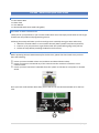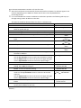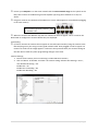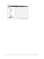
1
www.ness.com.au We know you are excited to get your hands on our AutoIP NVS (as you should be) but please read this quickstart guide before powering up. We know you are excited to get your hands on our AutoIP NVS (as you should be) but please read this quickstart guide before powering up. 1. Make sure your IP cameras are NOT connected to the customer’s computer network and NOT 1. Make sure your IP cameras are NOT connected to the customer’s computer network and NOT connected via a network switch. IP cameras must be connect directly into the Ness AutoIP NVS. connected via a network switch. IP cameras must be connect directly into the Ness AutoIP NVS. 2. Make sure to check out all our training videos on our YouTube channel (www.youtube.com/nesscorporation) as there might be features the NVS can do that you didn’t know about. 2. Make sure to check out all our training videos on our YouTube channel 3. Ensure you have read and understand the following pages. (www.youtube.com/nesscorporation) as there might be features the NVS can do that you didn’t know about. 3. Ensure you have read and understand the following pages. 1 | P a g e 104-460 Auto-IP NVS Premium Network Video Recorder QUICK START GUIDE 1 | P a g e 104‐460 ‐ AutoIP NVS Quick‐Start Guide INCLUDED IN THE BOX 1 x Ness AutoIP NVS 1 x Power lead 1 x User Manual 1 x AutoIP NVS Quick‐Start Guide (this guide) WELCOME TO NESS CORPORATION Thank you for your purchase! If you are new to Ness there are a few steps you will want to take to get familiar with the product and programming process. Following these steps will make your first install go more smoothly saving you time and money. 1. Watch the Tutorial Videos on our YouTube channel (www.youtube.com/nesscorporation) 2. Power it up at your premises to get familiar with the system before going to the job site, 3. Follow the steps below (Installing the NVS for the first time) INSTALLING THE NVS FOR THE FIRST TIME Before powering the Ness AutoIP NVS up for the first time, please check and make sure you have done the following: Ensure you have installed at least one hard drive and locked the drive bays. Ensure you have not connected any of the cameras into the customer’s network or into a network switch. Ensure you have connected a LAN cable from the ‘uplink’ on the NVS to a computer or network switch. Once you have confirmed the above then you are safe to turn the Ness AutoIP NVS on for the first time. 2 | P a g e Once the Ness AutoIP NVS is turned on for the first time: Allow the hard drives to automatically format and install on the NVS. This will take approx 5‐10 minutes depending on the HDD size. Please wait for this to be completed before proceeding further. It is recommended that a Static IP address be used where possible. The following will step you through setting a Static IP address in the NVS. The Static IP should be obtained from the client’s IT administrator. Action Display 1. Press the Enter button to access the OSD menu, “System Info” 2. Then press the “Down Arrow” to move to the next option, “System Set‐Up” which is ‘System Set‐Up’ 3. Press the “right arrow” to enter into System set‐up “Network Set‐up” 4. Press the ‘right arrow” to enter into Uplink Network settings “Ethernet 1” 5. Press the ‘Enter” button to change the ‘Connection Type’ “[1] Connection Type DHCP’ 6. Press the ‘Enter” button to enter the edit mode of ‘Connection [1] Connection Type Type’ DHCP 7. Then press the “Down Arrow”, to Select “Static” [1] Connection Type Static 8. Then press the “Enter button” to save the ‘Static Setting’ [1] Connection Type Static 9. The system will then Restart the Network [1] Connection Type Static 10. Then press the “Down Arrow” to move to the setting option of 000.000.000.000 the Static IP Address. 11. Press the ‘Enter” button to edit the Static IP Address 000. 000.000.000 Use the Up and Down arrows to select the IP Number required. Use the Right arrow to move to the next set of digits and again use the Up and down Arrows to select the required digits. 12. Once the full IP Address is set, Press the ‘Enter” button xxx.xxx.xxx.xxx 13. Then press the “Down Arrow”, to move to the Subnet mask [1] Netmask setting. Press Enter to change it, 255.255.255.000 14. Once you have set the Sub Netmask, then press the “Down [1] Gateway Arrow” to move to Gateway setting. 000.000.000.000 15. To set the Gateway, Press the ‘Enter” button to enter edit [1] Gateway mode Use the Up and Down arrows to select the IP Number 000. 000.000.000 required. Use the Right arrow to move to the next set of digits and again use the Up and down Arrows to select the required digits. 16. Once the full Gateway IP Address is set, Press the ‘Enter” [1] Gateway button xxx.xxx.xxx.xxx 17. Now press the ESC key four times to return to the normal screen (The IP address is now set) (For full details on Network Configuration please refer to section 3.3 on page 11 of the NVS Users Manual.) 3 | P a g e Ensure your computer is on the same network and the same network range as the ‘uplink’ on the NVS, then connect to the NVS using Internet Explorer (IE) using the IP address set in step 11 above. Plug your cameras into the back of the NVS one at a time. (Wait approx 5 seconds before plugging in the next camera.) Port one will represent Camera 1, Port 2= Camera 2 etc. When the cameras are added it may take 1‐5 minutes for them to appear. This is normal as the NVS needs to configure the cameras before they are displayed. Fault finding. (If after 5 minutes the cameras do not appear on the IE browser window, bring the camera to the NVS and plug into a port using a known good network cable. Once plugged in wait for approx 1‐5 minutes to confirm if the image appears. If it doesn’t then proceed check your camera settings in the NVS. Do not make any other programming changes at this time. Camera Settings; 1. Ensure the IP Camera you are connecting is a Ness NIP Series Camera, 2. Click on “Menu” of the NVS and check the camera setting ‘Advance PnP Setting’ is set to ; Use default PnP Setting = Yes Enable PnP = On Enable Port Forwarding = On Enable PoE Watchdog = On 4 | P a g e 3. Ensure ‘Activated’ is set to Yes. 5 | P a g e