1
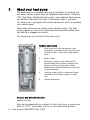
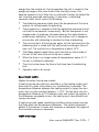
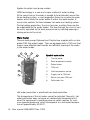
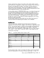
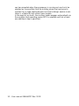
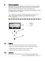
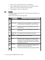
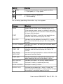
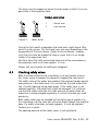
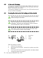
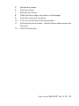
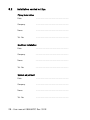
User manual
Atria
Atria Duo
Atria Duo Optimum
Atria Optimum
Comfort
Diplomat
Diplomat Duo
Diplomat Duo Optimum
Diplomat Duo Optimum G2
Diplomat Optimum
Diplomat Optimum G2
086U6297 Rev. 9 EN
Thermia Värme AB reserves the right to
make changes to components and specifi‐
cations without prior notice.
© 2010 Thermia Värme AB.
The Swedish language is used for the orig‐
inal instructions. Other languages are a
translation of the original instructions.
(Directive 2006/42/EC)
Contents
1
Foreword.................................................................................................... 3
2
Safety precautions....................................................................................... 4
2.1
Installation and maintenance......................................................................... 4
2.2
System modifications.................................................................................... 5
2.3
Safety valve................................................................................................. 5
3
About your heat pump................................................................................. 6
4
Control system.......................................................................................... 11
4.1
5
6
Keypad...................................................................................................... 11
4.2
Indicator.................................................................................................... 11
4.3
Display...................................................................................................... 12
4.4
Main Menu................................................................................................ 14
Settings and adjustments........................................................................... 15
5.1
Setting operating mode................................................................................ 15
5.2
Adjusting the indoor temperature.................................................................. 16
5.3
Reading off temperatures............................................................................. 19
5.4
Reading the operating time.......................................................................... 19
5.5
Manual defrost, outdoor unit........................................................................ 20
Regular checks......................................................................................... 21
6.1
Checking operation..................................................................................... 21
6.2
Check the water level in the heating circuit.................................................... 22
6.3
Check the brine circuit level......................................................................... 22
6.4
Checking safety valves................................................................................ 23
6.5
In the event of leakage................................................................................ 24
6.6
Cleaning the strainers for the heating and brine circuits................................... 24
7
Default setting in the control computer......................................................... 26
8
References............................................................................................... 27
8.1
Check list.................................................................................................. 27
8.2
Installation carried out by:........................................................................... 28
086U6297 Rev. 9 EN – 1
1
Foreword
Buying a heat pump from Thermia is an investment in a better future.
A Thermia heat pump is classed as a renewable energy source, which
means that it is considerate of our environment. It is a safe and con‐
venient solution that provides heating, hot water and in certain cases
cooling, for your home at a low cost.
We thank you for the confidence that you have shown in us by buying
a heat pump from Thermia. We hope that you will benefit from it for
many, many years to come.
With best wishes
Thermia Värme AB
User manual 086U6297 Rev. 9 EN – 3
2
Safety precautions
DANGER! The front of the heat pump must only be opened by
authorised service technicians.
Caution! This product is not intended for persons (including
children) with reduced physical, sensory or psychological
capacity, or who do not have knowledge or experience, unless
supervised or they have received instructions on how the
apparatus functions from a safety qualified person.
Note! Children are not permitted to play with the product.
The system can be considered maintenance free but certain checks
are necessary.
Before changing the control computer’s settings, first find out what
these changes mean.
Contact your installer for any service work.
2.1
Installation and maintenance
DANGER! Only authorized installers may install, operate and
carry out maintenance and repair work on the heat pump.
DANGER! Only authorized electricians may modify the
electrical installation.
4 – User manual 086U6297 Rev. 9 EN
DANGER! Only authorized refrigeration technicians may work
on the refrigerant circuit.
2.2
System modifications
Only authorized installers may carry out modifications on the following
components:
•
•
•
The heat pump unit
The pipes for the refrigerant, brine, water and power
The safety valve
Do not carry out construction installations that may affect the opera‐
tional safety of the heat pump.
2.3
Safety valve
The following safety precautions apply to the hot water circuit’s safety
valve with corresponding overflow pipe:
•
•
Never block the connection to the safety valve’s overflow pipe.
Water expands when it is heated, this means that a small amount
of water is released from the system via the overflow pipe. The
water that exits the overflow pipe can be hot! Therefore, allow it to
flow to a floor drain where there is no risk of burning yourself.
User manual 086U6297 Rev. 9 EN – 5
3
About your heat pump
The heat pump is a complete heat pump installation for heating and
hot water. Certain models have an integrated water heater. Using the
TWS (Tap Water Stratificator) technology, more effective heat transfer
and efficient layering of the water in the water heater is achieved.
The heat pump is equipped with control equipment, which is operated
via a control panel.
Heat enters the house via a water borne heating system. The heat
pump supplies as much of the heat demand as possible before auxili‐
ary heating is engaged and assists.
The heat pump unit consists of five basic units:
Symbol explanation
3
1
Heat pump unit with compressor, heat
exchanger, circulation pumps for brine and
heating systems, valves and safety equip‐
ment.
2
Water heater
3
Exchange valve or shunt valve that the
heated water either passes through to the
heating system or to the water heater
depending on whether heating or hot water
is to be produced
4
Auxiliary heater with an immersion heater
installed on the heating system’s supply
line.
5
Control equipment
5
2
4
1
Outdoor and defroster function
Applies to Atria.
Atria are equipped with an outdoor unit that uses air as a heat source
down to -20°C. The outdoor unit has a coil where brine recovers
6 – User manual 086U6297 Rev. 9 EN
energy from the outside air. During operation the coil is cooled by the
energy exchange at the same time as the humidity causes it to
become covered in frost. Atria has an automatic function to defrost the
coil using the produced heat energy. If necessary, a defrosting
sequence starts which means the following:
•
•
•
•
•
•
•
The defrosting sequence starts when the temperature of the brine
reaches its set parameter for defrosting.
The compressor is stopped so that the defrosting sequence should
not load the compressor unnecessarily. But the compressor is not
stopped when it produces hot water because the water heater is
cooled when defrosting. The fan on the outdoor unit is stopped in
conjunction with defrosting to shorten the time of defrosting.
The shunt valve in the heat pump opens so that hot brine from the
defrosting tank is mixed with the cold brine circulating to the out‐
door unit. The mixture has a temperature of about 15°C.
The fifteen degree heated brine melts the frost on the outside of
the coil at the same time as the liquid is cooled.
When the brine is no longer cooled to temperatures below 11°C
the coil is sufficiently defrosted.
The shunt valve closes the flow of hot brine from the defrosting
tank.
Operation returns to normal.
Speed (rpm) control
Applies to certain heat pump models.
A heat pump requires optimum conditions in the heating system and
brine circuit in order to be able to run as efficiently as possible. The
temperature difference between the heating system’s supply line and
return line must be constant between 7–10°C. For the brine circuit a
temperature difference of 3°C between input and output line applies. If
the differences are greater or less, the heat pump is less efficient and
savings are lower.
A heat pump with speed controlled circulation pumps always ensures
that they retain the temperature differences. The control equipment
detects if the balance is upset and increases or decreases the speed of
the circulation pumps as necessary.
HGW technology
User manual 086U6297 Rev. 9 EN – 7
Applies to certain heat pump models.
HGW technology is a new and unique method of water heating.
At the same time as the water is heated to be distributed around the
house heating system, a small proportion flows via an extra de-super‐
heater, which heats the water before it enters the water heater. A
shunt valve controls the flow between hot water and heating system.
During heating production, the shunt ensures a certain flow over the
de-superheater to the water heater. The flow through the shunt is con‐
tinuously regulated by the heat pump control by sending opening or
closing pulses to the shunt.
Water heater
Thermia heat pumps Diplomat and Comfort are supplied with an inte‐
grated 180 litre water heater. They are equipped with a TWS coil that
means more effective heat transfer and efficient layering of the water
in the water heater.
2
7
1
8
6
3
Symbol explanation
1
Tap hot water
2
Peak temperature sensor
3
Water heater
4
TWS coil
4
5
Start temperature sensor
5
6
Supply line to TWS coil
7
Return line from TWS coil
8
Cold water line
Hot water production is prioritised over heat production.
The temperature of the hot water cannot be adjusted. Normally, hot
water production does not cease at a determined temperature but
when the compressor’s operating pressure switch reaches its maxi‐
mum operating pressure, which corresponds to a hot water tempera‐
ture of approximately 50-55°C.
8 – User manual 086U6297 Rev. 9 EN
Using a regular time interval, the water in the water heater is given
extra heat by the integrated auxiliary heater to prevent the build up of
bacteria (anti-legionella function). The factory set time interval is
seven days (can be adjusted). When the anti-legionella function is
active the heat pump produces hot water until the temperature for the
start temperature sensor (5) has reached 60°C.
In the control system’s TEMPERATURE menu, a number of measured
and calculated temperatures for the hot water and supply are dis‐
played. The current temperature for the peak temperature sensor (2)
and the temperature of the supply line during heating and hot water
production are displayed. The temperature of the supply line often
exceeds the maximum permitted hot water temperature, but usually
during hot water production.
The hot water heaters for Atria differ from the other heat pumps in
that the function for defrosting the outdoor unit is different.
Auxiliary heat
If the heat demand is greater than the heat pump’s compressor
capacity, the auxiliary heater engages automatically in operating mode
AUTO. The auxiliary heater is made up of an electric heating element
on the supply line that has two outputs, AUX. HEAT 1 and AUX.
HEAT 2, and can be controlled in three steps. Atria has three outputs,
AUX. HEAT 1, AUX. HEAT 2 and AUX. HEAT 3 and output can be
controlled in five steps.
Table 1.
auxiliary heater output steps in kW
Diplomat, Duo, Comfort
Atria
230V
400V
230V
400V
Step 1
1,5
3
1,5
3
Step 2
3
6
3
6
Step 3
4,5
9
4,5
9
Step 4
12
Step 5
15
Step +4
12
Step +5
15
The two power steps, step 4 and step 5 for Atria cannot be activated
when the compressor is running. Auxiliary heater step: +4 and +5
User manual 086U6297 Rev. 9 EN – 9
can be connected when the compressor is running and must only be
selected on the condition that the building where the heat pump is
installed has a large heating demand and the building’s electric instal‐
lation is suitable for high current consumption.
In the event of an alarm, the auxiliary heater engages automatically on
the condition that operating mode AUTO is selected and that at least
one additional step is permitted.
10 – User manual 086U6297 Rev. 9 EN
4
Control system
The heat pump has an integrated control system which automatically
calculates the heat demand in the house to ensure that the correct
amount of heat is produced and emitted where necessary.
The control panel is operated using a keypad and information is shown
in a display and by an indicator.
Note! The information in the display and menus will vary
depending on the heat pump model and connected
accessories.
ROOM
20°C
NO HEAT DEMAND
3
OPERAT. AUTO
1.
2.
3.
Keypad
Indicator
Display
1
2
4.1
Keypad
+ Plus sign used to scroll up a menu and increase the values.
- Minus sign used to scroll down a menu and reduce the values.
> Right arrow used to select a value or open a menu.
< Left arrow to cancel selection or exit a menu.
4.2
Indicator
The indicator at the bottom of the control panel has three modes:
User manual 086U6297 Rev. 9 EN – 11
•
•
•
4.3
Not lit, means that the heat pump is not powered.
When the green light shines continuously, the heat pump has
power and is ready to produce heat or hot water.
Flashing green, means an active alarm.
Display
The display shows information about the heat pump’s operation, sta‐
tus and any alarms.
Symbols that show the heat pump status:
Symbol
HP
Meaning
Indicates that the compressor is in operation.
LIGHTNING Indicates that the auxiliary heater is in operation. The
number indicates what additional step is activated.
F
HOUSE
Indicates that the heat pump produces heat for the
heating system.
TAP
Indicates that the heat pump produces heat for the
water heater.
FLOW SEN‐ An F indicates that a flow sensor is installed.
SOR
CLOCK
Indicates that tariff control is active.
TANK
Indicates the level of hot water in the water heater.
When hot water is produced for the water heater, this is
indicated by a flashing icon for the tank. A lightning
symbol by the symbol indicates peak heating charging
(anti-legionella function).
SQUARE
Either indicates that the operating pressure switch has
deployed, or that the pressure pipe temperature has
reached its maximum temperature.
DEFROST
Displayed when defrosting is active (applies to Atria).
12 – User manual 086U6297 Rev. 9 EN
Symbol
Meaning
FAN
Displayed when the fan is active (applies to Atria).
L = Low speed, H = High speed
COOLING
Displayed if cooling is produced.
A = Active cooling.
The following operating information may also appear:
Message
Meaning
ROOM
Shows the set ROOM value. Standard value: 20°C.
If the accessory room sensor is installed it shows the
actual temperature and the desired indoor temperature
is shown within brackets.
START
Indicates that there is a need for heat production or
hot water and that the heat pump will start.
EVU STOP
Indicates that the additional function EVU is active.
This means that the heat pump is off as long as EVU
is active.
NO HEAT DEMAND Indicates that there is no heating or hot water produc‐
tion demand.
HEAT PUMP
START --XX
Indicates that there is a need for heat production or
hot water and that the heat pump will start in XX
minutes.
HEAT PUMP
+ADD.HEAT
Indicates that heat production is active with both com‐
pressor and auxiliary heater.
START_MIN
Indicates that there is a demand for heating or hot
water production but that a start delay is active.
ADD. HEATER
Indicates that there is an auxiliary heater demand.
COOLING
Displayed if cooling is produced passively.
ACTIVE COOLING
Displayed if cooling is active.
DEFROST X(Y)
Displayed when defrosting is active. X shows the
actual reached temperature. Y shows at which temper‐
ature defrost is complete (applies to Atria).
User manual 086U6297 Rev. 9 EN – 13
4.4
Main Menu
The display's INFORMATION menu is used to set and adjust the heat
pump functions and is opened by pressing the left or right buttons.
The menu has the following appearance:
2
3
4
INFORMATION
OPERAT.
HEAT CURVE
TEMPERATURE
OPERAT. TIME
DEFROST
1
1.
2.
3.
4.
Sub-menus
Return
Cursor
If an arrow is shown, it indi‐
cates that more sub menus
are continued underneath
Press the + and - buttons to move the cursor between the sub-menus.
Press the right button to select a sub-menu. Press the left button to go
back in the menu.
14 – User manual 086U6297 Rev. 9 EN
5
Settings and adjustments
An authorized installer carries out the basic settings of the heat pump
at installation. A number of settings and adjustments that you can
carry out yourself are described below.
Note! Before changing the control computer’s settings, first
find out what these changes mean. Make a note of the default
setting.
5.1
Setting operating mode
1.
OPERAT.
AUTO
HEAT PUMP
AUX. HEATER
HOT WATER
2.
3.
4.
Open the menu OPERAT. in the
INSTALLATION menu. The asterisk
shows the current selection
Mark new mode using + or – button.
Press the right button once to confirm
the choice.
Press the left button twice.
The following operating modes can be selected:
Operating mode
(OFF)
Meaning
The installation is fully switched off. This mode is also
used to acknowledge certain alarms.
AUTO
The heat pump and the auxiliary heater are automati‐
cally controlled by the control system.
HEAT PUMP
The control system is controlled so that only the heat
pump unit (compressor) is allowed to operate. In this
operating mode peak heating charging (anti-legionella
function) of the hot water will not run because the auxil‐
iary heater is not used.
User manual 086U6297 Rev. 9 EN – 15
Operating mode
Meaning
ADD. HEATER
The control system only permits the auxiliary heater to
be in operation.
HOT WATER
In this mode the heat pump only produces hot water, no
heat goes to the heating system.
Caution! If the operating mode OFF or HOT WATER is to be
used for long periods during the winter, the water in the
heating system in the heating system must be drained,
otherwise there is a risk of frost damage.
5.2
Adjusting the indoor temperature
The indoor temperature is adjusted by changing the heat pump’s heat
curve, which is the control system’s tool for calculating what the sup‐
ply temperature should be for water that is sent out in the heating sys‐
tem. The heat curve is a graph that compares the outdoor temperature
with the supply temperature. The colder the outdoor temperature the
more heat is supplied to the heating system. The heat curve will be
adjusted in connection with installation. It must be adapted later on,
however, to obtain a pleasant indoor temperature in any weather con‐
ditions. A correctly set heat curve reduces maintenance and saves
energy.
There are two ways of adjusting the heat curve, partly in the HEAT
CURVE sub-menu, partly with the ROOM value.
Adjusting the HEAT CURVE
A typical heat curve is shown below. At an outdoor temperature of 0°C
the supply temperature should be 40°C. At outdoor temperatures
colder than 0°C, supply water hotter than 40°C is sent out to the radi‐
ators and at outdoor temperatures greater than 0°C, supply water
cooler than 40°C is sent out. When you increase the CURVE value,
the heat curve will become steeper and when you reduce it, it will
become flatter.
16 – User manual 086U6297 Rev. 9 EN
This is the most energy and cost efficient way to set the indoor tem‐
perature and should therefore be used for long term temperature set‐
tings.
1
56
2
5
40
24
1.
2.
3.
4.
5.
Supply temperature (°C)
Maximum setpoint value°
Outdoor temperature (°C)
0°C
°Set value (standard 40°C)
3
20
0
-2 0
4
The following parameters can be adjusted:
Parameter
Description
CURVE
If the CURVE value is increased, the heat curve will become
steeper and if the value is reduced, it will become flatter.
Raise for hotter indoor temperature, reduce for lower temper‐
ature.
MIN
Lowest set point for supply temperature.
MAX
Highest set point for supply temperature.
CURVE 5
Used to adjust the heat curve at an outdoor temperature of
+5°C.
CURVE 0
Used to adjust the heat curve at an outdoor temperature of
0°C.
User manual 086U6297 Rev. 9 EN – 17
Parameter
Description
CURVE -5
Used to adjust the heat curve at an outdoor temperature of
-5°C
HEAT STOP
This function stops all production of heat when the outdoor
temperature is equal to, or higher than, the set heat stop
value.
Note! High temperatures in an underfloor heating system can
damage parquet floors.
Adjust the heat curve in the HEAT CURVE menu as follows:
HEAT CURVE
CURVE
MIN
MAX
CURVE 5
CURVE 0
CURVE -5
HEAT STOP
40˚C
22˚C
70˚C
0˚C
0˚C
0˚C
17˚C
1.
2.
3.
4.
5.
Open the menu HEAT CURVE. in the
INSTALLATION menu.
Mark desired parameter using + or – but‐
ton.
Open the parameter by pressing the right
button once.
Raise or reduce the value with the + or button.
Press the left button three times.
Adjusting ROOM values
The heat curve and therefore the indoor temperature can be affected
by changing the "ROOM" value. If the ROOM value is used to affect
the system’s heat curve, the heat curve does not become steeper or
flatter, which the curve becomes if the CURVE value changes, instead
the entire heat curve is moved by 3°C for every degree change of the
ROOM value.
Note! For a temporary increase or reduction of the indoor
temperature, adjust the ROOM value instead.
Change the ROOM value as follows:
18 – User manual 086U6297 Rev. 9 EN
1.
2.
3.
5.3
Press either the + or - button once to open and change the
ROOM value.
Raise or reduce the ROOM value using the + or - buttons to
change the indoor temperature.
Wait ten seconds or press the left button once to exit the menu.
Reading off temperatures
TEMPERATURE
OUTDOOR
ROOM
SUPPLY LINE
RETURN LINE
HOT WATER
INTEGRAL
BRINE OUT
0˚C
20˚C
38(70)˚C
34(48)˚C
52˚C
-660
-7˚C
The set point value for the supply line and the
max value of the return line is shown within
brackets The max value indicates the tempera‐
ture at which the compressor is stopped. No val‐
ues can be changed in this menu.
The different temperatures that the installation has are shown here. All
temperatures are stored for 100 minutes back in time so that they can
also be displayed in the form of graphs.
If ROOM shows 20°C the heat curve is unaffected. If ROOM shows
higher or lower, this indicates that the heat curve has been adjusted
up or down.
5.4
Reading the operating time
OPERAT. TIME
HEAT PUMP
AUX. HEAT 1
AUX. HEAT 2
HOT WATER
0H
0H
0H
0H
HEAT PUMP shows the total time in hours that the heat pump has
been in operation since installation.
AUX. HEAT 1 and 2 refer to the auxiliary heater power stage 3 kW
and 6 kW.
HOT WATER is included in the total time HEAT PUMP and indicates
the number of hours that hot water production has been in operation
since installation.
User manual 086U6297 Rev. 9 EN – 19
5.5
Manual defrost, outdoor unit
If the heat pump requires defrosting you can run a defrosting proce‐
dure manually from the control computer.
To defrost manually:
1.
Press either the right or left button once to open the INFORMA‐
TION menu. The cursor is in the OPERATION menu option.
2.
Press the down button to move the cursor to the DEFROST
menu option.
3.
Open the menu by pressing the right button once.
4.
Press the down button to move the cursor to the MANUAL
DEFROST menu option.
5.
Press the right button once.
6.
Press the up button once to start defrost.
7.
Press the left button three times to exit the menu.
20 – User manual 086U6297 Rev. 9 EN
6
Regular checks
6.1
Checking operation
During normal operation, the alarm indicator lights green continuously
to show
that everything is OK. When the alarm is triggered, it flashes green at
the same time as a text message is shown in the display.
ALARM
LOW PRESSURE ERROR
Regularly check the alarm indicator
to ensure that the installation is
working correctly. In event of alarm
the heat pump will if possible supply
heating to the house, primarily with
the compressor, secondarily with the
auxiliary heater. Hot water will stop
to indicate that something notewor‐
thy has occurred.
In event of alarm this is indicated in the display with the text ALARM
and an alarm message. The potential alarm messages are:
Message
Meaning
HIGH PRESSURE The heating circuit is the heat pump's high pressure cir‐
ERROR
cuit.
Check, and, if necessary, rectify the circuit level as
below. Reset the alarm as follows
LOW PRESSURE
ERROR
The brine circuit is the heat pump's low pressure circuit.
Check the circuit level as below. Contact the service
technician.
User manual 086U6297 Rev. 9 EN – 21
Message
Meaning
ERR PHASE SEQ. Can be displayed in conjunction with interference in the
mains network, for example after a temporary power cut.
Reset the alarm as follows. If necessary switch off the
power supply for a minute or two.
Other alarm mes‐
sage
Reset the alarm as follows. If the alarm remains contact
a service technician.
Resetting the alarm
For alarms that are not reset automatically acknowledgement is
required. Acknowledge the alarm by setting the heat pump to operat‐
ing mode OFF and then back to the desired operating mode.
6.2
Check the water level in the heating circuit
The line pressure of the installation must be checked once a month.
The external manometer must show a value between 1-1.5 bar. If the
value is below 0.8 bar, when the water in the heating system is cold,
the water must be topped up (applies in the event of an empty expan‐
sion tank). You can use normal tap water when topping up the heating
system. In certain exceptional cases the water quality may be so poor
(for example very hard water) that it is not suitable for filling the heat‐
ing system. If unsure, contact your installer.
Note! Do not use any additives for water treatment in the
heating system’s water!
Note! The closed expansion tank contains an air filled bladder
that absorbs variations in the heating system’s volume. Under
no circumstances may it be drained of air.
6.3
Check the brine circuit level
The brine circuit must be filled with the correct amount of fluid other‐
wise operational interruptions may occur.
22 – User manual 086U6297 Rev. 9 EN
The brine must be topped up when the level drops so that it is no lon‐
ger visible in the expansion tank.
Symbol explanation
1
Figure 1.
2
1
Correct level
2
Level too low
Level, brine
During the first month of operation the brine level might drop a little,
which is quite normal. The fluid level may also vary depending on the
temperature of the heat source. Under no circumstances, however,
must the fluid level be allowed to drop so much that it is no longer
visible in the expansion tank.
For Atria, Atria Duo with pressurized brine circuit the manometer on
the expansion tank must show approx. 1.0 bar.
Always call your installer for refilling of refrigerant.
6.4
Checking safety valves
Both the safety valves for the installation must be checked at least
four times a year to prevent lime deposits clogging the mechanism.
The safety valve of the water tank protects the enclosed heater against
over pressure in the water tank. It is mounted on the cold water inlet
line, its outlet opening facing downwards. If the safety valve is not
checked regularly, the water tank might be damaged. It is quite nor‐
mal that the safety valve lets out small amounts of water when the
water tank is being charged, especially if a lot of hot water was used
previously.
Both safety valves can be checked by turning the cap a quarter of a
turn clockwise until the valve lets out some water through the overflow
pipe. If a safety valve does not work properly, it must be replaced.
Contact your installer.
The opening pressure of the safety valves is not adjustable.
User manual 086U6297 Rev. 9 EN – 23
6.5
In the event of leakage
In the event of leakage in the hot water pipes between the heat pump
and water taps, close the shut-off valve on the cold water inlet imme‐
diately. Then contact your installer.
In the event of leakage in the brine circuit, turn off the heat pump and
call your installer immediately.
6.6
Cleaning the strainers for the heating and brine circuits
Note! The heat pump must be switched off at the main switch
before cleaning can be started.
Note! The strainers must be cleaned twice a year after
installation. The interval can be extended if there is evidence
that cleaning twice a year is not necessary.
Note! Have a cloth to hand when opening the strainer cover
as a small amount of water usually escapes.
1
3
4
2
2
4
1
3
1
1.
2.
3.
4.
Shut off tap
Cover
Strainer
O-ring
Clean the strainers as follows:
1.
Switch off the heat pump.
2.
For the brine circuit strainer - remove the insulation around the
filler cock.
3.
Turn the shut-off cocks to the closed position (see figure above).
4.
Unscrew the cover and remove it.
24 – User manual 086U6297 Rev. 9 EN
5.
6.
7.
8.
9.
10.
11.
12.
Remove the strainer.
Rinse the strainer.
Reinstall the strainer.
Check that the o-ring on the cover is not damaged.
Screw the cover back into place.
Turn the shut-off cock to the open position.
For the brine circuit strainer - reinstall the insulation around the
filler cock.
Start the heat pump.
User manual 086U6297 Rev. 9 EN – 25
7
Default setting in the control computer
The first column in the table below shows the parameters that can be
adjusted by the User. The second column shows settings made at the
factory, and the third column the settings made by the installation
contractor in connection with installation of the heat pump.
Setting
Factory setting
ROOM
20°C
OPERAT.
AUTO
CURVE
40°C
MIN
10°C
MAX
55°C
CURVE 5
0°C
CURVE 0
0°C
CURVE -5
0°C
HEAT STOP
17°C
26 – User manual 086U6297 Rev. 9 EN
Any customer specific
settings
8
References
8.1
Check list
Installed model: ..................................................................
•
•
•
•
•
•
•
Setting up
o
Surface adjustment
Piping installation
o
Leak test
o
Bleeding
o
Open radiator valves
o
Function test safety valve
Electrical Installation
o
Direction of rotation of the compressor
o
Outdoor sensor
o
Accesso‐
ries: .......................................................................
Brine installation
o
Type of brine: ........................................................
o
Filling, number of
litres: ......................................................
o
Leak test
o
Function test safety valve
Control computer
o
Basic settings
Test operation
o
Manual test carried out
o
Noise check
Customer information
o
Control computer, menus, User manual
o
Checking and filling, heating system
o
Alarm information
o
Function test safety valve
o
Strainers, cleaning
o
Trimming information
o
Warranties
User manual 086U6297 Rev. 9 EN – 27
8.2
Installation carried out by:
Piping installation
Date
........................................................
Company
........................................................
Name
........................................................
Tel. No.
........................................................
Electrical Installation
Date
........................................................
Company
........................................................
Name
........................................................
Tel. No.
........................................................
System adjustment
Date
........................................................
Company
........................................................
Name
........................................................
Tel. No.
........................................................
28 – User manual 086U6297 Rev. 9 EN
086U6297 Rev. 9 EN