1
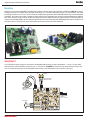
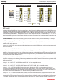
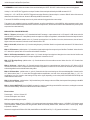
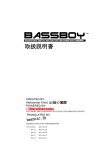
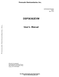
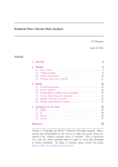
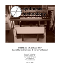
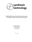
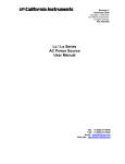
tm
BassBoy
Manual
MIDI Device
Monophonic digital MIDI controlled bass synthesizer
CREATED BY:
Aleksandar Krstić @
POWERED BY:
BassBoy
technical support : [email protected]
BassBoy
BassBoy is a monophonic digital MIDI controlled bass synthesizer. Device receives all information via MIDI input (MIDI IN connector).
Sampling frequency is 31.25KHz which generates audio range up to 15.625Khz. Although it's based on 8-bit processor, the signal
processing inside the unit is 16-bit. The unit consists of oscillator which generates SAW & SQUARE WAVE using 16-bit band-limited
wavetables, thus making the number of harmonics limited. After that, the signal itself goes through a simple implementation of MOOG
filter, whose frequency range is chosen by MIDI commands and which is affected by the level of the envelope. The filtered signal then
comes to the controlled amplifier, which creates the signal shape, and in the end through DAC (WM8762) and pre-amp circuit goes to the
audio jack 6.35mm. The unit is mono, and 6.35mm jack is also used as carrier for the circuit board itself.
Figure 1-1: BassBoy
IMPORTANT!!!
It is crucial that the power supply unit connected to the BassBoy (PS connector) is within specifications : +10V to +13V max. MIDI
channel and the note interpretation mode (from now on, refered to as CH&MODE connector) must be chosen before turning on the
unit. The location of the jumpers for choosing MIDI channel and the note interpretation mode is shown on the fig1-3.
POWER
ON
C
MIDI
RECEIVE
A
A
C
Low Current LEDS or
LEDS with mcd>200
4
5
MIDI INPUT
DIN5 Female Connector
Front View
+
POWER SUPPLY
INPUT, DC
+10V ... +13V max
Audio Output
Figure 1-2: Wiring diagram
MikroElektronika
BassBoy
technical support : [email protected]
SEQ MODE with CHANNEL SELECTION
LIVE MODE with CHANNEL SELECTION
MIDI CH1
MIDI CH9
MIDI CH1
MIDI CH9
MIDI CH2
MIDI CH3
MIDI CH10
MIDI CH2
MIDI CH10
MIDI CH11
MIDI CH3
MIDI CH11
MIDI CH4
MIDI CH12
MIDI CH4
MIDI CH12
MIDI CH5
MIDI CH13
MIDI CH5
MIDI CH13
MIDI CH6
MIDI CH14
MIDI CH6
MIDI CH14
MIDI CH7
MIDI CH15
MIDI CH7
MIDI CH15
MIDI CH8
MIDI CH16
MIDI CH8
MIDI CH16
LEGEND:
JUMPER
FREE
Figure 1-3: CHANNEL & MODE JUMPER POSITION
MIDI control
Selection of SAW or SQUARE wave is done via Program Change, where Program 1 is SAW wave and Program 2 is SQUARE wave, then
sequentially repeats SAW wave as Program 3, SQUARE wave as Program 4 and so on until Program 128. The unit has two ways of
interpretation of received MIDI notes: SEQUENCER MODE and LIVE MODE. Interepretation mode is selected via jumper located on
connector labeled as “CH&MODE”, while reproduced notes are within range from MIDI note 24 to MIDI note 72 (C1 – C5). The unit
doesn't support MIDI pitch change control. Duration and level of envelope only affects the filter. In case that note has accent, then it also
affects the controlled amplifier.
SEQUENCER MODE is mode in which the way of playing current note depends on the way the last note was played. The way of
playing the note is defined by it's velocity, which is shown in this table:
Velocity 0 = NOTE OFF . It has the same meaning as a standard MIDI message $80 note $00. This defines end of duration of
audibility (GATE) of the same note.
Velocity 1 - 16 = NOTE OFF. Note is being turned off, unless the previous note had a SLIDE function, in which case it lasts as long as the
GATE of the same note.
Velocity 17 - 32 = NOTE OFF + SLIDE. Similar to the previous case, but this time note stays on until the next note.
Velocity 33 - 48 = NOTE ON. Duration of the note is defined by the GATE. It turns the note on and triggers the envelope, but it is
applied only if the previous note doesn't have SLIDE turned on ( portamento, gradual slide from previous note to current note). If the
previous note had SLIDE turned on, then envelope wouldn't be triggered and only SLIDE effect would be executed. Duration of the
envelope is defined by MIDI command CC 57.
Velocity 49 - 64 = NOTE ON + SLIDE. Duration of the note is until next note and is not defined by GATE. It turns the note on and
triggers the envelope, but it is applied only if the previous note doesn't have the SLIDE turned on. If the previous note had the SLIDE
turned on, then envelope wouldn't be triggered and only the SLIDE effect would be executed. Duration of the envelope is defined by
MIDI command CC 57.
Velocity 65 - 80 = NOTE OFF + ACCENT. Same as NOTE OFF. Left for compatibility reasons.
Velocity 81 - 96 = NOTE OFF + ACCENT + SLIDE. Same as NOTE OFF + SLIDE. Left for compatibility reasons.
Velocity 97 – 112 = NOTE ON + ACCENT. Duration of the note is defined by the GATE. It turns the note on and triggers the
envelope, but it is applied only if the previous note doesn't have SLIDE turned on. If the previous note had SLIDE turned on, then
envelope wouldn't be triggered and only SLIDE effect would be executed. Duration of an envelope is a constant ~250mS. Value of
the accent is added to the level value of the note. Accent is defined by the MIDI command CC 58.
Velocity 113 - 127 = NOTE ON + ACCENT +SLIDE. Duration of the note is until next note and is not defined by the GATE. It turns
the note on and triggers the envelope, but it is applied only if the previous note doesn't have the SLIDE turned on. If the previous
note had SLIDE turned on, then envelope wouldn't be triggered and only SLIDE effect would be executed.Duration of the envelope
is a constant ~250mS. Value of the accent is added to the level value of the note. Accent is defined by the MIDI command CC 58.
MikroElektronika
technical support : [email protected]
BassBoy
LIVE MODE is a mode in which the duration of the note is defined by the GATE. VELOCITY defines the way notes are being played:
Velocity 0 – 100 = NOTE ON. Triggers the envelope. Duration of the envelope is defined by the MIDI command CC 57.
Velocity 101 – 127 = NOTE ON + ACCENT.Triggers the envelope. Duration of the envelope is constant ~250mS. Value of the accent is
added to the level value of the note. Accent is defined by the MIDI command CC 58.
Function AUTO-SLIDE is constantly turned on only in this mode and is triggered when notes overlap.
This mode is more suitable for playing over MIDI keyboard, as well as controlling the unit via MIDI file, while sequencer mode is more
suitable for work with older sequencers that don't have note overlap function, but can also be used for work with MIDI files (easier input of
sequences from other bass lines).
MIDI CONTROL CHANGE MESSAGES
Midi CC 7 Volume. (default value = 127). A standard defined CC message – output volume level. In 127 steps of 0.5dB, where value 0 is
value for MUTE, and value 127 = 0db (relative) maximum output level. Steps are logarithmic, and transition between the steps is linear for
a smooth transition.
Midi CC 53 Filter Pre-Gain. (default value = 0). Controls input signal level into the filter. Low value, hard resonance, but soft sound.
Higher value, lower resonance, but harder sound. Values from 0 to 127.
Midi CC 54 Cut-Off. (default value = 0). Controls cutting frequency of the filter. Works in conjunction with command CC 56. Values from 0
to 127.
Midi CC 55 Resonance. (default value = 0). Controls the signal level brought from output to input of the filter. Feedback. Values from 0 to
127. Value 112 is optimal, while 127 is near the self oscillation of the filter.
Midi CC 56 Envelope modulation. (default value = 0). Controls the signal envelope level brought to the control level of the filter and
affects the cutting frequency of the filter. Envelope is logarithmic. Values from 0 to 127.
Midi CC 57 Envelope Decay. (default value = 0). Controls duration of the note without accent. Values from 0 to 127. Duration from
~250mS to ~2s.
Midi CC 58 Accent. (default value = 0). Controls intensity of the accent on notes with accent. Values from 0 to 127. When in CC 55
resonance is minimum value, envelope which comes to filter is logarithmic, but when CC 55 resonance is at maximum value, envelope is
softened logarithmic and sounds like a little ducky effect.
Midi CC 59 Distort Gain. (default value = 4, gain x2). Controls level of the sound coming out of the controlled amplifier. Values from 0 to
127. Where values from 0 – 3 mean direct throughput without amplification, and rest of the values are MIDI Value 4 – 127 / 2 =
amplification 2x to 63x. It leads to hard cutting off of top of the signal, depending on the value (HARD CLIPPING DISTORTION) and
makes distortion of the sound.
Midi CC 60 Cut-Off step. (default value = 30) Controls fluency of the change to the cut-off filter, that is speed of step change to the MIDI
command CC 54. Values 0 to 127.
Midi CC 123 ALL NOTES OFF. Used as PANIC command. In case the note didn't get turned off for some reason, sending this command
note is turned off instantly. Value doesn't affect execution of the command.
Electrical data:
Power supply : +10V to +13V max, DC
Current consumption: max. 100mA
MIDI input separated by opto-coupler.
Maximum output voltage: approx. 2.2VRMS = 6.2V peak-to-peak output impedance 1MOhm, approx. 1.95VRMS = 5.5V peak-to-peak
output impedance 10kOhm (measured with generated SINE wave directly towards DAC, measured on the 6.35mm jack). Output
impedance > 10KOhm.
Notes are in range from 32.70Hz to 523.25Hz, that is MIDI note 24 to MIDI note 72 (C1 – C5) (maximum deviation +/-1.5 cents).
MikroElektronika
BassBoy
technical support : [email protected]
D2
+VCC
D2 ... D7 = 1N4007
+3.3V
D7
3
1
1
2
C2
C11
C12
100nF
330u
100nF
C13
C14
100nF
330u
TLV1117-3.3
GND
GND
GND
GND
GND
GND
C7
100nF
GND
GND
+3.3V
1
6
2
5
1N4148
3
4
32.000MHz
MIDI RX
R15
100K
MIDI CHANNEL & MODE
SELECT
CN1
+3.3V
9
7
5
3
1
OSC1
1
GND
+3.3V
27
26
25
24
23
22
21
20
CLOCK
CNY17-3
NC
4
+V
GND
GND
10
8
6
4
2
2
MIDI DATA
+3.3V
2
8.000MHz
OPTIONAL EXTERNAL CLOCK
LEDS
GND
PR0/XTAL2
PR1/XTAL1
U1
8.000MHz
CR1
15pF
C16
GND
1
C1
100nF
R1
10K
CN2
GND
3
2
1
35
34
RESET/PDI_CLK
PDI_DATA
3
2
1
44
43
42
41
40
ADC7/PA7
ADC6/PA6
ADC5/PA5
ADC4/PA4
ADC3/PA3
ADC2/PA2
ADC1/PA1
ADC0/PA0
PE3
PE2
PE1/SCL(TWIE)
PE0/SDA(TWIE)
36
37
3
GND OUT
C8
100nF
PD7/CLKOUT/SCK(SPID)
PD6/MISO(SPID)
PD5/MOSI(SPID)
PD4/SS(SPID)
PD3/TXD1
PD2/RXD1
PD1/XCK1
PD0
33
32
29
28
CN5
1
2
3
+3.3V
PB3/ADC11
PB2/ADC10
PB1/ADC9
PB0/ADC8
OUT
R4
10K
D1
MIDI IN
1K
OPTO1
220
1
2
7
6
5
4
R2
MIDI DATA
R3
CN3
+3.3V
2
4
IN
OUT
GND OUT
PS
DC POWER
SUPPLY
+3.3V
U4
9
19
31
39
D6
VCC
VCC
VCC
AVCC
D5
GND
GND
GND
GND
D4
PDI_PGM
GND
17
16
15
14
13
12
11
10
(SPI)SCK/PC7
(SPI)MISO/PC6
(SPI)MOSI/PC5
(SPI)SS/PC4
TXD0/PC3
RXD0/PC2
(TWIC)SCL/XCK0/PC1
(TWIC)SDA/PC0
DAC CLK
DAC DATA
MIDI RX
DAC WS
ATXMEGA32D4
8
18
30
38
D3
CN4
15pF
C15
R9
1K5
GND
Gnd
GND
+VCC
GND
R11
100
C10
100nF
R8
100K
R7
1K
+3.3V
+3.3V
R10
Q1
BC550C
or
2SC2240
3K3
C3
+3.3V
VDD
C4
10uF
tant 16V
100nF
GND
CLOCK
32.000MHz
11
D
PR
DAC CLK
DAC WS
U2B
Q
9
+3.3V
CLR Q
7
U3
VOUTR
VOUTL
8
5
R5
R6
3K3
10K
R14
tant 16V
10uF
C9
AUDIO OUTPUT
WT
TN
RN
WR
WS
SN
1K
R12
10K
R13
100K
J1
6.35mm JACK
8
GND
GND
GND
GND
13
7
MCLK
WM8762
CLK
14
4
16.000MHz
DIN
BCKIN
LRCIN
GND
VDD
10
12
1
2
3
GND
GND
100nF
GND
GND
GND
6
7
DAC DATA
VDD
GND
C6
10uF
tant 16V
14
C17
GND
C5
10uF
tant 16V
Q2
BC560C
or
2SA970
+3.3V
4
GND
2
3
D
PR
U2A
Q
5
CLK
6
1
CLR Q
MC74HC74AD
GND
Figure 1-4: BassBoy MIDI device schematic
MikroElektronika
technical support : [email protected]
MikroElektronika
BassBoy