1
Jakob Stig Ravn
A Multi-Agent Approach for
Distribution System
Restoration
Bachelor’s Thesis, July 2008
2
A Multi-Agent Approach for Distribution System Restoration
This report was drawn up by:
Jakob Stig Ravn
Supervisor(s):
Professor Morten Lind
Ph.d. Arshad Saleem
DTU Elektro
Center for Elteknologi (CET)
Danmarks Tekniske Universitet
Elektrovej 325
2800 Kgs. Lyngby
Danmark
www.elektro.dtu.dk/cet
Tlf: (+45) 45 25 35 00
Fax: (+45) 45 88 61 11
Release date:
1st of August, 2008
Category:
1 (offentlig)
Edition:
1st edition
Comments:
This report is part of the requirements to achieve the Bachelor’s
Degree at the Technical University of Denmark.
This report represents 15 ECTS points.
Rights:
© Jakob Stig Ravn, 2008
3
Abstract
ABSTRACT
This report documents the work carried out during the spring semester 2008. The project deals with the application of a multi agent system (MAS) for service restoration in
distribution power systems. In this project, the part of the service restoration process
which deals with restoring power to consumers in case of an outage, is considered.
A restoration strategy based on agent technology has been formulated. This strategy
proposes a method for prioritizing certain consumers as part of the restoration process.
A multi agent system has been developed in JADE, a software framework specifically
suited for the development of agent software systems. A simple distribution network has
been used as basis for simulating the operation of the MAS. In order to verify the capability of the MAS software, it has been tested with two kinds of fault scenarios occurring in the distribution network.
During the project it has also been considered how to connect a MAS developed in
JADE with a model of a physical network. The motivation for this has been the potential for simulating the interaction between the MAS in JADE and a realistic physical
model of a distribution network. Matlab Simulink has been used to build a model of a
physical network and a communication between Matlab and JADE has been established.
The results of this project have been a demonstration of a multi agent system as an approach to power service restoration. The MAS has been seen to perform successfully to
different fault scenarios. Thus, it has been demonstrated how FIPA protocols and ontologies can be utilized in a multi agent system to add intelligence to the service restoration process.
4
TABLE OF CONTENTS
Abstract .......................................................................................................................4
List Of Figures.............................................................................................................7
List Of Tables ..............................................................................................................9
List of Abbreviations.................................................................................................10
1 Preface ....................................................................................................................11
1.1 Background .......................................................................................................11
1.2 Project objectives...............................................................................................11
1.3 Personal motivation ...........................................................................................11
1.4 Method, limitation and background....................................................................12
1.5 Related work .....................................................................................................12
1.6 How to read the report .......................................................................................13
2 Introduction to Distribution System
Restoration...............................................15
3 The Agent Paradigm ..............................................................................................17
3.1 Characteristics of an agent .................................................................................17
3.2 FIPA Agent Communication Language .............................................................18
3.3 Ontologies .........................................................................................................20
4 The JADE Platform................................................................................................21
5 The Network Case Study........................................................................................24
6 MAS Design ............................................................................................................28
6.1 Agent architecture..............................................................................................28
6.2 System architecture............................................................................................30
6.3 Ontologies .........................................................................................................33
6.4 Protocols ...........................................................................................................35
6.5 FeederAgent design ...........................................................................................38
6.6 Restoration strategy ...........................................................................................39
7 Simulation Results..................................................................................................50
7.1 Prioritization scheme .........................................................................................50
7.2 Fault scenario 1: Single fault..............................................................................50
7.3 Fault Scenario 2: Multiple faults ........................................................................54
5
Table Of Contents
8 Conclusion.............................................................................................................. 59
8.1 Results .............................................................................................................. 59
8.2 Perspectives ...................................................................................................... 59
8.3 Further work ..................................................................................................... 60
References ................................................................................................................. 63
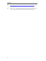
A Fault Scenario Diagrams ...................................................................................... 65
Fault Scenario 1...................................................................................................... 65
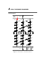
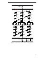
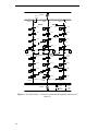
Fault Scenario 2...................................................................................................... 69
B Matlab Simulink Models....................................................................................... 76
C Flowcharts ............................................................................................................. 82
D FIPA Communicative Acts ................................................................................... 85
E User Manual .......................................................................................................... 86
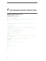
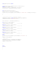
F Java and Matlab Script Source Code................................................................... 88
Embedded Matlab function code............................................................................. 88
Java Source Code ................................................................................................... 89
6
LIST OF FIGURES
Figure 4-1: System overview of the main elements in JADE
Figure 4-2: DF yellow pages service
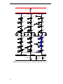
Figure 5-1: Distribution network in normal operation
Figure 6-1: The PRS architecture
Figure 6-2: Layered agent architectures
Figure 6-3: Network diagram with location of agents shown
Figure 6-4: The layered structure of the multi agent system and the control and data
flow between them.
Figure 6-5: Elements of the BusFeederOntology
Figure 6-6: Sequence diagram of the Contract Net Interaction Protocol
Figure 6-7: Sequence diagram of the FIPA Subscribe Protocol
Figure 6-8: Sequence diagram for FIPA Cancel Meta Protocol
Figure 6-9: Finite State Machine diagram of the FSM behavior
Figure 6-10: Flowchart of Finite State Machine Behavior
Figure 6-11: Flowchart for ContractNetInitiator behavior part 1
Figure 6-12: Flowchart for ContractNetInitiator behaviour part 2
Figure 6-13: Flowchart for ContractNetInitiator behavior part 3
Figure 6-14: prepareResponse method of ContractNetReponder
Figure 7-1: Simulation part of fault scenario 1
Figure 7-2: Clearance of fault and subsequent return to normal operation
Figure 7-3: FA1A and FA1C negotiating with FA2A, FA2B and FA2C
Figure 7-4: Simulation result after occurrence of line fault at feeder 2C.
Figure 8-1: An Upper Ontology extended for different power engineering applications
FIPA communicative acts
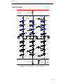
Figure A - 1: Fault Scenario 1: A line fault on feeder 1A
Figure A - 2: Fault Scenario 1: FeederAgent1A prepared for restoration
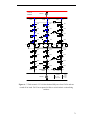
Figure A - 3: Fault scenario 1: Feeder 1A fully restored by 1B and 1C
Figure A - 4: Fault Scenario 1: Clearance of fault and subsequently connection of
switch S1
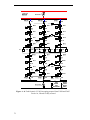
Figure A - 5: Fault Scenario 2: The loss of Source1
Figure A - 6: Fault scenario 2: FA1C has obtained full power from FA2C and FA2B
and connected all its loads
7
List Of Figures
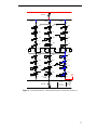
Figure A - 7: Fault scenario 2: FA1A has obtained full power from FA2A and connected all its loads. FA1C has requested its BAs to switch in their sectionalizing
switches.
Figure A - 9: Fault Scenario 2: Line fault at feeder 2C while loss of source 1
Figure A - 10: Fault Scenario 2: FA2C canceling subscription with FA1C
Figure A - 11: Fault Scenario 2: FA1C unable to restore full power and prioritizes its
loads
Figure B - 1: Data transfer between Matlab and JADE
Figure B - 2: Illustration of simple network to test data passing between Matlab and
JADE
Figure B - 3: Simulink model of network with two sources and one load
Figure B - 4: Plot of active and reactive power for SourceB, and SourceC and voltage at
the load
Figure B - 5: Diagram of 6 bus network
Figure B - 6: Simulink model of 6 Bus network
Figure C - 1: handleCancel( ) method of SubscriptionResponder Behaviour
Figure C - 2: SubscriptionInitiator Behaviour
Figure C - 3: Flowchart for BusAgent Cyclic Behavior
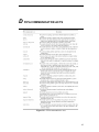
Figure D- 1: FIPA communicative acts
8
LIST OF TABLES
Table 3-1: FIPA Communicative Acts categorized after their usage
Table 5-1: Distance values between the feeders
Table 7-1: Prioritization of buses at a feeder
Table 7-2: Pre-fault load consumption values at each bus for fault scenario 1
Table 7-3: Pre-fault load consumption values at each bus for fault scenario 2
9
List of Abbreviations
LIST OF ABBREVIATIONS
MAS: Multi Agent System
JADE: Java Agent DEvelopment framework
FIPA: Foundation for Intelligent Physical Agents
ACL: Agent Communication Language
DF: Directory Facilitator agent
AMS: Agent Management System
FA: Feeder Agent
BA: Bus Agent
10
1 PREFACE
1.1 Background
During the past years the electric power industry has been seen to move towards more
decentralized generation, changing market operations and more complex distribution
systems. Due to this development, it is increasingly difficult to manage the network
from a central control system. The current centralized SCADA system is not longer sufficient for some control operations [12]. In order to face this development, there is a
need for more a distributed control architecture.
MAS technology provides a solution for creating such distributed control systems.
The focus of this report is the process of service restoration in a power distribution system in particular - that is the restoration of power in a distribution system in case of an
outage. The purpose has been to investigate the potential for applying MAS technology
to solve this restoration problem. The following issues have been addressed in the project:
1.2 Project objectives
• What is the potential and challenges for applying multi agent systems in the restoration of distribution systems?
• What strategy should the individual agents follow to restore the power and how
can the responsibilities be divided between the agents to accomplish the task?
• How can the interaction between a multi agent system and a model of a distribution network be simulated?
1.3 Personal motivation
My personal motivation for carrying out this project has been an interest in acquiring
knowledge about agent systems and the application of agent technology in society.
Furthermore, it is interesting to investigate the application of agent technology to a
power industry application as this industry is undergoing many changes these years in
the way power is generated, traded and distributed. This development opens up new
possibilities for employing technologies like MAS in the industry.
11
Preface
1.4 Method, limitation and background
The focus of this project has been to develop a multi agent system for a power distribution system capable of performing service restoration. The current stage of applying
agent technology in the power industry has been researched. It has been researched
which software tools exists for developing and simulating agent systems. The framework JADE was selected for building the MAS, as this is a software framework suited
specifically for developing agent systems and used by the majority of the agent community today. The JADE platform is described in chapter 4.
The capability of the MAS developed in JADE has been demonstrated by observing
the systems response to two different fault scenarios. A simple distribution network has
been used as basis for the tests.
One of the objectives of this project was to simulate the interaction of the multi
agent system and a model of a physical distribution network. I decided to use Matlab
Simulink to build a model of a physical network, as I am already familiar with this environment. Besides, a connection between Matlab and JADE had been reported successfully in [5]. However, it was not possible to continue the project in this direction, due to
problems encountered with building the Simulink models. This work is described in
appendix C.
Since the purpose of this report is to present a prove of concept of the applicability
of multi agent systems for distribution service restoration, the data used as part of the
case study has been chosed to demonstrate the capabilities of the system. As my background does not lie within power systems, the data used for the network case study may
not be realistic which may limit the applicability of the results of the project.
1.5 Related work
The focus of this project relates to the work done by Nagata et.al. In [4] they propose a
multi agent system approach for service restoration. The work done in this report extends some of the ideas presented in [4] by proposing a prioritization scheme for the
restoration strategy. Furthermore, this report also incorporates the use of FIPA protocols
as described in chapter 6 for the interaction between agents in the MAS.
S&C Electric Company is providing a feeder automation system called IntelliTeam,
which is based on agent technology [8]. In this system control of line segments of the
distribution system is governed teams. Each team consist of an agent called a team
coach which is responsible for negotiating with each team coaches in order to perform
power restoration. Peer-to-peer communication between teams is done through radios
and fiber-optics. The IntelliTeam system has been installed successfully in several distribution networks. However, it should be noted, that this product is not designed according to the FIPA specifications, which is recommended to ease interoperability between multi agent systems.
12
Preface
1.6 How to read the report
This report is divided in eight chapters and four appendices. In Chapter 2 an introduction to service restoration in distribution systems is given. In Chapter 3 I give an overview of the agent paradigm and the specifications layed out by the Foundation for Intelligent Agents (FIPA) to support agent oriented programming. Chapter 4 gives a description of the key elements of the Java Agent DEvelopment Framework (JADE) - the
software platform used for development of the MAS in this project. In Chapter 5 I
briefly present the distribution network used as a basis for testing the MAS, which is
necessary before explaining the MAS design in the following chapter. In Chapter 6 I
describe the design choices I have made during the development of the multi agent system design including the agent architecture, the protocols utilized, as well as a more
detailed description of the software. Chapter 7 presents the fault scenarios used for
testing the operation in the simulations. Chapter 8 presents the results of the tests performed in JADE. In Chapter 9 I summarize what has been carried out during this project as well as future directions of this work. Furthermore, I discuss the future perspectives of employing agent technology in the power industry.
Appendix A contains network diagrams for the two fault scenarios depicting the restoration process. Appendix B gives a description of the work done in this project concerning the connection of the MAS in JADE with a physical model in Matlab Simulink.
Appendix C contains flowcharts associated with the MAS software. Appendix D contains FIPA figures for chapter 3. Appendix E contains a user manual for running the
MAS software and the source code for the MAS and Matlab scripts can be seen in Appendix F.
13
2 INTRODUCTION TO DISTRIBUTION SYSTEM
RESTORATION
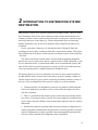
Modern power systems are in general considered to be highly reliable. However, with
the restructuring of the electric power industry towards a market based business environment, pressure to reduce costs has increased, and as a result power systems are operated closer and closer to their limits [6]. This development has led to an increasing
number of blackouts [10]. In case of an outage the utility companies perform service
restoration.
Service restoration is the process of detecting the fault, isolating the fault and
restoring the power to those consumers which have experienced an outage. This project
deals with the part of the process which concerns restoration of power to the consumers
- the loads.
The causes of an outage could be many: Transient faults propagating through the
network, the loss of a power source due to a generator fault, or faulty equipment e.g. the
loss of a transmission line. Transient faults mainly occur in transmission systems, and
most of these faults are cleared by protective systems [9]. Still, some faults turn out to
cause a permanent partial or complete blackout of distribution areas.
The primary objective of service restoration is to restore as many unrestored loads as
possible until the fault is cleared. This is achieved by closing or opening a number of
switches in the network, so power can be rerouted or provided by alternative sources if
necessary. This reconfiguration of the network is subject to several constraints:
• Transmission lines in a distribution system can only transmit a limited amount
of power. It might not be possible to recover some loads in the outage area due to
such line constraints.
• There is a constraint on the amount of power which can be provided by alternative sources. If too many loads are restored, the system might get overloaded resulting in a shift in the power balance of the network and a frequency decrease, which is
undesirable.
• Distribution systems are typically radial structured. During reconfiguration it is
usually important to maintain this network structure as much as possible to keep the
network configuration as simple as possible. Interconnecting different subsystems
will create loops, and make the configuration more complicated.
15
Introduction to Distribution System
Restoration
Since time is a crucial factor during a service restoration, it is desirable to minimize the
number of switching operations required to restore power, as every switching operation
takes time. This objective will however be neglected in this project for the sake of simplicity.
In addition to dealing with the objective of restoring as many loads as possible during an outage, this project will also consider a prioritization of the individual loads.
Due to the above mentioned constraints, it is possible that power to the loads in the
blackout area can not be fully restored. Since it is usually not equally important to maintain service for all loads in a distribution network, a utility company would attempt to
restore power to facilities critical for society first. This could for instance be hospitals,
police stations and governmental agencies etc. [15]. Secondly, the utility would attempt
to restore power to businesses and private consumers. Industrial businesses would have
interest in paying to get prioritized in case of an outage, so utilities could benefit commercially by having customers pay to get prioritized.
A prioritization scheme has been incorporated in the restoration strategy for the
MAS developed during this project, which will be described in chapter 6.
In the next chapter the paradigm which forms the basis for multi agent system development will be described.
16
3
THE AGENT PARADIGM
3.1 Characteristics of an agent
Agent Oriented Programming (AOP) is a software paradigm which brings together concepts of artificial intelligence with distributed systems. In AOP, an application is modeled as a collection of components called agents [1]. The computer science community
has proposed several different definitions of what exactly an agent is. According to
Wooldridge [7], an agent is defined as follows:
“An agent is a computer system that is situated in some environment, and that is capable of autonomous action in this environment in order to meet its design objectives”.
Here the environment defines everything external to the agent. In a power system the
environment would be the physical electric network in which the agent is placed.
Wooldridge extends this definition of an agent by the following characteristics:
• Autonomy: An agent is autonomous because it operates without direct intervention from humans or other agents and has control over its actions and internal state.
This implies that, an agent can decide whether or not to perform an action on request
from another agent.
• Reactivity: An agent is reactive by being able to perceive its environment and
respond to changes in this environment according to its design objectives.
• Proactiveness: An agent has the ability to perform goal directed behavior by
taking the initiative without external stimulus, hence it is not only reactive.
• Social ability: An agent has a social ability because it communicates with other
agents to satisfy its design objectives.
.
.
17
The Agent Paradigm
Having a social ability implies more than just agents passing data to each other. Agents
are capable of negotiating and interacting with each other. This ability is facilitated by
an Agent Communication Language (ACL), which will be described in the following
section.
Furthermore, an agent’s interaction with its peers can be cooperative in order to satisfy a common goal or competitive serving their own interests. In the application of this
project, service restoration, the restoration objective of maximizing the number of restored loads will only be fulfilled if agents are cooperating in achieving this common
goal.
3.2 FIPA Agent Communication Language
One of the essential abilities for agents in multi-agent systems is the ability to communicate. An agent should be able to communicate with the user(s) of the system, system
resources as well as other agents [1]. Communication between agents is based on specific communication languages, called Agent Communication Languages (ACL).
KQML was the first agent communication language to be developed in the 1990s. Currently, the most used agent communication language is the FIPA ACL. FIPA, the Foundation for Intelligent Physical Agents, consists of a collection of academic and industrial organizations. It was established in 1996 to develop a set of standards concerning
software agent technology. These standards were intended to make agent technology
usable on a broad range of applications and thereby form the basis for the commercial
deployment of agent technology [1].
Agent communication languages like FIPA ACL are based on speech act theory. Speech
act theory provides a way to separate the content of a message from the intention of the
message. This is achieved by giving each message a specific performative - or act - besides the actual content delivered with the message. This performative denotes what the
sender of the message want the receiver to do with the contents. An act of a message
could for instance be inform, propose, refuse, agree or not understood. Below is an example of a FIPA ACL message with a request performative. Here, the intention of the
sender of the message is to request the receiver to book a hotel in the period specified in
the content field.
18
The Agent Paradigm
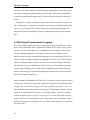
Table 3-1 gives an overview of all performatives of the FIPA Agent Communication
Language. The acts are classified in terms of their usage. The CONFIRM act is information passing, since it is used to inform the receiving agent that something is true. An
agent would for instance use the REQUEST performative to ask another agent to perform some action. This agent would then reply with a CONFIRM performative if it succeeded at performing the action, otherwise it would send a message with a DISCONFIRM performative.
Table 3-1: FIPA Communicative Acts categorized after their usage
A full list of the definition of all FIPA communicative acts can be seen in Appendix A.
19
The Agent Paradigm
3.3 Ontologies
For two agents to communicate about a certain knowledge domain, i.e. a certain topic,
they need to agree on a certain terminology to describe this domain. In other words, if
the domain is a bolt for instance, they need a common understanding of what length,
diameter and thickness of this bolt is. For this, they use ontologies. An ontology is a
formal definition of a body of knowledge [7].
In the Java Agent DEvelopment framework (JADE) an ontology can be composed
of three type of elements: Predicates, Concepts and Agent Actions.
Concepts are structures that consist of things that exist in the world. Some examples
could be the concepts Person and Car:
(Person: name: Jens Jensen age: 30 height: 185)
(Car: manufacturer: Audi model: TT hp: 255 price: 800.000)
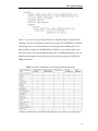
Predicates say something about the relation between concepts. A predicate can be either
true or false. The following predicate indicates that the person Jens is the owner of the
car specified, if predicate Owns is true:
Owns ((Person: name: Jens Jensen age: 30 height: 185) , (Car: manufacturer: Audi
model: TT hp: 255 price: 800.000))
Agent Actions indicate actions to be performed by agents, for instance:
Buy ((Car: manufacturer: Audi model: TT hp: 255 price: 800.000)
, (Person: name: Jens Jensen age: 30 height: 185))
The agent action Buy could be sent to a certain agent, requesting that agent to buy the
car from Jens Jensen.
The use of ontologies in the MAS developed in this project will be described in
chapter 6.
The next chapter a description of the JADE platform will be given, which to a large
extent is built upon the FIPA specifications presented above.
20
The JADE Platform
4 THE JADE PLATFORM
The Java Agent DEvelopment framework, JADE, is considered to be the leading FIPAcompliant open source agent framework [1]. It supports all the main FIPA specifications
described in the previous chapter.
The software development of JADE was started in 1998 by Telecom Italia with the purpose of validating the FIPA specifications and subsequently grew to a full middleware
used to create multi agent systems. JADE consists of a runtime environment to host and
execute agents, a library consisting of Java classes used to create agents, and a graphical
user interface to monitor the activity of executing agents.
In JADE each agent has its own thread of control. Message passing is done asynchronously so there is no dependency between the sending and receiving agent [1]. This
makes the receiving agent able to choose if and when to perform a given action requested by the sending agent. It enables the sending agent to control its own thread of
execution, by not being dependent on an answer from the receiving agent. Such a loose
coupling of agents makes agent systems very fault tolerant. One malfunctioning agent
will not make and entire agent system fail.
Due to the autonomy of each agent it is possible to add and remove agents while an
agent system is running [13]. This is very beneficial when a system has to be upgraded
or extended. New functionality can be added to a system by installing new agents while
the system is online.
A JADE platform is composed of one or more containers. A container is the Java process that provides the JADE run-time and the services needed for hosting and executing
agents [1]. An agent is attached to a certain container. These containers can be hosted
21
The JADE Platform
on the same machine or distributed on a number of machines, as would be the case for
an implementation of a multi agent system in an electrical distribution network.
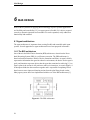
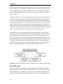
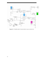
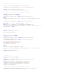
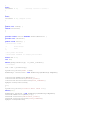
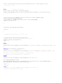
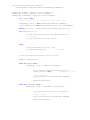
Figure 4-1: System overview of the main elements in JADE
Figure 4-1 shows a system composed of three containers, each with a number of agents,
distributed on three machines. Every agent system requires a main container. A main
container differs from normal containers by taking care of the agent lifecycle management. It provides each agent with a unique name (an Agent Identifier AID) at run-time
and besides that, it holds two special agents: The AMS (Agent Management System)
and DF (Directory Facilitator) agents.
The AMS provides each agent with a unique name, an Agent Identifier (AID). An
agents AID could for instance be peter@1099-laptop where “peter” is the local name on
platform “1099-laptop”. Furthermore, the AMS is responsible for creating and deleting
agents.
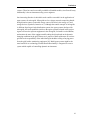
The DF agent provides a yellow pages service to all other agents. By searching the
yellow pages one agent can discover other agents which provide a service it requires to
achieve its goals. An overview is given in figure 4-2.
22
The JADE Platform
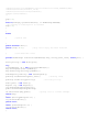
Figure 4-2: DF yellow pages service
As illustrated in the figure, agent A4, A5 and A6 use the yellow pages to search for services published by agent A1, A2 and A3. Agent A5 could for instance be interested in
buying books, a service offered by agent A1, who would then publish this service on the
yellow pages. If the publishing agent A1 decides - for whatever reason - to stop selling
books, it can deregister its services from the yellow pages.
In the next chapter the distribution network used as a case example will be presented,
before moving on to describing the MAS design in the following chapter.
23
The Network Case Study
5 THE NETWORK CASE STUDY
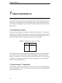
In this chapter the distribution network under study is presented. This distribution network will be used to test and demonstrate the operation of the developed multi agent
system.
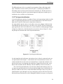
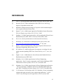
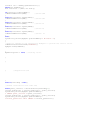
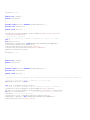
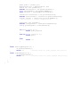
A diagram of the network is shown in Figure 4-1. In the system, power is provided
from two sources, Source1 and Source2, each through a distributed transformer. Each
transformer provides power to three feeders A, B and C, where each feeder includes
four buses each having a load attached. Switches are symbolized with a square symbol
in the diagram, where a black filling denotes that the switch is close while a white filling symbols an open switch.
All feeders are connected with each other making it possible to reconfigurate the
network in numerous ways. Each feeder is connected with the other feeders fed from the
same source through the switches denoted SAB, SBC and SAC. In addition, all feeders
are connected with feeders from the other source though the tie switches T1 –T9. On
each feeder every bus is separated by a switch, making it possible to isolate one or more
buses of the feeder if necessary. In normal operating conditions of the network all these
sectionalizing switches are closed, as shown in the figure.
Transmission lines impose constraints on how much power can be transmitted. For the
sake of simplicity each feeder has been assigned a maximum allowable MW flowing
through it. This will limit the amount of load which can be connected to the feeder in
addition to its own loads. How much a feeder can provide to another feeder then depends on its current load consumption. A power flow capacity of 500 MW will be used
for all feeders in the subsequent simulations.
As mentioned in chapter 2 it is desirable to keep a radial structure in the network during
restoration. This structure can be enforced whenever possible by assigning distances
between the six feeders. The values used for the simulations can be seen in table 5-2.
Say that feeder 1A can be connected with one of the feeders 1B, 1C and 2A. Feeder 1A
should be connected to the feeder closest to it, which according to table 1A is feeder 1B,
with the distance 1. The feeder least desirable for feeder 1A to interconnected to is
feeder 2C with a distance of 5.
.
24
The Network Case Study
Table 5-1: Distance values between the feeders
1A
1B
1C
2A
2B
2C
1A
X
1
2
3
4
5
1B
1
X
1
4
3
4
1C
2
1
X
5
4
3
2A
3
4
5
X
1
2
2B
4
3
4
1
X
1
2C
5
4
3
2
1
X
25
The Network Case Study
Figure 5-1: Distribution network in normal operation
26
The Network Case Study
27
MAS Design
6 MAS DESIGN
Some of the key benefits of applying MAS technology in power systems applications
are flexibility and extensibility [12]. An agent system is flexible if it is able to respond
correctly to dynamic situations and extensible if it can be expanded, easily added new
functionality and modified.
6.1 Agent architecture
The agent architecture is important when creating flexible and extensible multi agent
systems. Several approaches to agent architectures have been proposed in literature.
1.6.1 The BDI architecture
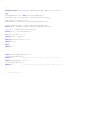
One of them is the Belief-Desire-Intention (BDI) architecture, wherefrom the Procedural Reasoning System (PRS) is a well known extension. The PRS architecture is
based on four data structures: Beliefs, Desires, Intentions and Plans. An agent’s beliefs
represent the information the agent has about its environment, the desires are the agent’s
goals, and intentions represent desires that the agent has committed to achieving [1]. An
agent’s plans is the actions it will perform to achieve its intentions. As seen in figure 6-1
an interpreter binds the data structures together and is responsible for updating beliefs
based on new sensor input and choosing actions from the plan library based on that.
Many agent systems have been implemented with the use of the BDI architectures [1].
Figure 6-1: The PRS architecture
28
MAS Design
The BDI architecture relies on a symbolic representation of the world using modal
logic. If hardware resources of the system are sparse, a symbolic representation of
knowledge can be too slow to meat certain time-constraints [7]. This has led some research to abandon the symbolic representation approach and propose another type of
architecture, the so called layered architecture.
1.6.2 The layered architecture
A layered architecture consists of a number of layers each representing a behavior of the
agent. An agent designed on the basis of a layered architecture is also called a hybrid
agent since it consists of both reactive and proactive behaviors.
An Agent which is purely reactive is only able to react to any changes in their environment and thus does not proactively try to achieve a set of goals. The layered designed
agent typically has lower level behaviors as reactive behaviors which propagate changes
to higher level behaviors, which then decide on an action to choose. Figure 5-1 shows
the principle of horizontal and vertical layered architectures.
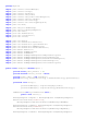
Figure 6-2: Layered agent architectures
In a horizontal layered architecture each software layer is directly connected to the sensor input and the action output i.e. each behavior take in measurements from the environment and decides on some action. A horizontal layer is simple but can lead to complexity as the layers are competing with each other to suggest an action to take. A mediator is then needed to decide which layer has the authority to choose an action [7].
The vertical layered architecture overcomes the problem about authority since sensor inputs are passed from the low level layer and up to higher layers which has the authority to decide on some action. On the other hand, this design is more error prone as
information has to pass through every layer causing the system to fail if one layer fails.
Horizontal layered architectures can be distinguished further in one-pass or two-passed
29
MAS Design
architectures. In a one-pass architecture control flow is directed from a measurement
layer up to the decision layer, which generates an action output itself by the activation
of some actuators. In a two-pass architecture it is the same layer which initially take in
sensor input and performs the control action, decided upon some higher level layer. In
this way, the control flow is going up through all layers at back down again.
6.2 System architecture
The multi agent system architecture and the division of responsibilities between the individual agents, has been built on the work published by Nagata et.al. in [4]. In this paper a distribution system similar to the one used in this project is used as a basis for
demonstration of the MAS. I have decided to design the MAS in a hierarchical way
since such an architecture aligns the most with the structure of the distribution network
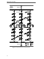
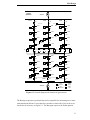
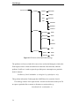
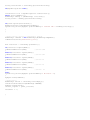
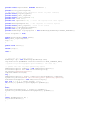
in chapter 5. Figure 6-3 shows the distribution of agents in the distribution network. A
BusAgent (BA) is located at each of the 24 buses. A FeederAgent (FA) is governing
each feeder depicted in the figure as FA1A, FA1B etc. In this way, the MAS developed
in this project, resembles the vertical two-pass layered architecture the most.
30
MAS Design
Normal
Operation
FA1A
Source1
FA1B
S1
FA1B
S5
BA1
BA5
SAC
L
L
S9
BA9
L
S6
S2
S10
BA2
BA6
L
BA10
L
L
S3
S7
S11
BA3
BA7
SBC
L
L
BA11
L
S4
S8
S12
SAB
BA8
BA4
T1
T2
T3
BA12
L
L
T4
L
T5
T6
BA13
T7
T8
T9
BA17
BA21
L
L
L
S21
S17
S13
BA14
BA18
L
BA22
L
S14
L
S18
BA15
S23
BA19
SBC
L
L
S15
BA23
L
S19
S24
SAB
BA16
L
FA2A
S16
BA20
L
FA2B
Source2
BA24
L
S20
SAC
FA2C
S25
Load
connected
Switch
closed
Load
disconnected
Switch
open
Figure 6-3: Network diagram with location of agents shown
The BusAgent represents a particular bus and is responsible for monitoring one or more
loads attached to this bus. It can control two switches on either side of it in order to isolate the bus if necessary, see figure 5-1. The BusAgent reports to the FeederAgent in
31
MAS Design
case of any abnormal system changes, that is if power is not supplied to its load or if
power has been restored. It also receives orders from the FeederAgent to connect or
disconnect its switches or load.
The FeederAgent represents a feeder and is responsible for initiating power negotiations with others feeders on behalf of its BusAgents in case of a power outage. If the
FeederAgent has succeeded in providing power to its BusAgents from another feeder, it
sends a command to the appropriate BusAgent to connect the two feeders.
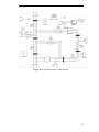
The control flow and information flow between these agents is illustrated in figure 6-3.
As mentioned, BusAgents monitor a number of measurement devices. These include
power flow measurement devices situated at the loads, which continuously measures the
power consumed by the loads. Abnormal system changes in the network, like the loss of
voltage, would be detected by these measurement devices. The BusAgent will then notify its FeederAgent about these changes. If power to the load is lost, it will notify the
FeederAgent about this event a long with the pre-fault power consumption of its load.
The FeederAgent will then decide on an action to take based on the information passed
from several BusAgents. These control actions are then passed down to the appropriate
BusAgents, which will perform the requested action, by controlling its switching devices.
Figure 6-4: The layered structure of the multi agent system and the control and data
flow between them.
As seen from the figure, negotiations can only take place at the decision layer, and not
between BusAgents, which only permit a BusAgent to report to one FeederAgent. Peerto-peer negotiations between BusAgents could be desirable if BusAgents should have
autonomy to provide or request power from other BusAgents. However, if BusAgents
were capable of negotiating with each other it would lead to a substantial increase in
communication among the agents, which would require additional computational re-
32
MAS Design
sources. By gathering information from several BusAgents at one FeederAgent, communication between agents is reduced to a smaller number of agents.
6.3 Ontologies
As outlined in section 3.2 ontologies provides a way to structure information for several
agents to understand it. In this project, an ontology has been created to structure information transferred between BusAgents and FeederAgents. The structure of this ontology, called the BusFeederOntology, is shown in figure 6-4. The ontology consists of
number of concepts, predicates and agent actions.
The concepts represent the elements relevant for the BusAgent that is the physical components surrounding the BusAgent like load, line section and switches. Besides these
concrete things, a fault is also considered a concept, although being abstract. As depicted in the figure each concept can consist of one or more subconcepts. For instance,
the information necessary to describe the status of a load is loadnumber, voltagelevel
and powerlevel.
Predicates offer a way to express the status of the world by indicating the relation between concepts. One responsibility of the BusAgent is to notify the FeederAgent in case
of fault events. This is done with the predicate onLineSection. If a line fault has occurred at line section number 3, the BusAgent will send the following predicate to the
FeederAgent:
onLineSection( (LineSection: sectionnumber 3), (Fault: faulttype linefault) )
Information about the location of a fault and the type of fault is important to the FeederAgent in order to make any conclusions about how many of the BusAgents on the
feeder is affected by the fault.
33
MAS Design
Figure 6-5: Elements of the BusFeederOntology
The predicates isConnected and isDisconnected are used by the BusAgent to inform the
FeederAgent, when a certain switch has been connected or disconnected, while the
predicate NeedPower is used to report the pre-fault power consumption at a particular
load, for instance:
NeedPower( (Load: loadnumber 4, voltagelevel 0, prefaultpower: 40))
This predicate informs the FeederAgent that 40 MW has to be restored to Load 4.
The ontology consists of two agent actions: SwitchIn and SwitchOut used by the FA
to request a particular BA to connect or disconnect a certain switch e.g.:
SwitchIn(Switch: switchnumber 4 )
34
MAS Design
6.4 Protocols
As mentioned above, when a fault occurs on a feeder, the FeederAgent will initiate a
negotiation with one or more feeders to restore the power to its buses. FIPA has standardized the way agents interact in several protocols.
Among those the FIPA Contract Net Interaction Protocol and the FIPA Subscribe Protocol have shown to be to suitable for the MAS developed in this project.
The sequence diagram of the FIPA Contract Net Interaction Protocol is shown in
Figure 5-2. This protocol describes the case of one agent (the initiator), who wishes to
have a task performed by one or more other agents (the participants). The initiator sends
out a Call For Proposal (CFP) message, which specifies the task to be performed, to m
participants. The participants can then choose to submit a proposal to perform the action
or they can refuse. They would typically refuse if they are not able to perform the action
e.g. to provide the amount of power which the initiator requests. The initiator has set up
a deadline for receiving replies and when that is passed, it selects one, more or none of
the proposals received. It might not get any replies at all or only refusals so such situations should be taken care of. In case it gets one or more proposals, it accepts one or
more of them and rejects the rest. A participant which receives an ACCEPT PROPOSAL from the initiator returns an INFORM if the action has been performed successfully or a FAILURE if they fail to. The participants, which proposals the initiator
chooses to accept, is from now on called the contractors.
35
MAS Design
Figure 6-6: Sequence diagram of the Contract Net Interaction Protocol
The FIPA Subscribe Protocol can be used when one agent wants to subscribe on getting
certain information from one or more other agents. The sequence diagram for the Subscribe Protocol in shown in figure 6-6.
36
MAS Design
Figure 6-7: Sequence diagram of the FIPA Subscribe Protocol
In the MAS developed in this project the protocol is used after an initiator has succeeded in finding contractors which can provide power to it. The initiator will then subscribe to get informed by the contractor if any changes occur which affect their agreement. This goes both ways. The subscribing agent, that is the agent which initiated the
Contract Net Interaction Protocol, will cancel the subscription if the fault is cleared in
the network and power has returned. The contractor will likewise cancel the subscription if system changes affect its ability to keep providing the power.
While the sequence diagram in figure 5-3 shows the interaction when setting up a subscription figure 5-4 shows the protocol for cancellation. It is recommended by FIPA to
follow such standards to make interactions less error prone as agents can expect what
kind of reply should receive. When an agent performs a cancellation it expects to get a
reply in form of a INFORM or FAILURE message in order to assure that its message
has actually been received by the right agent.
37
MAS Design
Figure 6-8: Sequence diagram for FIPA Cancel Meta Protocol
6.5 FeederAgent design
Each agent is composed of a number of behaviors. A behavior represents a certain task
to perform. For the FeederAgent class the tasks are divided on the following behaviors:
•
ContractNetInitiator Behavior: This behavior initiates a power negotiation according to the Contract Net Interaction Protocol.
•
ContractNetResponder Behavior: This behavior process any messages received
which is part of the Contract Net Interaction Protocol.
•
SubscriptionInitiator Behavior: This behavior initiates a subscription with another
FeederAgent according to the FIPA Subscribe Protocol.
•
SubscriptionResponder Behavior: This behavior process any message received
with is part of a Subscription Protocol interaction.
•
Fininite State Machine (FSM) Behavior: This behavior is controlling the state of
the FeederAgent. During a reconfiguration the agent goes through different states,
so this behavior can be considered the main behavior.
5.6.1 The use of the DF yellow pages
The DF yellow pages described in chapter 4, will be used in this MAS to enable FeederAgents to publih and search for services they require. For this application the ser vice
a FeederAgent will offer is to provide power to other FeederAgents. This is used when
one FeederAgent has experienced at fault on its feeder. It will then search through the
38
MAS Design
yellow pages for other available FeederAgents which it will initiate a negotiation with
according to the protocol outline above. A FeederAgent will only have its power service
registered in the yellow pages if it is able to deliver power to other FeederAgents. When
a FeederAgent experiences a fault on its feeder and loss of power it will start out deregistering its power service from the yellow pages.
The switching between the above is controlled by a round-robin non-preemptive scheduler of the agent class itself which is hidden by the programmer. It is often that the
above behaviors will wait for receiving a particular message from another agent. In
order to prevent that one behavior will run all the time until the message it needs has
been received, one can use a special block( ) method. The block() method blocks that
behavior from running until the particular has been received, allowing other behaviors
to run.
6.6 Restoration strategy
6.6.1 The Finite State Machine Behavior
A state diagram of the FSM behavior of the FeederAgent class is shown in figure 6-8.
Besides this diagram a flowchart in figure 6-9 describes the same behavior but in a more
detailed manner. The following gives a description of the conditions which leads the
FeederAgent through the different states. The FSM behavior has five states as shown in
figure 6-8.
State 1: The FeederAgent (FA) starts in an idle state, state 1, waiting for notification
messages from any of its BusAgents (BAs), see figure 6-8. If a message is received, the
information sent by the BusAgent is evaluated. If power any power loss at the load is
reported, the FA will store the pre-fault power value. In case several loads are left without power, the FA will add these individual pre-fault consumption values and go to next
state, state2, see figure 6-8.
In a the FA receives notifications from its BAs that power has returned it will stay in
the same state, state1, but register its services on the DF yellow pages since power has
returned. Besides if the FA has done any subscriptions with other FAs during the outage
period it will cancel these and send request to the appropriate BAs to disconnect the
interconnecting switches to these feeders.
In this state, the FA also waits for any subscription cancellations form other FAs.
Flowchart 6-9 gives a clearer picture of the action taking when such a cancel message is
received.
39
MAS Design
State2: In state 2 the behavior ContractNetInitiator() is invoked. The flowchart of this
behavior can be seen in figure 6-10 to 6-12. When the ContractNetBehavior has been
invoked, the FeederAgent will move on to state 3.
State3: In state 3 the outcome of running the ContractNetInitiator behavior is evaluated.
If no power has been obtained, the FA will return to the idle state, state 1. If the required
amount of power has been fully obtained, it will go to state 5. If it has only been possible to restore part of the required power, the FA will attempt to prioritize its loads by
going to state 4 as shown on the figure.
State 4: Based on the amount of power which has been obtained, the FA will decide on
how many of the loads it is possible to restore. It will request each BA to either connect
or disconnect its load. When all BAs have informed the FA that the action has been performed, it will go to state 5, see figure 6-8.
State 5: In this state, the FA will decide on which switch should be connected to get the
power from the contractor. This could be a tie switch or a switch
Depending on from which other FA(s) the power is to be provided, the FA will request
one of its BAs closest to the switch to connect it. When the BAs have informed that the
actions have been performed successfully the reconfiguation is now complete and therefore the FA will return to the idle state, state 1.
40
MAS Design
Figure 6-9: Finite State Machine diagram of the FSM behavior
41
MAS Design
Figure 6-10: Flowchart of Finite State Machine Behavior
6.6.2 The ContracNetInitiator behaviour
The flowchart for the ContractNetInitiator behavior can be seen in figure 6-10, 6-11 and
6.12. When this behavior is invoked by the FSM behavior it starts out searching for reg-
42
MAS Design
istered FAs at the DF yellow pages. If any is found it sends out CFP messages to them,
otherwise the behavior terminates, as seen in figure 6-10. If a message is received before a given deadline it is checked if the message is a proposal, and if this is the case it
is stored in a list. When timeout occurs or all replies has been received, it is checked if
any proposals has been received. If this is the case the next step is to evaluate them,
otherwise the behavior terminates, and the attempt to restore power has been unsuccessful.
Evaluation of the proposals
Figure 6-11 the flowchart for the part of the behavior where proposals are evaluated.
According to the selection criteria based on the distance given in table 5-1, the proposer
which is closest to the initiator is selected. The proposal of this FA is extracted from the
message. If this proposer can deliver the full amount which the initiator requires, the
initiator will accept this and send an ACCEPT PROPOSAL message to the proposer.
Since all power has been obtained the initiator will send an REJECT PROPOSAL message to the rest of the proposals from the list, and go to the next step of the negotiation.
On the other hand, if the proposal is less than what is needed, given by a variable called
power_left, it will accept the full amount proposed and update the power_left variable
with this amount. The power left variable indicates the difference between the power
obtained so far and the power required. As long as this variable is not zero the initiator
will go through the list and find a new proposer. If this proposer can provide an amount
of power greater or equal to the amount which is needed, the initiator will only accept
the amount which is needed. Otherwise it will accept the full amount, update the power
amount obtained so far, and go through the list again. The initiator will go through the
list this way until the full amount of power has been obtained or there are no more proposals in the list.
It will then go to the next step to wait for INFORM messages from the proposers it
has send ACCEPT PROPOSAL messages to as shown in figure 6-11.
43
MAS Design
44
MAS Design
Figure 6-11: Flowchart for ContractNetInitiator behavior part 1
2
Get list of
proposal
messages
Evaluate each proposal
Choose the best proposer
Update power amount
obtained so far
yes
Full amount
obtained?
no
no
proposal >=
power left?
yes
Accept full amount from
best proposer
Accept only amount
needed
Update power amount
obtained so far
Send ACCEPT
PROPOSAL to best
proposer
Remove
proposal
from list
More power
needed and more
proposals?
no
Send
REJECT_PROPOSALS
to remaining proposers
on the list
3
Figure 6-12: Flowchart for ContractNetInitiator behaviour part 2
45
MAS Design
3
Reply received?
yes
no
Got INFORM
message?
yes
Update powertransfer
variable
no
SubscriptionInitiator()
no
Increment no. of replies
received
1
Got all replies?
yes
end
Figure 6-13: Flowchart for ContractNetInitiator behavior part 3
46
MAS Design
6.6.3 The ContractNetResponder Behavior
The ConctractNetResponder behavior consists of a set of methods to handle messages
part of a Contract Net Interaction Protocol. Each method handles specific messages as
CFP, INFORM etc. For this application, the method prepareResponse is the most interesting, as it evaluates incoming CFP messages from other FeederAgents.
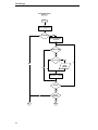
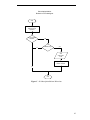
Figure 6-13 shows the flowchart for the prepareResponce( ) method of the ContractNetResponder behaviour. This method is invoked whenever the agent receives a
Call For Proposal message. The FA will measure the current power flow on the feeder that is the collective power consumption of its loads if it is not interconnected with other
feeders. It will then calculate its excess capacity which is the difference between its
maximum allowable power flow and its current power flow. If it has not reached its
limit, it will evaluate the CFP message received, otherwise it will send a refusal to the
initiator. If the requested power value exceed its excess capacity it will propose only
what is possible, otherwise it will propose the full amount requested by the initiator.
47
MAS Design
ContractNetResponder.prepareResponse()
of FeederAgent
start
Measure current
power flow on feeder
Calculate excess
capacity on feeder
Excess capacity >0?
yes
no
Send refusal to
initiator
Extract power value
requested
no
Requested value >
excess capacity?
Propose amount
requested by initiator
yes
Propose available
excess capacity
start
Figure 6-14: prepareResponse method of ContractNetReponder
Flowcharts for the rest of the behaviors which is part of the FeederAgent class can be
seen in Appendix C. Besides the flowchart of the BusAgent class can also be found in
this appendix.
48
MAS Design
49
Simulation Results
7 SIMULATION RESULTS
In this chapter the fault scenarios used to test the MAS and the results of the tests will
be presented. The system has been tested with two fault scenarios: One single fault scenario and one multiple fault scenario. Illustrations of the network configuration at different stages of reconfiguration process can be found in Appendix B for each of the two
fault scenarios.
7.1 Prioritization scheme
The prioritization assigned to each load on a feeder is shown in table 7-1. This prioritization will be used by the FeederAgent in case power can not be fully restored. The FA
will then request the BAs to either connect or disconnect their loads depending on how
what priority their loads have and how much power has been obtained.
Table 7-1: Prioritization of buses at a feeder
Bus
Loadpriority
1
2
1
2
3
4
2
3
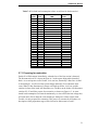
Two different data sets with pre-fault load consumption values have been assigned for
each scenario. Table 7-2 shows the pre-fault load consumption values used for fault
scenario 1, while table 7-3 shows the data set used for fault scenario 2. These values are
considered to be instantaneous and represent the consumption at each load at that particular time when the fault occurs.
7.2 Fault scenario 1: Single fault
The first fault scenario to be considered is a line fault on feeder 1A as illustrated in figure A-2 in appendix A. Table 7-2 shows the data used for pre-fault load consumption at
each bus for this scenario.
50
Simulation Results
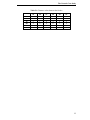
Table 7-2: Pre-fault load consumption values at each bus for fault scenario 1
Feeder
1A
1B
1C
2A
2B
2C
Bus
1
2
3
4
5
6
7
8
9
10
11
12
13
14
15
16
17
18
19
20
21
22
23
24
Load consumption
(MW)
60
90
50
50
70
80
60
70
70
50
80
90
90
70
60
80
40
90
40
50
60
70
90
40
MW on
feeder
250
280
290
300
220
260
2.7.1 Preparing for restoration
Switch S1 will disconnect immediately, when the loss of the line section is detected.
The disconnection of S1 is shown in figure A-3 as the square being white instead of
black. As a result power to all of feeder 1A is now lost, denoted by a blue line. As BA1
is monitoring S1, it will record the system change and notify FA1A about the fault
event. When S1 has disconnected, voltage at all loads on feeder 1A is lost, and the
switches in front of the loads will disconnect too. The BAs on the feeder will disconnect
switches S2, S3 and S4 to prepare for restoration, as shown on figure A-3. As mentioned load consumption is measured continuously, so since all BA has lost voltage they
will each notify FA1A about the event and the pre-fault power values at their loads.
Feeder1A is now prepared for restoration. This process is common for all feeders so a
description of this preparation stage will be left out for fault scenario 2 and 3.
51
Simulation Results
2.7.2 Restoration process
When all sectionalizing switches of the feeder are disconnected the feeder has been prepared for restoration. Then FA1A will start in state 1 by receiving notifications from all
its BAs, which is left without power. In this scenario all BAs are affected so the total
power which has to be restored to feeder 1A is 250 MW. When notifications from all
BAs have been received FA1A starts searching for other FAs.
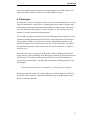
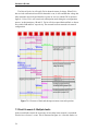
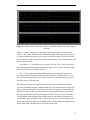
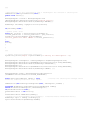
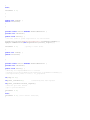
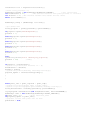
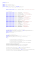
Figure 8-1 shows part of the simulation of the restoration process. As seen from the
figure, FA1A will start searching for registered FAs through the DF yellow pages. Since
feeder 1A is the only feeder having a fault, all other FAs are registered. It then sends
CFP messages out to these FAs requesting 250 MW. Since the current power level at
feeder 1B and 1C is 280 MW and 290 MW respectively, FA1B proposes to deliver 220
MW, while FA1C propose to deliver 210 MW. After evaluating the proposals FA1A
choose to accept the 220 MW from FA1B since feeder 1B is closest to feeder 1A, and
the remaining 30 MW from FA1C. The rest of the proposals are rejected. Since FA1A
has obtained the full amount required, it requests all its BAs to switch in their loads.
In the next step of the process, which is not shown on the figure, FA1A requests
BA1 and BA4 to switch in SAB and SAC respectively in order to connect feeder 1A to
feeder 1B and 1C. The pre-fault power at feeder 1A has now been fully restored, as
shown in figure A-4.
52
Simulation Results
Figure 7-1: Simulation part of fault scenario 1
At some time t after the reconfiguration, the fault at feeder 1A is cleared. Through its
measurement devices BA1 will detect the return of voltage at this line section, and connect switch S1. This situation is shown in Figure A-5. All loads downstream of S1 will
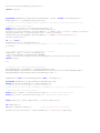
now sense the return of voltage and notify FA1A. Figure 8-2 shows the simulation result from the time when the fault is cleared.
53
Simulation Results
The BAs of feeder 1A will notify FA1A about the return of voltage. When FA1A
has received notification from all BAs about this event, it will conclude that voltage has
fully returned to the feeder and therefore register its services with the DF as shown in
figure 8-2. Next, FA1A will cancel each subscription made during the reconfiguration
process, in this situation to 1B and 1C. FA1A will also request BA4 and BA1 to disconnect switch SAB and SAC respectively. The network has now returned to its normal
configuration.
Figure 7-2: Clearance of fault and subsequent return to normal operation
7.3 Fault Scenario 2: Multiple faults
In the second fault scenario the occurrence of two faults in the network is considered.
First the loss of source 1 occurs. This is illustrated in figure A-6. After this fault a sec-
54
Simulation Results
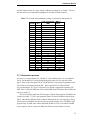
ond line fault at feeder 2C occurs, which is illustrated in figure A-10. Table 7-3 shows
the data used for pre-fault load consumption at each bus for fault scenario 2.
Table 7-3: Pre-fault load consumption values at each bus for fault scenario 2
Feeder
1A
1B
1C
2A
2B
2C
Bus
1
2
3
4
5
6
7
8
9
10
11
12
13
14
15
16
17
18
19
20
21
22
23
24
Load consumption
(MW)
60
50
80
40
50
80
40
60
40
50
100
100
50
70
60
70
40
70
40
50
80
70
90
60
MW on
feeder
230
230
290
250
200
300
3.7.1 Restoration process
As source 1 is lost the feeders 1A, 1B and 1C is left without power. As a consequence
FA1A, FA1B and FA1C start by deregistering their power service from the yellow
pages. Thus, each of the agents FA1A, FA1B and FA1C only initiate negotiations with
FAs which are still registered at the DF - that is agent FA2A, FA2B and FA2C.
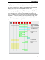
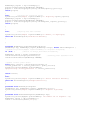
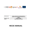
As seen from figure 8-5, FA1C is the first FA to initiate a negotiation requesting 290
MW. FA1C accept 200 MW from FA2C and 90 MW from FA2B since these feeders are
closest to feeder 1C.
The next FA which sends out CFP messages is FA1A which requests 230 MW to be
restored, see table 7-3. FA1A gets proposals from FA2A and FA2B but a refusal from
FA2C, since this FA has just made a contract delivering all its excess capacity to FA1C.
FA2A proposes 250 MW since the current power flow at feeder 2A is 250 MW. FA2B
proposes only 210 MW since it has transferred 90 MW to FA1C of its initial 300 MW
excess capacity. FA1A accepts 230 MW from FA2A since this feeder is closest.
55
Simulation Results
The last FA to initiate negotiations is FA1B requesting 230 MW. FA2A and FA2B
submit a proposal of their excess capacity which is 210 MW and 20 MW respectively.
This is what is required by FA1B to restore its loads.
Figure 7-3: FA1A and FA1C negotiating with FA2A, FA2B and FA2C
According to the scenario outlined in the previous chapter, a fault on feeder 1C occurs
after the loss of source 1.
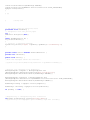
Figure 8-4 shows the result after FA2C has been notified by its BAs that they have
lost power. When FA2C has received the notifications from its BAs it deregisters from
56
Simulation Results
the yellow pages and cancels all its subscriptions, in this case only one made with FA1C
of 200 MW. Afterwards, it searches for available FAs and sends out CFP messages to
the only to FAs registered, FA2A and 2B. As seen from the figure it gets refusals from
both FAs since they both have already reached their power flow limits.
FA1C is in the idle state, state 1, when it gets the cancellation message from FA2C.
It requests the appropriate BA, in this case BA12, to disconnect the tie switch T9. As it
now needs to restore 200 MW of power it goes to state 2 and initiates negotiations with
FA2A and FA2B. As FA2C, it only receives refusals. It only has a contract left with
FA2B on 90 MW and is forced to prioritize its loads. The power values to be restored at
its loads are 40, 50, 100 and a 100 MW for BA1 to BA4 respectively, see table 7-4. According to the prioritization of the four loads in table 7-1 it keeps BA1 and BA2 connected, while it sends out requests to BA3 and BA4 to disconnect their loads, since the
power contract left with FA2B is on only 90 MW.
57
Simulation Results
Figure 7-4: Simulation result after occurrence of line fault at feeder 2C.
The process of returning to the normal configuration when the fault is cleared, in this
case the return of voltage at source 1 and the clearance of the line fault at feeder 1C, is
the same way as in fault scenario 1, so this is not described further.
The restoration process of fault scenario 2 has been illustrated in figure A-6 to A-12
in Appendix A.
In general the simulation results show that the software performs as expected. The timing in the interaction is nevertheless very important for how the scenario turns out.
58
Conclusion
8
CONCLUSION
8.1 Results
In this report an approach for applying agent technology to service restoration of a distribution network has been presented. A restoration strategy for prioritizing certain loads
in case of shortage of alternative sources has been proposed.
A multi agent system has been built using the JADE framework, to verify the restoration strategy. Two fault scenarios have been considered to verify the capability of the
MAS. The test results demonstrates the flexibility of the MAS, in terms of dealing with
different types of network faults occurring one at a time or simultaneously.
This project has incorporated ontologies and FIPA protocols in the multi agent system. It has been shown how the FIPA Contract Net Interaction Protocol and the FIPA
Subscribe Protocol can be used by agents to transfer power between feeders during the
restoration process. The Subscribe Protocol has been useful in the agent design, in order
to keep trach of a FeederAgents power contracts with other FeederAgents.
An ontology for exchanging information between BusAgents and FeederAgents has
been proposed. Although being a simple ontology it shows how agents can notify each
other about events in their environment in a more structured manner than sending plain
text strings.
Furthermore, the potential for simulating a multi agent system behaviour linked to a
physical model in Matlab Simulink has been investigated. A connection between an
agent system in JADE and a Matlab Simulink model has been setup, which allows
measurement data to be transferred from Simulink and control commands to be sent
from JADE to Matlab.
8.2 Perspectives
MAS technology has attracted a great deal of attention from the power system community since it could solve a number of the challenges faced by the industry today.
As multi agent systems is based on a distributed architecture, where each agent take
decisions based of its local information, multi agent systems can relieve the computational burden of centralized control systems employed in current power systems. Besides as it can offer systems with a flexible and extensible architecture.
59
Conclusion
Despite the potential of applying MAS technology in the power industry the implementation of such system in the industry on larger scale has yet to come. Practical experience in implementing agent systems in the industry is still low, and more experience in
producing industrial agent systems in general as well as specifically for the power industry is needed.
A significant barrier for a wide spread adoption of agent systems in the power industry
is the lack of standards to enable the interoperability between different multi agent systems. Such set of standards has been in other areas as the IEC 61850 which promotes
the interoperability between devices within substations [part 2] and the Common Information Model (CIM) which standardizes the way energy management systems can interface with each other. In this regard, FIPA would be an appropriate organization to set
standards for agent system interoperability, as the organization has already set standards
for the way agents should interact, through the FIPA interaction protocols.
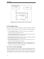
One important aspect of multi agent design is the ontology design. Currently, when a
multi agent system is developed the ontology is application specific. This prevents interoperability between two different agent systems. To solve this problem Catterson
et.al. [14] propose to create an Upper Ontology, which should contain the basics of the
power engineering domain i.e. concepts common to all applications within the domain.
The Upper Ontology could then be extended by developers of different applications
within the domain, see figure 9-1. Having a standard ontology would ensure that developers are representing things like transformer and substation the same way.
Figure 8-1: An Upper Ontology extended for different power engineering applications
8.3 Further work
This project could be extended by investigating alternative simulation environments
which is suitable to use in combination with JADE in order to verify the operation of a
MAS. Matlab has some limitations for this purpose but PowerFactory might be more
suitable. Using PowerFactory would enable one to use many existing models of power
60
Conclusion
systems. These have not been readily available as Simulink models, since PowerFactory
traditionally is the environment used by power engineers.
One interesting direction in which this work could be extended is in the application of
agent systems for microgrids. Microgrids are low voltage networks comprising distributed generation sources (renewable energy sources like wind, solar energy etc.) and
storage devices (flywheels, batteries etc.). Although the control concepts of microgrids
is different from larger feeder distribution systems, the agent systems developed for
microgrids will need capabilities similar to the agent system developed in this project.
Agents will need to represent equipment in the microgrid, for instance a wind turbine,
and monitor the state of the equipment while taking decisions based on the dynamic
changing conditions in the grid. Dimeas et.al. propose a MAS architecture for a microgrid where the responsibility of the individual agent includes selling or buying power
from the grid, besides monitoring equipment [16]. Multi agent systems might be the
most beneficial as a technology when different functionality is integrated to create a
system which capable of controlling dynamic environments.
61
REFERENCES
[1]
Caire, G., Developing Multi-Agent Systems with JADE, Wiley & Sons, 2007.
[2]
Staszesky D. et.al., Feeder Automation is Here, IEEE Power and Energy
Magazine, September/October 2005.
[3]
Riedmiller, Reinforcement Learning for Cooperative and Communicating Reactive Agents in Electrical Power Grids,
[4]
Nagata, T. et.al., A Multi-Agent Approach to Distribution System Restoration,
Electrical Engineering in Japan, Vol. 152, No. 3, 2005.
[5]
Gualdron, J., A Multi-Agent Approach for a Self-reconfigurable Electric Power
Distribution System, MSc. Thesis, University of Puerto Rico, 2006.
[6]
Lin, Z et.al., Power System Restoration in a Restructured Power Industry
[7]
Wooldridge, M., An Introduction to MultiAgent Systems, Wiley & Sons, 2002.
[8]
http://www.sandc.com/products/intelliteam/default.asp, 27th July 2008.
[9]
Webster, J., Power System Restoration, Wiley Encyclopedia of Electrical and
Electronics Engineering, Wiley & Sons, 1999.
[10]
R., Feuillet et. al., Analysis and control of a temporary overvoltages for automated restoration planning, IEEE Trans. Power Delivery, vol. 17, no. 4, Oct.
2002.
[11]
Inagaki, J. et.al., A Multi-Objective Service Restoration Method for Power
Distribution Systems, IEEE, 2002.
[12]
McArthur, S. et.al., Multi-Agent Systems for Power Engineering
Applications—Part I: Concepts, Approaches, and Technical Challenges, IEEE
Transactions on Power Systems, Vol. 22, No. 4, November 2007
[13]
McArthur, S. et.al., Multi-Agent Systems for Power Engineering Applications
– Part II: Technologies, Standards, and Tools for Building Multi-Agent Systems, IEEE Transactions on Power Systems, Vol. 22, No. 4, November 2007.
[14]
V. M. Catterson, E. M. Davidson, and S. D. J. McArthur, “Issues in integrating
existing multi-agent systems for power engineering applications,” in Proc.
13th Int. Conf. Intelligent Systems Application to Power Systems, 2005.
63
Conclusion
[15]
http://www.cwlp.com/electric_division/t_d/power_restore_priority.htm, 1st of
august, 2008
[16]
Dimeas, et.al., A Multi-Agent System for Microgrids, National Technical University of Athens, Department of Electrical and Computer Engineering
64
A FAULT SCENARIO DIAGRAMS
Fault Scenario 1
Normal
Operation
FA1A
Line
fault
Source1
FA1B
S1
FA1B
S5
BA1
BA5
SAC
L
L
S9
BA9
L
S6
S2
S10
BA2
BA6
L
BA10
L
L
S3
S7
S11
BA3
BA7
SBC
L
L
BA11
L
S4
S8
S12
SAB
BA8
BA4
T1
T2
T3
BA12
L
L
T4
L
T5
T6
BA13
T7
T8
T9
BA17
BA21
L
L
L
S21
S17
S13
BA14
BA18
L
BA22
L
S14
L
S18
BA15
S23
BA19
SBC
L
L
S15
BA23
L
S19
S24
SAB
BA16
L
FA2A
S16
BA20
L
FA2B
Source2
BA24
L
S20
SAC
FA2C
S25
Load
connected
Switch
closed
Load
disconnected
Switch
open
Figure A - 1: Fault Scenario 1: A line fault on feeder 1A
Figure A - 2: Fault Scenario 1: FeederAgent1A prepared for restoration
66
Source1
FA1A
FA1B
S1
FA1C
S5
BA1
BA5
SAC
L
L
S9
BA9
L
S6
S2
S10
BA2
BA6
L
BA10
L
L
S3
S7
S11
BA3
BA7
SBC
L
L
BA11
L
S4
S8
S12
SAB
BA8
BA4
T1
T2
T3
BA12
L
L
T4
L
T5
T6
BA13
T7
T8
T9
BA17
BA21
L
L
L
S17
S13
BA14
S21
BA18
L
BA22
L
S14
L
S18
BA15
S23
BA19
SBC
L
L
S15
BA23
L
S19
S24
SAB
BA16
L
FA2A
S16
BA20
L
FA2B
Source2
BA24
L
S20
SAC
FA2C
S25
Load
connected
Switch
closed
Load
disconnected
Switch
open
Figure A - 3: Fault scenario 1: Feeder 1A fully restored by 1B and 1C
67
Source1
Fault
cleared
FA1A
FA1B
S1
FA1C
S5
BA1
BA5
SAC
L
L
S9
BA9
L
S6
S2
S10
BA2
BA6
L
BA10
L
L
S3
S7
S11
BA3
BA7
SBC
L
L
BA11
L
S4
S8
S12
SAB
BA8
BA4
T1
T2
T3
BA12
L
L
T4
L
T5
T6
BA13
T7
T8
T9
BA17
BA21
L
L
L
S21
S17
S13
BA14
BA18
L
BA22
L
S14
L
S18
BA15
S23
BA19
SBC
L
L
S15
BA23
L
S19
S24
SAB
BA16
L
FA2A
S16
BA20
L
FA2B
Source2
BA24
L
S20
SAC
FA2C
S25
Load
connected
Switch
closed
Load
disconnected
Switch
open
Figure A - 4: Fault Scenario 1: Clearance of fault and subsequently connection of
switch S1
68
Fault Scenario 2
Loss of
Source1
FA1A
Source1
FA1B
S1
FA1B
S5
BA1
BA5
SAC
L
L
S9
BA9
L
S10
S6
S2
BA2
BA6
L
BA10
L
L
S3
S7
S11
BA3
BA7
SBC
L
L
BA11
L
S4
S8
S12
SAB
BA8
BA4
T1
T2
T3
BA12
L
L
T4
L
T5
T6
BA13
T7
T8
T9
BA17
BA21
L
L
L
S17
S13
BA14
S21
BA18
L
BA22
L
S14
L
S18
BA15
S23
BA19
SBC
L
L
S15
BA23
L
S19
S24
SAB
BA16
L
FA2A
S16
BA20
L
FA2B
Source2
BA24
L
S20
SAC
FA2C
S25
Load
connected
Switch
closed
Load
disconnected
Switch
open
Figure A - 5: Fault Scenario 2: The loss of Source1
69
Figure A - 6: Fault scenario 2: FA1C has obtained full power from FA2C and FA2B
and connected all its loads
70
Loss of
Source1
FA1A
Source1
FA1B
S1
FA1C
S5
BA1
BA5
SAC
L
L
S9
BA9
L
S6
S2
S10
BA2
BA6
L
BA10
L
L
S3
S7
S11
BA3
BA7
SBC
L
L
BA11
L
S4
S8
S12
SAB
BA8
BA4
T1
T2
T3
BA12
L
L
T4
L
T5
T6
BA13
T7
T8
T9
BA17
BA21
L
L
L
S17
S13
BA14
S21
BA18
L
BA22
L
S14
L
S18
BA15
S23
BA19
SBC
L
L
S15
BA23
L
S19
S24
SAB
BA16
L
FA2A
S16
BA20
L
FA2B
Source2
BA24
L
S20
SAC
FA2C
S25
Load
connected
Switch
closed
Load
disconnected
Switch
open
Figure A - 7: Fault scenario 2: FA1A has obtained full power from FA2A and connected all its loads. FA1C has requested its BAs to switch in their sectionalizing
switches.
71
Figure A - 8: Fault Scenario 2: FA1B accepting proposal from FA2B and FA2C.
Feeder 1A, 1B and 1C fully restored
72
Source1
FA1A
FA1B
S1
FA1B
S5
BA1
BA5
SAC
L
L
S9
BA9
L
S10
S6
S2
BA2
BA6
L
BA10
L
L
S3
S7
S11
BA3
BA7
SBC
L
L
BA11
L
S4
S8
S12
SAB
BA8
BA4
T1
T2
T3
BA12
L
L
T4
L
T5
T6
BA13
T7
T8
T9
BA17
BA21
L
L
L
S17
S13
BA14
S21
BA18
L
BA22
L
S14
L
S18
BA15
S23
BA19
SBC
L
L
S15
BA23
L
S19
S24
SAB
BA16
L
FA2A
S16
BA20
L
FA2B
Source2
BA24
L
S20
SAC
FA2C
Line
fault
S25
Load
connected
Switch
closed
Load
disconnected
Switch
open
Figure A - 9: Fault Scenario 2: Line fault at feeder 2C while loss of source 1
73
Source1
FA1A
FA1B
S1
FA1B
S5
BA1
BA5
SAC
L
L
S9
BA9
L
S6
S2
S10
BA2
BA6
L
BA10
L
L
S3
S7
S11
BA3
BA7
SBC
L
L
BA11
L
S4
S8
S12
SAB
BA8
BA4
T1
T2
T3
BA12
L
L
T4
L
T5
T6
BA13
T7
T8
T9
BA17
BA21
L
L
L
S17
S13
BA14
S21
BA18
L
BA22
L
S14
L
S18
BA15
S23
BA19
SBC
L
L
S15
BA23
L
S19
S24
SAB
BA16
L
FA2A
S16
BA20
L
FA2B
Source2
BA24
L
S20
SAC
FA2C
S25
Load
connected
Switch
closed
Load
disconnected
Switch
open
Figure A - 10: Fault Scenario 2: FA2C canceling subscription with FA1C
74
Source1
FA1A
FA1B
S1
FA1B
S5
BA1
BA5
SAC
L
L
S9
BA9
L
S10
S6
S2
BA2
BA6
L
BA10
L
L
S3
S7
S11
BA3
BA7
SBC
L
L
BA11
L
S4
S8
S12
SAB
BA8
BA4
T1
T2
T3
BA12
L
L
T4
L
T5
T6
BA13
T7
T8
T9
BA17
BA21
L
L
L
S21
S17
S13
BA14
BA18
L
BA22
L
S14
L
S18
BA15
S23
BA19
SBC
L
L
S15
BA23
L
S19
S24
SAB
BA16
L
FA2A
S16
BA20
L
FA2B
Source2
BA24
L
S20
SAC
FA2C
S25
Load
connected
Switch
closed
Load
disconnected
Switch
open
Figure A - 11: Fault Scenario 2: FA1C unable to restore full power and prioritizes its
loads
75
B MATLAB SIMULINK MODELS
In this appendix the work carried out during the project concerning the connection of
Matlab and JADE will be described.
In order to pass data from a Simulink model to an external program, an embedded Matlab function is used. Embedded Matlab functions can be connected to any other block in
a Simulink model. They can include normal Matlab code as in regular Matlab function
scripts - although with some restrictions. In this project they were used to take data from
a model in Simulink and send it to JADE. This were done by setting up a TCP IP clientserver socket, where Matlab functions as a client and JADE as a server. This process is
illustrated in figure B-1. Some of the Embedded Matlab function blocks were used only
to take data (measurements) from the Simulink to the MAS in JADE, like the load and
source embedded function blocks. The negotiation takes places between the corresponding agents in JADE as a control action is passed back to a breaker embedded function
block in Simulink, see figure.
Figure B - 1: Data transfer between Matlab and JADE
A simple network was built in Simulink to test the interaction between the MAS in
JADE and this model. An illustration of this network is seen in figure B-2. The network
76
consists of two voltage sources, a load and two breakers. One of voltage sources, source
B, is simulated to fail in the Simulink model. Since data is sent continuously to the
agents in JADE, this event will be detected and the breaker S5 will be switched in to
restore voltage to the load from the secondary source C.
Figure B - 2: Illustration of simple network to test data passing between Matlab and
JADE
The printout of the Simulink model of this network is shown in figure B-3. Embedded
matlab function blocks are highlighted with colours. The blue blocks are the embedded
function blocks measuring the voltage at source C and B and sending these values to
JADE. The purple block measures the power flow at the load and sends this data to the
LoadAgent in JADE.
A timer cuts off power to voltage source B at time t = 0.1. The loss of voltage is
measured by source B embedded function block, which disconnects switch S3. Power to
the load is now cut off. When the LoadAgent in JADE receives power values approaching zero, it starts requesting SourceAgentC to restore its nominal power. SourceAgent C
accepts this and sends a command to the BreakerAgent which in turn pass a value to the
breaker embedded function block, shown in green, to connect the switch S5. Power has
now been restored to the load by source C.
77
Figure B - 3: Simulink model of network with two sources and one load
78
Figure B - 4: Plot of active and reactive power for SourceB, and SourceC and voltage at
the load
Figure C-2 shows voltage plot for the load as well as power plots for source B and
source C. The voltage for the load is shown in the top plot while the power for source C
is shown in middle plot and power for source B in the lowest plot. The yellow line denotes real power while the purple line denotes reactive power. The simulation time has a
duration of 0.2 seconds.
At the time t = 0.1 second the power at source B is lost. This is seen by the yellow
line in the bottom plot decreasing towards zero after t = 0.1 s. At the same time voltage
is lost at the load as seen from the top plot.
At t = 0.18 seconds, the embedded function block controlling the switch has received data from JADE and the switch is connected source C with the load. It is seen
from the top plot that voltage returns when switch S5 is connected and the power produced by source C also increases.
After having setup this very simple control of a test circuit in Matlab from JADE, I
moved on to building a bigger Simulink model of a 6 bus network shown in figure B-5.
This network consists of several generators and loads. The purpose of connecting this
model to a MAS in JADE, was the potential of controlling the setpoints of generator
blocks in the Simulink model from the agents in JADE. However, problems encountered in Matlab when building bigger models based on asynchronous generators prevented further work in that direction. It turned out not to be possible to change the setpoints of the generators while the simulation where running, which was required if any
agents from JADE should be able to reconfigure the network.
79
Figure B - 5: Diagram of 6 bus network
80
Figure B - 6: Simulink model of 6 Bus network
81
C
FLOWCHARTS
Figure C - 1: handleCancel( ) method of SubscriptionResponder Behaviour
82
SubscriptionInitiatior
Behaviour of FeederAgent
start
Send subscription
message to the
contractor
Any reply within
timeout?
yes
no
AGREE msg?
yes
Add
subscription
to list
Update the power
transfer variable
no
end
Figure C - 2: SubscriptionInitiator Behaviour
83
Figure C - 3: Flowchart for BusAgent Cyclic Behavior
84
D FIPA COMMUNICATIVE ACTS
Figure D- 1: FIPA communicative acts
85
E USER MANUAL
This appendix contains a guide on setting up and executing the MAS software in JADE.
The Java class files and Matlab models and scripts are contained on the CD-ROM accompanying this report.
The multi agent system was developed using Java Development Kit 6.0, Eclipse 3.3.1.1.
The Matlab Simulink models were developed using Matlab 7.5.0.
Before JADE can be started the system path has be set to point to the folders containing
the appropriate classes. This can be done in several. The simplest is to use a batch file to
specify the path.
On the CD-ROM, the batch file are located at the directory /…/Code/Agents/bin.
1. Go to that directory and open the classpath_jadetext.txt file. Modify this file to correspond to your directory placements. Save the file as a bath file.
2. Start a command prompt. Go to the directory /…/Code/Agents/bin.
3. Fill in setup inputs for one of the two scenarios and press enter.
For fault scenario 1 paste the following text into the prompt:
java jade.Boot -detect-main false -gui BusProxy1B1C:Agents.SocketProxyAgent1
BusProxyBottom:Agents.SocketProxyAgent1
BusProxy1A:Agents.SocketProxyAgent1 BusAgent1:Agents.BusAgent1 BusAgent2:Agents.BusAgent2 BusAgent3:Agents.BusAgent3 BusAgent4:Agents.BusAgent4 BusAgent5:Agents.BusAgent5 BusAgent6:Agents.BusAgent6 BusAgent7:Agents.BusAgent7 BusAgent8:Agents.BusAgent8 BusAgent9:Agents.BusAgent9 BusAgent10:Agents.BusAgent10 BusAgent11:Agents.BusAgent11 BusAgent12:Agents.BusAgent12 BusAgent13:Agents.BusAgent13 BusAgent14:Agents.BusAgent14 BusAgent15:Agents.BusAgent15 BusAgent16:Agents.BusAgent16 BusAgent17:Agents.BusAgent17 BusAgent18:Agents.BusAgent18 BusAgent19:Agents.BusAgent19 BusAgent20:Agents.BusAgent20 BusAgent21:Agents.BusAgent21 BusAgent22:Agents.BusAgent22 BusAgent23:Agents.BusAgent23 Bu-
86
sAgent24:Agents.BusAgent24 FeederAgent1A:Agents.FeederAgent1A FeederAgent1B:Agents.FeederAgent1B FeederAgent1C:Agents.FeederAgent1C FeederAgent2A:Agents.FeederAgent2A FeederAgent2B:Agents.FeederAgent2B FeederAgent2C:Agents.FeederAgent2C
For fault scenario 2 paste the following code into the prompt:
java jade.Boot -detect-main false -gui BusProxy2C:Agents.SocketProxyAgent1
BusProxy1B1C:Agents.SocketProxyAgent1 BusProxy1A:Agents.SocketProxyAgent1
BusProxyBottom:Agents.SocketProxyAgent1 BusAgent1:Agents.BusAgent1 BusAgent2:Agents.BusAgent2 BusAgent3:Agents.BusAgent3 BusAgent4:Agents.BusAgent4 BusAgent5:Agents.BusAgent5 BusAgent6:Agents.BusAgent6 BusAgent7:Agents.BusAgent7 BusAgent8:Agents.BusAgent8 BusAgent9:Agents.BusAgent9 BusAgent10:Agents.BusAgent10 BusAgent11:Agents.BusAgent11 BusAgent12:Agents.BusAgent12 BusAgent13:Agents.BusAgent13 BusAgent14:Agents.BusAgent14 BusAgent15:Agents.BusAgent15 BusAgent16:Agents.BusAgent16 BusAgent17:Agents.BusAgent17 BusAgent18:Agents.BusAgent18 BusAgent19:Agents.BusAgent19 BusAgent20:Agents.BusAgent20 BusAgent21:Agents.BusAgent21 BusAgent22:Agents.BusAgent22 BusAgent23:Agents.BusAgent23 BusAgent24:Agents.BusAgent24 FeederAgent1C:Agents.FeederAgent1C FeederAgent2A:Agents.FeederAgent2A FeederAgent2B:Agents.FeederAgent2B FeederAgent2C:Agents.FeederAgent2C
4. JADE should now be started and the JADE GUI should be opened. In the JADE GUI,
open the Sniffer agent GUI.
5. Select the number of agents you want to monitor the communication between (preferably all the FeederAgents).
6. Place the Matlab script files in your Matlab work directory.
7. Start Matlab and go to this directory.
8. Run one of the FaultScenario scripts. When doing this, the MAS restoration process
should be visible in the Sniffer Agent GUI.
9. Run the corresponding script for normal operation i.g. for fault scenario 1, run the script
NormalOp_FS1. When doing this, the MAS should perform actions to return to normal
in the Sniffer GUI.
87
F JAVA AND MATLAB SCRIPT SOURCE CODE
Embedded Matlab function code
Embedded function for Source C
function y = send2(P,Q,v)
%This function sends measured real power and reactive power to its
agent
if v>0.2 %as long as > than 10e-5%, measure power until loss of voltage (and power loss)
P_str=num2str(P);
% Create TCP/IP object 't'. Specify server machine and port number.
t = tcpip('localhost', 1003);
% Set size of receiving buffer, if needed.
% set(t, 'InputBufferSize', 30000)
% Open connection to the server.
fopen(t)
% Transmit data to the server (or a request for data from the server).
fprintf(t,P_str);
% Disconnect and clean up the server connection.
fclose(t);
delete(t);
y=1; %signal that data is being send
else
y=0;
end
end
88
%data not send
Java Source Code
FeederAgent class
89
package Agents;
import
import
import
import
java.util.Iterator;
java.util.Vector;
java.util.ListIterator;
java.util.Enumeration;
import
import
import
import
import
import
import
jade.content.ContentManager;
jade.content.Predicate;
jade.content.lang.Codec;
jade.content.lang.Codec.CodecException;
jade.content.lang.sl.SLCodec;
jade.content.onto.Ontology;
jade.content.onto.OntologyException;
import jade.core.Agent;
import jade.core.AID;
import
import
import
import
import
import
import
import
import
import
jade.core.behaviours.Behaviour;
jade.core.behaviours.CyclicBehaviour;
jade.core.behaviours.FSMBehaviour;
jade.core.behaviours.OneShotBehaviour;
jade.lang.acl.ACLMessage;
jade.lang.acl.MessageTemplate;
jade.proto.ContractNetResponder;
jade.proto.SubscriptionResponder;
jade.proto.SubscriptionResponder.Subscription;
jade.proto.SubscriptionResponder.SubscriptionManager;
import
import
import
import
import
import
import
import
jade.domain.DFService;
jade.domain.FIPAException;
jade.domain.FIPANames;
jade.domain.FIPAAgentManagement.DFAgentDescription;
jade.domain.FIPAAgentManagement.FailureException;
jade.domain.FIPAAgentManagement.NotUnderstoodException;
jade.domain.FIPAAgentManagement.RefuseException;
jade.domain.FIPAAgentManagement.ServiceDescription;
public class FeederAgent1A extends Agent {
float prefaults[]={0,0,0,0}; //Initially no prefault values
private int distance = -1; //The distance between this feeder and the others
private float current_powerlevel = 260;
//Shared for all behaviours
private float power_upperlimit = 500; // MW upper capacity limit for this feeder
private Vector FeederSubscribers = null; //Has to be initialized
private float current_request = 0;
private int busmsg_count = 0;
private Codec codec = new SLCodec();
private Ontology ontology = PowerNegotiationOntology.getInstance();
private long deadline = 0;
private Vector MySubscribers = null; //Has to be initialized
private Vector MySubscriptions = null;//Has to be initialized
private float power_transfer=0;
//Shared variable the power transfered to this as a result of a power negotiation
private boolean loadokay = false;
//Flag to indicate if loads voltage and power levels are okay
private int step=0;
//shared variable
private int informCnt = 0; // Count the replies from other agents
private String reqID = "FA1A";
//Conversation id for power request conversation, has to be unique!
private String subID = "FA1A";
//Conversation id for power request conversation, has to be unique!
//Load information:
private float localload_priority = 2;//Priority;
//Priorities of
private AID BA1
private AID BA2
private AID BA3
private AID BA4
private
private
private
private
private
private
AID
AID
AID
AID
AID
AID
loads
= new
= new
= new
= new
FA1A
FA1B
FA1C
FA2A
FA2B
FA2C
=
=
=
=
=
=
at this feeder:
AID("BusAgent1",
AID("BusAgent2",
AID("BusAgent3",
AID("BusAgent4",
new
new
new
new
new
new
AID.ISLOCALNAME);
AID.ISLOCALNAME);
AID.ISLOCALNAME);
AID.ISLOCALNAME);
AID("FeederAgent1A",
AID("FeederAgent1B",
AID("FeederAgent1C",
AID("FeederAgent2A",
AID("FeederAgent2B",
AID("FeederAgent2C",
AID.ISLOCALNAME);
AID.ISLOCALNAME);
AID.ISLOCALNAME);
AID.ISLOCALNAME);
AID.ISLOCALNAME);
AID.ISLOCALNAME);
private AID[] BAIDs = {new AID("BusAgent1", AID.ISLOCALNAME),
new AID("BusAgent2", AID.ISLOCALNAME),
new AID("BusAgent3", AID.ISLOCALNAME),
new AID("BusAgent4", AID.ISLOCALNAME)};
// State names
private static
private static
private static
private static
private static
private static
final
final
final
final
final
final
String
String
String
String
String
String
STATE_1
STATE_2
STATE_3
STATE_4
STATE_5
STATE_6
=
=
=
=
=
=
"1";
"2";
"3";
"4";
"5";
"6";
protected void setup() {
getContentManager().registerLanguage(codec);
getContentManager().registerOntology(ontology);
//Adding FSM behaviour:
FSMBehaviour fsm = new FSMBehaviour(this) {
public int onEnd() {
System.out.println("FSM behaviour completed.");
myAgent.doDelete();
return super.onEnd();
}
};
// Register states:
fsm.registerFirstState(new State1(), STATE_1);
fsm.registerState(new State2(), STATE_2);
fsm.registerState(new State3(), STATE_3);
fsm.registerState(new State4(), STATE_4);
fsm.registerState(new State5(), STATE_5);
fsm.registerState(new State6(), STATE_6);
// Register the transitions
fsm.registerTransition(STATE_1, STATE_1, 1);
fsm.registerTransition(STATE_1, STATE_2, 2);
fsm.registerTransition(STATE_2, STATE_3, 3);
fsm.registerTransition(STATE_3,
fsm.registerTransition(STATE_3,
fsm.registerTransition(STATE_3,
fsm.registerTransition(STATE_3,
STATE_3,
STATE_4,
STATE_1,
STATE_5,
3);
4);
1);
5);
fsm.registerTransition(STATE_4, STATE_4, 4);
fsm.registerTransition(STATE_4, STATE_6, 6);
fsm.registerTransition(STATE_4, STATE_1, 1);
fsm.registerTransition(STATE_5, STATE_6, 6);
fsm.registerTransition(STATE_6, STATE_6, 6);
fsm.registerTransition(STATE_6, STATE_1, 1);
addBehaviour(fsm);
DFAgentDescription dfd = new DFAgentDescription();
dfd.setName(getAID());
ServiceDescription sd = new ServiceDescription();
sd.setType("PowerGeneration");
sd.setName("FeederAgent1B");
dfd.addServices(sd);
try {
DFService.register(this, dfd);
}
catch (FIPAException fe) {
fe.printStackTrace();
}
//Behaviour to handle subscription cancellations
addBehaviour(new CyclicBehaviour(this) {
public void action(){
MessageTemplate subcancel = MessageTemplate.and
(MessageTemplate.MatchProtocol(FIPANames.InteractionProtocol.FIPA_SUBSCRIBE),
MessageTemplate.MatchPerformative(ACLMessage.CANCEL));
ACLMessage cancelmsg = myAgent.receive(subcancel);
if(cancelmsg!=null){
float power_contract = extractContent(cancelmsg,1);
current_powerlevel = current_powerlevel - power_contract;
System.out.println(myAgent.getLocalName()+ "
CANCEL power_contract "+power_contract);
current_powerlevel = current_powerlevel - power_contract;
System.out.println(myAgent.getLocalName()+
"current_powerlevel after CANCEL "+current_powerlevel);
String cancelConID = cancelmsg.getConversationId();
if(MySubscriptions!=null){
ListIterator list = MySubscriptions.listIterator();
while (list.hasNext()) {
ACLMessage submsg = (ACLMessage) list.next();
String ConID = submsg.getConversationId();
if(ConID.equals(cancelConID)){
MySubscriptions.removeElement(submsg);
System.out.println(myAgent.getLocalName()+" removed sub: "+submsg.toString());
}
}
//Send control action to disconnect switch
ACLMessage command = new ACLMessage(ACLMessage.REQUEST);
command.setContent("disconnect_tie");
AID contractor = cancelmsg.getSender();
if(contractor.equals(FA1B)){
//switch SAB
command.addReceiver(BA4);
}
else if(contractor.equals(FA1C)){
//switch SAC
command.addReceiver(BA1);
}
else if(contractor.equals(FA2A)){
//switch T2
command.addReceiver(BA4);
}
else if(contractor.equals(FA2B)){
//switch T5
command.addReceiver(BA4);
}
else if(contractor.equals(FA2C)){
command.addReceiver(BA4);
//switch T1
}
else{
System.out.println(myAgent.getLocalName()+" No match..");
}
myAgent.send(command);
//Send reply:
ACLMessage inform = cancelmsg.createReply();
inform.setPerformative(ACLMessage.INFORM);
myAgent.send(inform);
}
}
else{
block();
}
}
});
//Add behaviour to get confirmation that a FeederAgent has canceled a subscription
addBehaviour(new CyclicBehaviour(this) {
public void action(){
MessageTemplate confirm = MessageTemplate.and
(MessageTemplate.MatchConversationId("confirm_cancel"),
MessageTemplate.MatchPerformative(ACLMessage.INFORM));
ACLMessage informmsg = myAgent.receive(confirm);
if(informmsg!=null){
//Update power level
float pwr_contract = extractContent(informmsg,1);
current_powerlevel = current_powerlevel - pwr_contract;
System.out.println(myAgent.getLocalName()+
"current_powerlevel after CANCEL "+current_powerlevel);
}
else{
block();
}
}
});
// Adding SubscribtionResponder behaviour:
System.out.println("Agent "+getLocalName()+" waiting for Subscription...");
MessageTemplate subtemplate = MessageTemplate.and(MessageTemplate.and(
MessageTemplate.MatchProtocol(FIPANames.InteractionProtocol.FIPA_SUBSCRIBE),
MessageTemplate.MatchPerformative(ACLMessage.SUBSCRIBE) ),
MessageTemplate.or(
MessageTemplate.MatchProtocol(FIPANames.InteractionProtocol.FIPA_SUBSCRIBE),
MessageTemplate.MatchPerformative(ACLMessage.CANCEL) ));
MessageTemplate subtp = MessageTemplate.MatchProtocol
(FIPANames.InteractionProtocol.FIPA_SUBSCRIBE);
final SubscriptionManager subman = null;
holds the subscriptions with other agents
//Creates the subscription manager which
addBehaviour(new SubscriptionResponder(this, subtemplate ,subman) {
protected ACLMessage handleSubscription(ACLMessage submsg)
throws NotUnderstoodException, RefuseException {
if(FeederSubscribers==null){
FeederSubscribers = new Vector();
}
FeederSubscribers.addElement(submsg);
//System.out.println(myAgent.getLocalName()+ " BusSubscribers:"+BusSubscribers);
ACLMessage agree = submsg.createReply();
agree.setPerformative(ACLMessage.AGREE);
agree.setContent(submsg.getContent());
return (agree);
}
protected ACLMessage handleCancel(ACLMessage cancel) throws FailureException {
Subscription s = getSubscription(cancel);
//System.out.println(myAgent.getLocalName()+ "in Cancel subscribe section:"+s);
//Update current_powerlevel:
float power_contract = extractContent(cancel,1);
float priority_contract = extractContent(cancel,2);
System.out.println(myAgent.getLocalName()+ " CANCEL power_contract "+power_contract);
current_powerlevel = current_powerlevel - power_contract;
System.out.println(myAgent.getLocalName()+ " CANCEL current_powerlevel "+
current_powerlevel);
if (s != null) {
FeederSubscribers.removeElement(s);
//System.out.println(myAgent.getLocalName()+ " s in Cancel section:"+s);
s.close();
}
//If (when) succesful return INFORM msg to sender:
ACLMessage reply = cancel.createReply();
reply.setPerformative(ACLMessage.INFORM);
reply = fillContent(reply,String.valueOf(power_contract),priority_contract);
return reply;
}
});
// Adding ContractNetResponder behaviour:
MessageTemplate contemplate = MessageTemplate.and(
MessageTemplate.MatchProtocol(FIPANames.InteractionProtocol.FIPA_CONTRACT_NET),
MessageTemplate.MatchPerformative(ACLMessage.CFP) );
addBehaviour(new ContractNetResponder(this, contemplate) {
protected ACLMessage prepareResponse(ACLMessage cfp)
throws NotUnderstoodException, RefuseException {
//System.out.println("Agent "+getLocalName()+":
//CFP received from "+cfp.getSender().getName()+". Action is "+cfp.getContent());
//Evaluate the call for proposal:
float power_request = extractContent(cfp,1); //Extracting power value
float priority = extractContent(cfp,2); //Extracting power value
float capacity = power_upperlimit - current_powerlevel;
if(capacity>0){
if(power_request>capacity){
//Only propose what's possible
System.out.println("Agent "+getLocalName()+": Proposing "+capacity);
ACLMessage propose = cfp.createReply();
propose.setPerformative(ACLMessage.PROPOSE);
propose = fillContent(propose,String.valueOf(capacity),priority);
return propose;
}
else{
//Propose the requested amount
System.out.println("Agent "+getLocalName()+": Proposing "+power_request);
ACLMessage propose = cfp.createReply();
propose.setPerformative(ACLMessage.PROPOSE);
propose = fillContent(propose,String.valueOf(power_request),priority);
return propose;
}
}
else{
//Capacity has been reached
System.out.println("Agent "+getLocalName()+": Refuse, no capacity");
throw new RefuseException("evaluation-failed");
}
}
protected ACLMessage prepareResultNotification
(ACLMessage cfp, ACLMessage propose,ACLMessage accept) throws FailureException {
//System.out.println("Agent "+getLocalName()+": Proposal accepted");
if (true) {
//Action is always performed successfully
ACLMessage inform = accept.createReply();
inform.setContent(accept.getContent());
inform.setPerformative(ACLMessage.INFORM);
//Sending power agreement back
//Update current power level:
float power_contract = extractContent(accept,1);
current_powerlevel = current_powerlevel + power_contract;
System.out.println(myAgent.getLocalName()+
"preparenotify current_powerlevel "+ current_powerlevel);
return inform;
}
else {
System.out.println("Agent "+getLocalName()+": Action execution failed");
throw new FailureException("unexpected-error");
}
}
protected void handleRejectProposal
(ACLMessage cfp, ACLMessage propose, ACLMessage reject) {
System.out.println("Agent "+getLocalName()+": Proposal rejected");
}
protected void handleOutOfSequence(ACLMessage cfp){
System.out.println(myAgent.getLocalName()+ "In handle out of sequence...");
ACLMessage refuse = cfp.createReply();
refuse = fillContent(refuse,"-1",1);
refuse.setPerformative(ACLMessage.REFUSE);
refuse.setProtocol(FIPANames.InteractionProtocol.FIPA_SUBSCRIBE);
myAgent.send(refuse);
}
} );
}
//Setup end
// Put agent clean-up operations here
protected void takeDown() {
// Deregister from the yellow pages
try {
DFService.deregister(this);
}
catch (FIPAException fe) {
fe.printStackTrace();
}
// Printout a dismissal message
System.out.println("-agent "+getAID().getName()+" terminating.");
}
private class State1 extends OneShotBehaviour {
private int exitValue;
public void action() {
//Here the messages should be received...
//System.out.println("Executing behaviour "+getBehaviourName());
//Receive only messages from BusAgents:
MessageTemplate template = MessageTemplate.and
(MessageTemplate.MatchConversationId("bus_notification"),
MessageTemplate.MatchPerformative(ACLMessage.INFORM));
MessageTemplate subcancel = MessageTemplate.and
(MessageTemplate.MatchProtocol(FIPANames.InteractionProtocol.FIPA_SUBSCRIBE),
MessageTemplate.MatchPerformative(ACLMessage.CANCEL));
ACLMessage busmsg = myAgent.receive(template);
ACLMessage cancelmsg = myAgent.receive(subcancel);
if (busmsg != null) {
//Registering or deregistering this connection
if(busmsg.getEncoding().equals("voltage_down")){
//System.out.println(myAgent.getLocalName()+"got BA1 encode");
AID BusID = busmsg.getSender();
if(BusID.equals(BA1)){
//BA1_prefault = Float.parseFloat(busmsg.getContent());
prefaults[0] = Float.parseFloat(busmsg.getContent());
}
else if(BusID.equals(BA2)){
//BA2_online = false;
//BA2_prefault = Float.parseFloat(busmsg.getContent());
prefaults[1] = Float.parseFloat(busmsg.getContent());
}
else if(BusID.equals(BA3)){
//BA3_online = false;
//BA3_prefault = Float.parseFloat(busmsg.getContent());
prefaults[2] = Float.parseFloat(busmsg.getContent());
}
else if(BusID.equals(BA4)){
//BA4_online = false;
//BA4_prefault = Float.parseFloat(busmsg.getContent());
prefaults[3] = Float.parseFloat(busmsg.getContent());
}
if(BA1.equals(busmsg.getSender())){
//BA1 informs that switch S1 is disconnected, so no power, then deregister
//The generator is down
try {
DFService.deregister(myAgent);
System.out.println(myAgent.getLocalName()+ " is deregistered");
doWait(1000);
doWake();
}
catch (FIPAException fe) {
fe.printStackTrace();
}
}
busmsg_count++;
//System.out.println("buscount: "+busmsg_count);
float load_power = Float.parseFloat(busmsg.getContent());
current_powerlevel = current_powerlevel - load_power;
current_request = current_request + load_power;
if(busmsg_count == 4){
exitValue = 2;
}
//only if all four buses are down
}
else if(busmsg.getEncoding().equals("voltage_up")){
//The generator is up again, and registers its services
//cancel any subscriptions
System.out.println(myAgent.getLocalName()+"
startup current_powerlevel: "+current_powerlevel);
if(BA1.equals(busmsg.getSender())){
//power is to entire feeder, then register
// Check if this agent is already registered
AID[] PowerGeneratingAgents;
boolean registered = false;
DFAgentDescription tp = new DFAgentDescription();
try {
DFAgentDescription[] result = DFService.search(myAgent, tp);
PowerGeneratingAgents = new AID[result.length];
for (int i = 0; i < result.length; ++i) {
if(result[i].getName().equals(myAgent.getName())){
System.out.println(myAgent.getName()+"already registered...");
registered = true;
}
}
}
catch (FIPAException fe) {
fe.printStackTrace();
}
if(registered == false){
//Registration
DFAgentDescription dfd = new DFAgentDescription();
dfd.setName(getAID());
ServiceDescription sd = new ServiceDescription();
sd.setType("PowerGeneration");
sd.setName("FeederAgent1A");
dfd.addServices(sd);
try {
DFService.register(myAgent, dfd);
System.out.println(myAgent.getLocalName()+ " is registered");
}
catch (FIPAException fe) {
fe.printStackTrace();
}
}
//Cancel any
if(MySubscriptions!=null){
ListIterator list = MySubscriptions.listIterator();
while (list.hasNext()) {
ACLMessage submsg = (ACLMessage) list.next();
submsg.setPerformative(ACLMessage.CANCEL);
submsg.setConversationId("powerup_cancel");
myAgent.send(submsg);
//Send control action to disconnect switch
ACLMessage command = new ACLMessage(ACLMessage.REQUEST);
command.setContent("disconnect_tie");
Iterator con = submsg.getAllReceiver();
while(con.hasNext()){
AID contractor = (AID) con.next();
if(contractor.equals(FA1B)){
//switch SAB
command.addReceiver(BA4);
}
else if(contractor.equals(FA1C)){
//switch SAC
command.addReceiver(BA1);
}
else if(contractor.equals(FA2A)){
//switch T2
command.addReceiver(BA4);
}
else if(contractor.equals(FA2B)){
//switch T5
command.addReceiver(BA4);
}
else if(contractor.equals(FA2C)){
//switch T1
command.addReceiver(BA4);
}
else{
System.out.println(myAgent.getLocalName()+" No match..");
}
}
//Send out command to the appropriate BusAgent to perform the control action
command.setConversationId("command");
myAgent.send(command);
}
MySubscriptions = null; //clearing vector
}
}
}
//Registration end
}
else if(cancelmsg !=null){
//handle cancellation from other FAs
float power_contract = extractContent(cancelmsg,1);
current_powerlevel = current_powerlevel - power_contract;
System.out.println(myAgent.getLocalName()+
" CANCEL power_contract "+power_contract);
current_powerlevel = current_powerlevel - power_contract;
System.out.println(myAgent.getLocalName()+
"current_powerlevel after CANCEL "+current_powerlevel);
String cancelConID = cancelmsg.getConversationId();
if(MySubscriptions!=null){
ListIterator list = MySubscriptions.listIterator();
while (list.hasNext()) {
ACLMessage submsg = (ACLMessage) list.next();
String ConID = submsg.getConversationId();
if(ConID.equals(cancelConID)){
MySubscriptions.removeElement(submsg);
System.out.println(myAgent.getLocalName()+" removed sub: "+submsg.toString());
}
}
//Send control action to disconnect switch
ACLMessage command = new ACLMessage(ACLMessage.REQUEST);
command.setContent("disconnect_tie");
AID contractor = cancelmsg.getSender();
if(contractor.equals(FA1B)){
//switch SAB
command.addReceiver(BA4);
}
else if(contractor.equals(FA1C)){
command.addReceiver(BA1);
//switch SAC
}
else if(contractor.equals(FA2A)){
//switch T2
command.addReceiver(BA4);
}
else if(contractor.equals(FA2B)){
//switch T5
command.addReceiver(BA4);
}
else if(contractor.equals(FA2C)){
//switch T1
command.addReceiver(BA4);
}
else{
System.out.println(myAgent.getLocalName()+" No match..");
}
myAgent.send(command);
//Send reply:
ACLMessage inform = cancelmsg.createReply();
inform.setPerformative(ACLMessage.INFORM);
myAgent.send(inform);
current_request = power_contract;
exitValue = 2;
}
}
else{
exitValue = 1;
}
}
public int onEnd() {
return exitValue;
}
}
private class State2 extends OneShotBehaviour {
private int exitValue;
public void action() {
//In this state a power negotiation is initialized
System.out.println("Executing behaviour "+getBehaviourName());
myAgent.addBehaviour(new RequestPower(current_request));
exitValue = 3;
//going to next state
}
public int onEnd() {
return exitValue;
}
}
private class State3 extends OneShotBehaviour {
private int exitValue;
public void action() {
//Waiting for RequestBehavior to finish
//System.out.println("Executing behaviour "+getBehaviourName());
//if negotiation_done == true || no_proposals
if(step == 4){
if(power_transfer>0){
//something has been agreed
if(power_transfer<current_request){
//has not got full amount
//go to prioritazation
exitValue = 4;
}
else{
exitValue = 5; //full amount achieved,
}
}
else{
exitValue = 1;
}
//failed, return to state 1
}
else{
exitValue = 3; //Repeat state
}
}
public int onEnd() {
return exitValue;
}
}
private class State4 extends OneShotBehaviour {
private int exitValue;
public void action() {
//Prioritize loads
/*
*
*/
Priorities:
2213
//Get power obtained
//Send shed command to lowest prioritized
float sum = 0;
int i=0;
while((sum+prefaults[i]) <= power_transfer){
//increment
sum = sum + prefaults[i];
System.out.println("sum: "+sum);
ACLMessage connectload = new ACLMessage(ACLMessage.REQUEST);
connectload.addReceiver(BAIDs[i]);
connectload.setContent("connect_load");
connectload.setConversationId("load_command");
myAgent.send(connectload);
i++;
}
System.out.println("i before while shed: "+i);
while(i<4){
ACLMessage shedload = new ACLMessage(ACLMessage.REQUEST);
shedload.addReceiver(BAIDs[i++]);
shedload.setContent("disconnect_load");
shedload.setConversationId("load_command");
myAgent.send(shedload);
}
exitValue = 6;
}
public int onEnd() {
return exitValue;
}
}
private class State5 extends OneShotBehaviour {
private int exitValue;
public void action() {
System.out.println(myAgent.getLocalName()+"Executing behaviour
"+getBehaviourName());
//full amount achieved
//Send out switching command to BusAgents to switch in loads:
int i;
for(i=0;i<4;i++){
ACLMessage connectload = new ACLMessage(ACLMessage.REQUEST);
connectload.addReceiver(BAIDs[i]);
connectload.setContent("connect_load");
connectload.setConversationId("load_command");
myAgent.send(connectload);
}
exitValue = 6;
}
public int onEnd() {
return exitValue;
}
}
private class State6 extends OneShotBehaviour {
private int exitValue;
public void action() {
//System.out.println(myAgent.getLocalName()+"Executing behaviour "+getBehaviourName());
//Send out switching action commands to correct BAs:
if(MySubscriptions !=null){
int size = MySubscriptions.size();
//System.out.println(myAgent.getLocalName()+"subCnt: "+subsCnt);
System.out.println(myAgent.getLocalName()+"size "+size);
System.out.println(myAgent.getLocalName()+"informCnt "+informCnt);
if(size == informCnt){
//not all subs have been added yet
informCnt = 0; //reset variable
ListIterator list = MySubscriptions.listIterator();
ACLMessage command = new ACLMessage(ACLMessage.REQUEST);
command.setContent("connect_tie");
while (list.hasNext()) {
ACLMessage submsg = (ACLMessage) list.next();
System.out.println(myAgent.getLocalName()+submsg.toString());
Iterator con = submsg.getAllReceiver();
while(con.hasNext()){
AID contractor = (AID) con.next();
if(contractor.equals(FA1B)){
//switch SAB
command.addReceiver(BA4);
}
else if(contractor.equals(FA1C)){
command.addReceiver(BA1);
//switch SAC
}
else if(contractor.equals(FA2A)){
//switch T2
command.addReceiver(BA4);
}
else if(contractor.equals(FA2B)){
//switch T5
command.addReceiver(BA4);
}
else if(contractor.equals(FA2C)){
command.addReceiver(BA4);
//switch T1
}
else{
System.out.println(myAgent.getLocalName()+" No match..");
}
}
}
//Send out command to the appropriate BusAgent to perform the control action
command.setConversationId("command");
System.out.println(myAgent.getLocalName()+command.toString());
myAgent.send(command);
exitValue = 1;//return
}
else{
exitValue = 6;
}
}
else{
exitValue = 6;
}
}
public int onEnd() {
return exitValue;
}
}
private class RequestPower extends Behaviour {
private String powerrequired;
// The best offered price (modified: amount of power offered)
private float proposal_byBest;
private float power_required;
private float total_proposed = 0;
private int count = 0;
private int repliesCnt = 0; // Count the replies from other agents
private
private
private
private
private
MessageTemplate mt; // The template to receive replies
float power_proposal; //used in two states
AID[] PowerGeneratingAgents;
int no_of_proposals=0;
ACLMessage rejectproposal = new ACLMessage(ACLMessage.REJECT_PROPOSAL);
Vector Proposals = null;
public RequestPower(float power){
this.power_required=power;
step = 0;
}
public void action(){
switch (step) {
case 0:
// Send the cfp to other agents
ACLMessage cfp = new ACLMessage(ACLMessage.CFP);
cfp.setProtocol(FIPANames.InteractionProtocol.FIPA_CONTRACT_NET);
//System.out.println(myAgent.getLocalName()+ "In case 0");
// Update the list of power generating agents
DFAgentDescription template = new DFAgentDescription();
ServiceDescription sd = new ServiceDescription();
sd.setType("PowerGeneration");
template.addServices(sd);
try {
DFAgentDescription[] result = DFService.search(myAgent, template);
System.out.println("Found the following power generating agents:");
PowerGeneratingAgents = new AID[result.length];
for (int i = 0; i < result.length; ++i) {
if(result[i].getName().equals(myAgent.getName())){
;
}
else{
PowerGeneratingAgents[i] = result[i].getName();
System.out.println(PowerGeneratingAgents[i].getName());
}
}
}
catch (FIPAException fe) {
fe.printStackTrace();
}
for (int i = 0; i < PowerGeneratingAgents.length; ++i) {
cfp.addReceiver(PowerGeneratingAgents[i]);
}
deadline = System.currentTimeMillis()+2000;
//Taking the current time and specifying deadline
cfp = fillContent(cfp,String.valueOf(power_required),localload_priority);
cfp.setConversationId(reqID);
myAgent.send(cfp);
// Prepare the template to get proposals (PROPOSE as well as REFUSE)
mt = MessageTemplate.and(
MessageTemplate.MatchProtocol(FIPANames.InteractionProtocol.FIPA_CONTRACT_NET),
MessageTemplate.MatchConversationId(reqID));
step = 1;
case 1:
// Receive all proposals/refusals from other agents
//System.out.println(myAgent.getLocalName()+"In case 1");
ACLMessage cfpreply = myAgent.receive(mt);
if (cfpreply != null) {
// Reply received
if (cfpreply.getPerformative() == ACLMessage.PROPOSE) {
// This is an offer
no_of_proposals++;
if(Proposals == null){
Proposals = new Vector();
}
Proposals.addElement(cfpreply);
//Adding the proposal msg
//System.out.println("distance: "+Distance);
//System.out.println(myAgent.getLocalName()+" Got proposal");
rejectproposal.addReceiver(cfpreply.getSender());
//System.out.println("in cfpreply"+rejectproposal.toString());
}
repliesCnt++;
}
//Both PROPOSE and REFUSE will be counted
long currentTime = System.currentTimeMillis();
if ((repliesCnt >= PowerGeneratingAgents.length) ||
((currentTime >= deadline) && (Proposals != null)) ) {
if(Proposals!=null){
float power_temp = 0;
boolean powerfound = false;
while(powerfound == false && count <no_of_proposals){
ListIterator iter = Proposals.listIterator();
//float total_proposed = 0;
ACLMessage bestmsg = new ACLMessage(ACLMessage.INFORM);
//just initialized
int bestdistance = 10;
//The shortest distance from power provider to initiator
int distance = -1; //The distance between this feeder and the others
while (iter.hasNext()) {
ACLMessage promsg = (ACLMessage) iter.next();
//get sender AID:
String proposer = promsg.getSender().getLocalName();
if(proposer.equals("FeederAgent1B")){
distance = 1;
}
else if(proposer.equals("FeederAgent1C")){
distance = 2;
}
else if(proposer.equals("FeederAgent2A")){
distance = 3;
}
else if(proposer.equals("FeederAgent2B")){
distance = 4;
}
else if(proposer.equals("FeederAgent2C")){
distance = 5;
}
else{
System.out.println("error identifying proposer");
//dummy
distance = 100;
}
if(distance < bestdistance){
//System.out.println("int distance if...");
bestdistance = distance;
bestmsg = promsg;
//System.out.println("bestmsg "+bestmsg.toString());
proposal_byBest = extractContent(promsg,1);
}
}
float power_left = power_required - power_temp;
//System.out.println("power_temp: "+power_temp);
//System.out.println(myAgent.getLocalName()+bestmsg.toString());
String BestProvider = bestmsg.getSender().getLocalName();
rejectproposal.removeReceiver(new AID(BestProvider, AID.ISLOCALNAME));
ACLMessage order = new ACLMessage(ACLMessage.ACCEPT_PROPOSAL);
if(power_left > 0){
//Still need more power
if(proposal_byBest >= power_left){
//proposal is more than power left we need
powerfound = true;
order = fillContent(order,String.valueOf(power_left),localload_priority);
//priority is one
}
else{
//accept full amount
power_temp = power_temp + proposal_byBest;
order = fillContent(order,String.valueOf(proposal_byBest),localload_priority);
//priority is one
}
order.setProtocol(FIPANames.InteractionProtocol.FIPA_CONTRACT_NET);
order.setConversationId(reqID);
order.addReceiver(new AID(BestProvider, AID.ISLOCALNAME));
myAgent.send(order);
}
Proposals.removeElement(bestmsg);
count++;
}
//System.out.println("out of loop...");
rejectproposal.setConversationId(reqID);
//System.out.println(rejectproposal.toString());
myAgent.send(rejectproposal);
step = 3;
}
else{
step = 4;
System.out.println(myAgent.getLocalName()+" only got refusals, returning to main...");
}
}
else if((currentTime >= deadline)){
//returning
step =4;
System.out.println(myAgent.getLocalName()+" got no messages, returning to main...");
}
//System.out.println("currentTime: "+currentTime);
//System.out.println("deadline: "+deadline);
break;
case 2:
System.out.println(myAgent.getLocalName()+"In case 2");
mt = MessageTemplate.and(
MessageTemplate.MatchProtocol(FIPANames.InteractionProtocol.FIPA_CONTRACT_NET),
MessageTemplate.MatchConversationId(reqID) );
step = 3;
//break;
case 3:
//System.out.println(myAgent.getLocalName()+"In case 3");
// Receive the power order reply
ACLMessage reply = myAgent.receive(mt);
if (reply != null) {
// power order reply received
if (reply.getPerformative() == ACLMessage.INFORM){
informCnt++;
//System.out.println(myAgent.getLocalName()+" h
//as received INFORM message from "+reply.getSender());
//Initiate subscription
myAgent.addBehaviour(new SubscriptionInitiator(reply));
//Update power_transfer variable:
float power_agreement = extractContent(reply,1);
power_transfer = power_transfer + power_agreement;
}
else {
System.out.println(myAgent.getLocalName()+"
PowerRequest failed: Requested power not available from."+reply.getSender());
}
if(informCnt==count){
//All inform msg received
step = 4;
}
}
else {
block();
}
break;
}
}
public boolean done() {
if (step == 2 && Proposals == null) {
System.out.println("Attempt failed: "+ power_required + " refused");
}
return ((step == 2 && Proposals == null) || step == 4);
}
}
private class SubscriptionInitiator extends Behaviour {
private int step = 0;
ACLMessage subreply = null;
ACLMessage confirm;
ACLMessage submsg = new ACLMessage(ACLMessage.SUBSCRIBE);
public SubscriptionInitiator(ACLMessage confirmmsg){
confirm = confirmmsg;
}
public void action(){
switch (step) {
case 0:
submsg.setProtocol(FIPANames.InteractionProtocol.FIPA_SUBSCRIBE);
submsg.setConversationId(subID);
AID BestProvider = confirm.getSender();
float power_agree = extractContent(confirm,1);
String poweragree = String.valueOf(power_agree);
submsg = fillContent(submsg,poweragree,localload_priority);
//Sending the power agreement again
//submsg.setContent(confirm.getContent());
//Sending the power agreement again
submsg.addReceiver(BestProvider);
myAgent.send(submsg);
//System.out.println(myAgent.getLocalName()+"
//sending subscription msg"+submsg.toString());
step = 1;
break;
case 1:
//Wait for AGREE
MessageTemplate mt = MessageTemplate.MatchProtoco
l(FIPANames.InteractionProtocol.FIPA_SUBSCRIBE);
ACLMessage subreply = myAgent.receive(mt);
if (subreply != null) {
if(subreply.getPerformative() == ACLMessage.AGREE){
//System.out.println(myAgent.getLocalName()+" has received AGREE msg");
if(MySubscriptions==null){
//Create first time
MySubscriptions = new Vector();
}
MySubscriptions.addElement(submsg);
//Adding the subscription message
/*
ACLMessage command = new ACLMessage(ACLMessage.REQUEST);
AID contractor = subreply.getSender();
if(contractor.equals(FA1A)){
command.addReceiver(BA8);
//switch SAB
}
else if(contractor.equals(FA1C)){
command.addReceiver(BA7);
//switch SAC
}
else if(contractor.equals(FA2A)){
command.addReceiver(BA8);
//switch T2
}
else if(contractor.equals(FA2B)){
command.addReceiver(BA8);
//switch T5
}
else if(contractor.equals(FA2C)){
command.addReceiver(BA8);
//switch T1
}
else{
System.out.println(myAgent.getLocalName()+" No match..");
}
//Send out command to the appropriate BusAgent to perform the control action
command.setProtocol(FIPANames.InteractionProtocol.FIPA_CONTRACT_NET);
command.setContent("connect_tie");
command.setConversationId("command");
myAgent.send(command);
*/
step
}
else
//Do
step
}
= 2;
if(subreply.getPerformative() == ACLMessage.REFUSE){
nothing if subscription is refused
= 2;
}
break;
}
//Switch end
}
public boolean done() {
return (step == 2);
}
}
//stay until reply has been received
//end Subscribe class
private ACLMessage fillContent(ACLMessage msg, String power_value, float prio) {
Float priority = new Float(prio);
try{
ContentManager cm = this.getContentManager();
msg.setLanguage(codec.getName());
msg.setOntology(ontology.getName());
PowerRequest powerreq = new PowerRequest();
//filling value
powerreq.setPowerValue(power_value);
powerreq.setPriority(priority);
//filling priority
Power power = new Power();
Request req = new Request();
req.setPowerRequest(powerreq);
power.setPowerRequest(powerreq);
cm.fillContent(msg,power);
return msg;
}
catch (OntologyException oe) {
oe.printStackTrace();
return null;
}
catch (CodecException ce) {
ce.printStackTrace();
return null;
}
//giving list to content manager
}
private float extractContent(ACLMessage msg, int choose_return ) {
try{
ContentManager cm = this.getContentManager();
Predicate pre = (Predicate) cm.extractContent(msg);
Power power = (Power) pre;
PowerRequest powerrequ = power.getPowerRequest();
String powerrequest = powerrequ.getPowerValue();
float power_request = Float.parseFloat(powerrequest);
Float flo = powerrequ.getPriority();
float prio = flo.floatValue();
if(choose_return == 1){
return power_request;
}
else if(choose_return == 2){
return prio;
}
else{
return -1;
}
}
catch (OntologyException oe) {
oe.printStackTrace();
return -1;
//Invalid value for power_request and priority
}
catch (CodecException ce) {
ce.printStackTrace();
return -1;
//Invalid value for power_request and priority
}
}
} //main Agent end
BusAgent class
package Agents;
import
import
import
import
import
import
import
import
import
jade.content.ContentManager;
jade.content.Concept;
jade.content.Predicate;
jade.content.lang.Codec;
jade.content.lang.Codec.CodecException;
jade.content.lang.sl.SLCodec;
jade.content.onto.Ontology;
jade.content.onto.OntologyException;
jade.core.AID;
import
import
import
import
import
import
jade.lang.acl.ACLMessage;
jade.lang.acl.MessageTemplate;
java.util.Date;
java.util.Enumeration;
java.util.ListIterator;
java.util.Vector;
import
import
import
import
import
import
import
import
import
import
import
import
import
jade.core.Agent;
jade.core.behaviours.Behaviour;
jade.core.behaviours.CyclicBehaviour;
jade.core.behaviours.FSMBehaviour;
jade.core.behaviours.OneShotBehaviour;
jade.domain.DFService;
jade.domain.FIPAException;
jade.domain.FIPANames;
jade.domain.FIPAAgentManagement.DFAgentDescription;
jade.domain.FIPAAgentManagement.FailureException;
jade.domain.FIPAAgentManagement.NotUnderstoodException;
jade.domain.FIPAAgentManagement.RefuseException;
jade.domain.FIPAAgentManagement.ServiceDescription;
public class BusAgent1 extends Agent {
private float power_measure = 60;
private boolean switch_closed = false;
private Codec codec = new SLCodec();
private Ontology busfeederontology = BusFeederOntology.getInstance();
protected void setup() {
getContentManager().registerLanguage(codec);
getContentManager().registerOntology(busfeederontology);
addBehaviour(new CyclicBehaviour(this) {
public void action(){
MessageTemplate template = MessageTemplate.and(MessageTemplate.
MatchConversationId("loadalert"),
MessageTemplate.MatchPerformative(ACLMessage.INFORM));
MessageTemplate command = MessageTemplate.and(MessageTemplate.
MatchConversationId("command"),
MessageTemplate.MatchPerformative(ACLMessage.REQUEST));
MessageTemplate loadcmd = MessageTemplate.and(MessageTemplate.
MatchConversationId("load_command"),
MessageTemplate.MatchPerformative(ACLMessage.REQUEST));
ACLMessage loadmsg = myAgent.receive(template);
ACLMessage cmdmsg = myAgent.receive(command);
ACLMessage loadcmdmsg = myAgent.receive(loadcmd);
if(loadmsg!=null){
//Send notification to FeederAgent, that load is down
ACLMessage notify = new ACLMessage(ACLMessage.INFORM);
notify.addReceiver(new AID("FeederAgent1A", AID.ISLOCALNAME));
float powervalue = Float.parseFloat(loadmsg.getContent());
if(powervalue == 0){
notify.setContent(String.valueOf(power_measure));
//forwarding
notify.setEncoding("voltage_down");
}
else{
notify.setEncoding("voltage_up");
//forwarding
notify.setContent("0");
}
notify.setConversationId("bus_notification");
myAgent.send(notify);
}
else if(cmdmsg!=null){
ACLMessage reply = cmdmsg.createReply();
reply.setConversationId("command_reply");
//Breaker is closed
switch_closed = true;
//Send CONFIRM
reply.setPerformative(ACLMessage.CONFIRM);
myAgent.send(reply);
}
else if(loadcmdmsg!=null){
ACLMessage reply = loadcmdmsg.createReply();
reply.setConversationId("load_command");
//Send CONFIRM
reply.setPerformative(ACLMessage.CONFIRM);
myAgent.send(reply);
}
else{
block();
}
}
});
}
private ACLMessage fillContent(ACLMessage msg,
String power_value, float prio) {
try{
ContentManager cm = this.getContentManager();
msg.setLanguage(codec.getName());
msg.setOntology(ontology.getName());
Switch sw = new Switch();
Load load = new Load();
LineSection linesection = new LineSection();
linesection.setSectionStatus(false);
linesection.setSectionNumber(1);
//Line section 1
Notification notification = new Notification();
notification.setLineSection(linesection);
cm.fillContent(msg,notification);
/giving list to content manager
/
return msg;
}
catch (OntologyException oe) {
oe.printStackTrace();
return null;
}
catch (CodecException ce) {
ce.printStackTrace();
return null;
}
}
*/
private float extractContent(ACLMessage msg, int choose_return ) {
try{
ContentManager cm = this.getContentManager();
Predicate pre = (Predicate) cm.extractContent(msg);
Power power = (Power) pre;
Notification not = (Notification) pre;
Switch sw = not.getSwitch();
boolean switchstatus = sw.getSwitchStatus();
Float switchnumber = sw.getSwitchNumber();
float switchno = switchnumber.floatValue();
LineSection linesection = not.getLineSection();
boolean sectionstatus = linesection.getSectionStatus();
Integer linesec = linesection.getSectionNumber();
//int sectionno = linesec.integerValue();
Load load = not.getLoad();
boolean voltagestatus = load.getVoltageStatus();
String prefaultpower = load.getPower();
if(choose_return == 1){
return power_request;
}
else if(choose_return == 2){
return prio;
}
else{
return -1;
}
}
catch (OntologyException oe) {
oe.printStackTrace();
return -1;
//Invalid value for power_request and priority
}
catch (CodecException ce) {
ce.printStackTrace();
return -1;
//Invalid value for power_request and priority
}
}
*/
}
BusFeederOntology class
package Agents;
import jade.content.onto.*;
import jade.content.schema.*;
public class BusFeederOntology extends Ontology {
// The name identifying this ontology
public static final String ONTOLOGY_NAME = "BusFeeder-Ontology";
// VOCABULARY
public
public
public
public
public
public
public
public
public
public
public
public
public
public
public
public
public
public
static
static
static
static
static
static
static
static
static
static
static
static
static
static
static
static
static
static
final
final
final
final
final
final
final
final
final
final
final
final
final
final
final
final
final
final
String
String
String
String
String
String
String
String
String
String
String
String
String
String
String
String
String
String
BUSFEEDER = "BusFeeder";
LINESECTION = "linesection";
SECTIONNUMBER = "sectionnumber";
SWITCH = "switch";
SWITCHNUMBER = "switchnumber";
LOAD = "load";
LOADNUMBER = "loadnumber";
VOLTAGELEVEL= "voltagelevel";
POWERLEVEL = "powerlevel";
FAULT = "fault";
FAULTTYPE = "faulttype";
ONLINESECTION = "onlinesection";
CONNECTED = "connected";
CONNNECT = "connect";
DISCONNNECT = "disconnect";
SWITCHIN = "switchin";
SWITCHOUT = "switchout";
NEEDPOWER = "needpower";
// The singleton instance of this ontology
private static Ontology theInstance = new BusFeederOntology();
// Retrieve the singleton Book-trading ontology instance
public static Ontology getInstance() {
return theInstance;
}
// Private constructor
private BusFeederOntology() {
// The Book-trading ontology extends the basic ontology
super(ONTOLOGY_NAME, BasicOntology.getInstance());
try {
PrimitiveSchema booleanSchema =
(PrimitiveSchema)getSchema(BasicOntology.BOOLEAN);
PrimitiveSchema stringSchema =
(PrimitiveSchema)getSchema(BasicOntology.STRING);
PrimitiveSchema integerSchema =
(PrimitiveSchema)getSchema(BasicOntology.INTEGER);
PrimitiveSchema floatSchema =
(PrimitiveSchema)getSchema(BasicOntology.FLOAT);
ConceptSchema SwitchSchema = new ConceptSchema(SWITCH);
SwitchSchema.add(SWITCHNUMBER,integerSchema);
ConceptSchema LineSectionSchema = new ConceptSchema(LINESECTION);
LineSectionSchema.add(SECTIONNUMBER,integerSchema);
ConceptSchema LoadSchema = new ConceptSchema(LOAD);
LoadSchema.add(LOADNUMBER,integerSchema);
LoadSchema.add(VOLTAGELEVEL,integerSchema);
LoadSchema.add(POWERLEVEL,stringSchema);
ConceptSchema FaultSchema = new ConceptSchema(FAULT);
FaultSchema.add(FAULTTYPE,integerSchema);
PredicateSchema BusFeederSchema = new PredicateSchema(BUSFEEDER);
PredicateSchema onLineSectionSchema = new PredicateSchema(ONLINESECTION);
onLineSectionSchema.add(FAULT, FaultSchema);
onLineSectionSchema.add(LINESECTION, LineSectionSchema);
PredicateSchema isConnectedSchema = new PredicateSchema(CONNECTED);
isConnectedSchema.add(SWITCH, SwitchSchema);
PredicateSchema NeedPowerSchema = new PredicateSchema(NEEDPOWER);
NeedPowerSchema.add(LOAD,LoadSchema);
AgentActionSchema switchInSchema = new AgentActionSchema(SWITCHIN);
switchInSchema.add(SWITCH, SwitchSchema);
AgentActionSchema switchOutSchema = new AgentActionSchema(SWITCHOUT);
switchOutSchema.add(SWITCH, SwitchSchema);
add(SwitchSchema, Switch.class);
add(LineSectionSchema, LineSection.class);
add(LoadSchema, Load.class);
add(FaultSchema, Fault.class);
add(BusFeederSchema, BusFeeder.class);
add(onLineSectionSchema, onLineSection.class);
add(isConnectedSchema, isConnected.class);
add(switchInSchema, switchIn.class);
add(NeedPowerSchema, NeedPower.class);
}
catch (OntologyException oe) {
oe.printStackTrace();
}
}
}
www.elektro.dtu.dk
Institut for Elektroteknologi
Danmarks Tekniske Universitet
Ørsteds Plads
Bygning 348
2800 Kgs. Lyngby
Tlf: 45 25 38 00
Fax: 45 93 16 34
E-mail: [email protected]