1
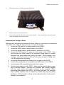
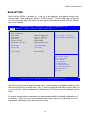
LC8810 RETAIL HARDENED COMPUTER USER MANUAL LC8810 User Manual V1.0 NOTICE The manufacturer of the Industrial Computer makes no representations or warranties, either expressed or implied, by or with respect to anything in this manual, and shall not be liable for any implied warranties of fitness for a particular purpose or for any indirect, special or consequential damages. Information in this document is subject to change without notice and does not represent a commitment on the part of the manufacturer. FCC NOTICE This device complies with Part 15 of FCC Rules. Operations are subject to the following two conditions: (1) this device may not cause harmful interference, and (2) this device must accept any interference received, including interference that may cause undesired operation. BEMATECH, International Division 999 S. Oyster Bay Rd Building #104 Bethpage, NY 11714 TEL: (516) 248-0400 FAX: (516) 248-0443 Email: [email protected] www.bematechus.com LC8810 User Manual V1.0 TABLE OF CONTENTS OVERVIEW ................................................................................................................................................ 1 CARE AND HANDLING ............................................................................................................................... 2 PRODUCT FEATURES ................................................................................................................................. 3 INSTALLATION INSTRUCTIONS ................................................................................................................... 5 SAFETY TIPS .................................................................................................................................................... 5 COMPONENT PLACEMENT.............................................................................................................................. 7 MOUNTING INSTRUCTIONS .......................................................................................................................... 7 1. TOOLS/MATERIALS REQUIRED ........................................................................................................ 7 2. PARTS ................................................................................................................................................... 7 3. DEVICE LOCATION ............................................................................................................................. 8 4. ELECTRICAL & INSTALLATION REQUIREMENTS ........................................................................... 8 5. MOUNTING THE DEVICE.................................................................................................................... 9 BIOS SETTING .......................................................................................................................................... 15 TROUBLESHOOTING................................................................................................................................ 17 SPECIFICATIONS ...................................................................................................................................... 19 LC8810 User Manual V1.0 OVERVIEW The Bematech LC8810 provides unparalleled reliability by being a fanless unit with no moving mechanical parts. It is an ideal computer for use in harsh environments with high levels of dust or oil when fan noise is not desirable. For mass storage, solid state disk provides true no-moving-part operation. In addition, all components and connectors reside on one PC board, thus no internal cables (sources of common loose connections) are required. The computer is housed in a rugged die cast case for extra protection. The LC8810 has a very compact form factor - only 2.44”H x 8.15”W x 6.93”L. Standard 75mm and 100mm VESA mounting screw holes at the bottom of case enable these units to be mounted almost anywhere – on a wall, ceiling, table top or under a counter. The LC8810 uses quad-core Intel Baytrail processors, so it can run Windows and Linux-based applications. Whether your application runs on Windows 8, Windows 7, Windows Embedded PosReady 7, or Linux*, your operating system needs are supported by the LC8810. This enables the unit to be used in a wide variety of applications – in a restaurant’s kitchen system, in a POS workstation, in an auto ID workstation, etc. The LC8810 also provides a very impressive compliment of up-to-date I/O ports – Ethernet, parallel, PS/2 and multiple USB, RS232, SVGA, DisplayPort and DVI ports are all included. 1 LC8810 User Manual V1.0 *Ask our Technical Support Team for more details on supported distributions. CARE AND HANDLING The following tips will help keep your LC8810 functioning at the optimal level: Remember to unplug the display unit from the power outlet before cleaning. Do not use alcohol (methyl, ethyl or isopropyl) or any strong dissolvent. Do not use thinner or benzene, abrasive cleaners or compressed air. To clean the LC8810 unit cabinet, use a cloth lightly dampened with a mild detergent. Do not immerse unit in water. Put the cleaner on the rag and wipe the LC8810. Never apply the cleaner directly on theLC8810. Avoid getting liquids inside the LC8810. If liquid does get inside, have a qualified service technician check it before you power it on again. Unplug this product from the wall outlet before cleaning. Do not use liquid cleaners or aerosol cleaners. Use a damp cloth for cleaning. We recommend all servicing done on this product be done by qualified service personnel. Aside from upgrades or swapping out the SSD or hard-drive please refer all other servicing to the Bematech RMA Dept. 2 LC8810 User Manual V1.0 PRODUCT FEATURES o Fanless and ventless operation o Intel Baytrail-D J1900 2GHz quad core processor, 2MB L2 Cache o Mass storage: SATA/mSATA SSD (no moving parts) or/and SATA hard disk drive o Enclosed in rugged die cast case o up to 8GB DDR3L SODIMM RAM o When mSATA SSD drives are used there are no internal connecting cables with all components mounted on single PC board for high reliability o Easy access hard disk door facilitates change of hard disk in the field o Large number of available I/O ports: 5x USB 2.0, 1x USB 3.0, 3x serial, 1x parallel, 1x VGA, 1x DVI-I, 1x DisplayPort, 1x Ethernet, 1x PS/2 keyboard and mouse, front & back speaker out and microphone in o Multimedia: Video with 1920 x 1080 max resolution with 24-bit color, ALC886/ALC892 Audio CODEC and built-in 2W audio amplifier o System boot from hard-drive, network, or USB o Universal input (100 to 240VAC, 47 to 63Hz) switching power supply o Ultra compact die cast housing – only 2.44”H x 8.15”W x 6.93”D o 75mm and 100mm standard VESA mount screw holes o Custom configurations available 3 LC8810 User Manual V1.0 4 LC8810 User Manual V1.0 INSTALLATION INSTRUCTIONS SAFETY TIPS Read these instructions carefully. Save these instructions for future reference. Install this unit only in the manner intended by the manufacturer. If you have questions, contact the manufacturer Installation measures must be taken to prevent physical damage to the power supply cord, including proper routing of the power supply cord and provision of a receptacle (socket outlet) near the fixed ITE, or positioning the fixed ITE near a receptacle (socket outlet). Installation work and electrical wiring must be done by qualified person(s) in accordance with all applicable codes & standards, including fire-rated construction. Don't attach power supply cable to the building surface or through walls, ceilings, floors and similar openings. Do not allow anything to rest on the power cord. Do not locate this product where persons will walk on the cord. When cutting or drilling into wall or ceiling, do not damage electrical wiring and other hidden utilities. Install the system away from sun rays, vapor, gases, smoke, humidity and suspended particles. Allow at least 6 inches of space from the top of the unit and 3 inches from the sides to allow proper ventilation. (This will be explained in the mounting instructions) If any problem occurs, do not try to repair the equipment by yourself, nor allow any unauthorized person to fix. Contact the manufacture for assistance. 5 LC8810 User Manual V1.0 As a safety measure, it is advised the use of a voltage stabilizer or UPS between the equipment and the line socket. This product should be operated from the type of power indicated on the power adaptor. If you are not sure of the type of power available, consult your dealer or local power company. The feeding line should be exclusive for the equipment, unless it is used for other compatible equipment and it should not overpass the maximum consumption of the line. Photocopy machines, electrical motors and any other high consumption equipment should be installed isolated from this equipment. If an extension cord is used with this product, make sure that the total ampere rating of the equipment plugged into the extension cord does not exceed the extension cord ampere rating. Also, make sure that the total rating of all products plugged into the wall outlet does not exceed the fuse rating. Unplug this product from the wall outlet and refer servicing to qualified service personnel under the following conditions: 1. 2. 3. 4. 5. 6. If If If If If If the power cord or plug is damaged or frayed liquid has been spilled into the product the product has been exposed to rain or water the product does not operate properly when the operating instructions are followed the product has been dropped or the cabinet has been damaged the product exhibits a distinct change in performance, indicating a need for service There is risk of electrical shock, even with the wire disconnected from the electrical network. Contact the Manufacture Service centers whenever necessary. Don’t try to replace the lithium battery cell under any circumstances. There is risk of explosion if an incorrect type of lithium battery cell used. Dispose of used batteries according to the instructions. 6 LC8810 User Manual V1.0 COMPONENT PLACEMENT The following is recommended when you plan the LC8810 setup: Place the LC8810 so that: 1. The RESET button is accessible. 2. The beeps from the speakers can be heard. 3. The LED indicator on the front panel can be seen. Place the LC8810 above grill/counter level, out of the way of possible spills. Leave enough spaces around the unit for ventilation. MOUNTING INSTRUCTIONS 1. TOOLS/MATERIALS REQUIRED Wood screws (4 pieces - 1/8" x 1" 1/2) Concrete wall anchors (2 pieces - 1/16" x 3/8") VESA mounting bracket or arm Measuring tape Electric drill with 5/16” and 3/8” Bits Phillips Screw driver Stud finder 2. PARTS Parts included with the product package: 1. 2. 3. 4. LC8810 unit AC – DC power adaptor Power cord Vertical mounting stand Picture 1 7 LC8810 User Manual V1.0 3. DEVICE LOCATION The location of installation should meet the following conditions: 4. Have enough space for its operation and preventive and corrective maintenance. Advisably, the floor should not be wooden, in order to avoid electrostatic shocks on the equipment. Install the equipment in a stable place, with no vibrations. Do not install the equipment on a mobile table (with wheels). The video monitor should be place strategically so that the lights of the room do not reflect the operator, disturbing the correct visibility of the screen. ELECTRICAL & INSTALLATION REQUIREMENTS Electrical requirements It is the customer’s responsibility to observe all governing codes and ordinances, and assure that the electrical installation is adequate and in conformance with National Electrical Code: ANSI/NFPA 70 — latest edition*, or CSA Standards C22.1-94, Canadian Electrical Code, Part 1 and C22.2 No.0-M91 - latest edition** and all local codes and ordinances. Have an electrical network with a ground connection, with a three pin plug (2 poles and the ground) in order to be compatible with the cable of the equipment. Check that the voltage selector is in the position corresponding to the electrical provision. Electrical network power supply: 100–240 VAC~1.5A, 50/60 Hz Before mounting the device, please make sure that: Mounting brackets (optional accessory) are available to facilitate mounting the LC8810 to a wall. 8 LC8810 User Manual V1.0 Vertical mounting stand is used for mounting the LC8810 vertically on the counter top. The installer should insure that the wall anchors used with the mounting brackets have the capacity to support 6.5 kg (14.5 lb.). This weight is determined by adding a safety margin weight to the weight of the unit. Wall anchors with specified weight capacity are available commercially. The power outlet socket is located near to the desired mounting location for the LC8810. 5. MOUNTING THE DEVICE Mount the LC8810 vertically on with provided stand Allow at least 3 inches of space from the top of the unit and 6 inches from the sides to allow proper ventilation. See the picture below: Picture 2 1. Loosen the two thumb screws on the HDD cover on the side of the unit and remove the HDD cover. Picture 3 9 LC8810 User Manual V1.0 2. mount the LC8810 on the vertical stand and secure with two M3 screws from bottom of the bracket. Picture 4 Mount the LC8810 horizontally above counter Allow at least 6 inches of space from the top of the unit and 3 inches from the sides to allow proper ventilation. See the picture below: Picture 5 10 LC8810 User Manual V1.0 Mounting the LC8810 to the wall with the VESA mounting brackets Allow at least 3 inches of space from the top of the unit and 6 inches from the sides to allow proper ventilation. See the picture below: Picture 6 The LC8810 is a fanless and ventless unit. Heat is dissipated through the metal case. So, allow at least 6 inches of space from the top of the unit and 3 inches from the sides for proper ventilation. It’s recommended to mount the unit vertically to maximize ventilation effect. Vertical mounting stands are available from Bematech. 11 LC8810 User Manual V1.0 Replacing Hard Disk Drive Replacing hard disk drive (or SSD) on LC8810 is a very easy task. No tools are required to perform this action. Before starting the replacement process, power down your LC8810 and disconnect it from the wall outlet. Wearing an anti-static wristband is preferable whenever working with sensitive electrical equipment. 1. Unscrew two thumbscrews located at the side of the unit. 2. Slide out the Hard Disk metal cover. 3. Slide the HDD tray button to the left and lever will be released. 12 LC8810 User Manual V1.0 3. Pull out the lever to extract the hard disk drive. 4. Gently remove the hard disk drive. 5. Insert new hard disk and close level to lock position. Then reinstall the hard disk metal cover and tighten the thumb screws. Connections and Turning on Power Make sure that all systems are powered off before making or removing any connections to the LC8810 unit. Follow the steps below in connecting the devices: 1. Connect the VGA cable of the display monitor to the LC8810. 2. Connect the RS232 cables of serial devices to the LC8810. 3. Connect the parallel cable of parallel device to parallel port of LC8810. 4. Connect the PS/2 keyboard (or bump bar) and mouse to the LC8810. Note that the bump bar cable connector has connector locking feature to prevent connector from being pulled out by pulling the cable. When plugging in the connector, grab the connector at the end of the plug and push in tightly until it is fully snapped into the socket. 5. Connect the Ethernet cable from Ethernet hub or switch to the LC8810. 6. Connect other peripherals such as speakers and USB devices to the LC8810. 7. Connect power to all peripheral devices and turn on power. 8. Connect power adapter to the LC8810. Make sure that the flat side of power plug is oriented upwards. Reversing the orientation and forcefully plugging into the power socket will result in damage to the connector. (When unplugging power adapter from LC8810, do not pull the cable. The connector has a locking function that is released by holding the plug and pulling backwards. If the connector is forced out by pulling the cable, it may result in damage to the connector.) 13 LC8810 User Manual V1.0 9. Connect power cord to the power adapter and plug the power cord into AC power outlet. (The power adapter must be connected to the LC8810 f i r s t before it is connected to AC power outlet. Do not connect AC power before connecting to LC8810). 10. By default, the unit is set to turn on power automatically when power is connected. If it does not power up, press the on/off switch on the front panel to turn on power and check for correct CMOS configuration settings. 11. If the LC8810 had been shutdown from the operating system, it may be restarted by pressing the power on/off switch on the front panel of the LC8810. To turn off power to the unit, press and hold the power on/off switch for 5 seconds. 14 LC8810 User Manual V1.0 BIOS SETTING Each time the LC8810 is powered on, it will run a self diagnostic and continue booting from storage media. BIOS settings are stored in a CMOS memory. To enter BIOS setup, as soon as you hear the system beep, just before LCI logo splash screen appears, quickly press the [Delete] key on the keyboard. Aptio Setup Utility - Copyright (C) 2013 American Megatrends, Inc. Main Advanced Chipset Security Boot Save & Exit BIOS Information BIOS Vendor Core Version Compliancy Project Version Build Date and Time American Megatrends 5.0.0.9 0.09 x64 UEFI 2.3; PI 1.2 DMS BT12X006 04/08/2014 09:24:38 System Date System Time [Wed 05/07/2014] [17:11:06] Access Level Administrator Set the Date. Use Tab to Switch between Date elements. : Select Screen : Select Item Enter: Select +/- Change Opt. F1: General Help F2: Previous Values F9: Optimized Defaults F10: Save & Exit ESC: Exit Version 2.16.1242. Copyright (C) 2013 American Megatrends, Inc. Use left and right arrows to select the setup menu. Use arrow keys to navigate to different menu items and press [Enter] to select menu. Use -/+ keys to change the field value or press [Enter] to go to sub screen. When configuration is finished, press [F10] key to save the settings and exit setup. In most of the applications, parameters are detected automatically the default configuration will be suitable. There are only a few parameters that might need to be customized for some applications. Examples of such cases are shown below: 15 LC8810 User Manual V1.0 Boot Device Priority Sequence To specify the boot sequence from available devices, enter the [Boot] menu. Then setup [Boot Option Priorities] to choose the priority desired for the booting process from the list of available boot devices. I/O Configuration: Serial and Parallel Ports To configure the serial ports, go to [Advanced] menu. Select [Super IO Configuration] and then you will be able to choose / change the address and IRQ for all the ports. For each serial ports, option is available to select power function on pin 9 of the port: Disabled +5V +12V Video Configuration The DVI-I video connector provides both analog VGA and Digital video output. For connection to VGA displays, a DVI-to-VGA converter or DVI-to-VGA cable can be used. To select between analog VGA video output and digital video output, select [Advanced] menu, then select [Display Settings]. Network boot If you desire to enable your system to boot from a network, go to [Advanced] menu. Then setup [Network] option to select "UEFI only" or "Legacy only". Save the settings and reboot into BIOS, the network boot options will then be available [Boot] menu. Restore to Optimized Defaults If the BIOS settings are accidently changed and it’s necessary to restore setting to the optimized default values, select menu [Save & Exit] and then [Restore Defaults]. Select [Yes] in the confirmation dialog box. Then select [Save Changes and Exit] (or press [F10]) to save the changes. 16 LC8810 User Manual V1.0 TROUBLESHOOTING There are no user serviceable components inside the LC8810. Service should be performed only by Bematech or qualified personnel certified by Bematech. The following guide lines will help in identifying the source of a problem: Video monitor display is blank 1. If the power LED on the monitor is off, check that the monitor is properly connected to its power supply and the power supply is properly plugged into a functioning AC outlet. 2. Adjust the contrast controls on the monitor display. 3. Check that the video cable is plugged in properly on both the monitor and the LC8810. 4. If the power LED on LC8810 is off, check that the LC8810 is properly connected to its power supply adapter and the power adapter is properly plugged into a functioning AC outlet. 5. If the LC8810 is connected to a power supply but the power LED is off, press the power button to turn on the unit. If it does not turn on, try replacing the power supply. 6. Replace the LC8810 if necessary. Video monitor display is blue or frozen 1. Reset the LC8810 and check the system information on the screen during boot up. 2. If unit reboots correctly, try running application again. If same problem occurs, try reinstalling the application software. 3. If unit cannot reboot correctly, try replacing the hard disk drive (or SSD). Station is not communicating with server Application 1. Check that the LC8810 s' IP addresses are correct and unique (no conflict) and the port number matches application software setup. 2. Check the Ethernet cable connections at the problem LC8810 s and at the Ethernet hub or switch. 3. Check that host server IP address matches the LC8810 IP address group. Try pinging one of the LC8810 IP address from the host. 4. Check host server application software setup. Restart software if necessary and test again. 5. Reboot the host server and test again. 6. Replace Ethernet hub or switch and test again. LC8810 does not respond to keyboard commands 1. Check the keyboard cable connections at both the keyboard and the LC8810. Unplug the cable and re-insert fully. Check whether it snaps in correctly. Note that it’s necessary to hold the back end of the PS2 connector near the cable exit and push in hard to get the locking connector into place. 2. Test with known good keyboard and cable. If it works, replace the cable and/or keyboard. 17 LC8810 User Manual V1.0 Attached RS232 device is not working 1. Check that the device and LC8810 have power. 2. Check RS232 connections at the device and LC8810. 3. Check whether baud rate and data format settings of application is matching with the device. 4. Attach the wrap plug to the device end of the RS232 cable and run an RS232 port test program. If the test passes, replace the serial device. If the test fails, go to step 5. 5. Attach a wrap plug to the RS232 port of the LC8810 and rerun the RS232 loop test. If the test passes, replace the RS232 cable. If the test fails, replace the LC8810. LC8810 does not boot from internal mSATA SSD 1. Check in BIOS setting whether the boot device priority is set to boot from mSATA (note that the mSATA SSD is installed as SATA hard disk drive). 2. Check if the operating system on the mSATA SSD is corrupted. If so, try reinstalling the operating system or replace the mSATA SSD. 18 LC8810 User Manual V1.0 SPECIFICATIONS I/O PORTS SYSTEM SYSTEM CPU Video CPU Intel Baytrail-D J1900 2GHz Quad Core processor with 2MB L2 Cache System Memory Up to 8GB, DDR3L SODIMM x1 Mass Storage Internal SATA HDD, SATA SSD, or mSATA SSD 1920x1080 pixels max2GHz Intel Baytrail-D J1900 VGA, Core DVI-Iprocessor and DisplayPort Quad with 2MB L2 Cache 10/100/1000 Mbits Ethernet Network boot capable Up to 8GB, DDR3L SODIMM x1 Video PS/2 mini-DIN6 connectors Internal SATA HDD, SATA SSD, or mSATA SSD USB 2.0 ports x6, USB 3.0 port x1 Keyb Serial Port DB9 x3 (COM1 to COM3) Optional +5V/+12V power at pin 9 Seria Parallel Port POWER SUPPLY DB25 x1 (LPT1) Paral Mic in x2 and Speaker out x2 with 12VDC 2W power amplifier 100 to 240VAC, 1.5A max Mini PCIe socket (support WiFi 50/60Hz card) 12VDC 5A Audio Network Interface System Memory Keyboard/Mouse Mass Storage USB Ports POWER SUPPLY Single power input 12VDC Audio Single power input Power adapter input 100 to 240VAC, 1.5A max 50/60Hz Power adapter input Expansion Slot Power adapter output 12VDC 5A Power adapter output ENVIRONMENT MECHANICAL Operating temperature Relative humidity Weight MECHANICAL Weight 4.9 lbs Dimension (WxDxH) 8.15" x 6.93" x 2.44" Storage temperature Dimension (WxDxH) Relative humidity (207mm x 176mm x 62mm) Housing Die cast Housing Video CPU Intel Baytrail-D J1900 2GHz Quad Core processor with 2MB L2 Cache System Memory Up to 8GB, DDR3L SODIMM x1 Mass Storage Internal SATA HDD, SATA SSD, or mSATA SSD USB Expa 0°C to 40°C 5% lbs to 90%, non-condensing 4.9 Oper Rel 0°C tox 60°C 8.15" 6.93" x 2.44" 5% to 80%, non-condensing (207mm x 176mm x 62mm) Stora Rel Die cast I/O Video System Memory Keyboard/Mouse Mass Storage USB Ports 1920x1080 pixels max Intel Baytrail-D J1900 2GHz VGA, DVI-I and DisplayPort Quad Core processor with 2MB L2 Cache 10/100/1000 Mbits Ethernet Network boot capable Up to 8GB, DDR3L SODIMM x1 PS/2 mini-DIN6 connectors Internal SATA HDD, SATA SSD, or mSATA SSD x6, USB 3.0 port x1 USB 2.0 ports Serial Port DB9 x3 (COM1 to COM3) Seria Network Interface 19 Netw ENVI I/O PORTS SYSTEM SYSTEM CPU I/O Netw Keyb USB