1
CLEMENTS
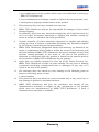
HiFlo
High Vacuum High Flow
Suction Pump
SUC 84112
User Manual
Manual No. SUC 91005 415
Issue 23
CLEMENTS
Safety
Thank you for purchasing this Clements HiFlo High
Suction Pump.
For your safety it is imperative that this unit only be
operated by authorised personnel in accordance with the
instructions as described in this manual. Operated in
this way, the HiFlo High Suction Pump will provide the
standard of service specified.
Due to continual improvements in product design, the
HiFlo High Suction Pump may vary in detail from the
descriptions in this manual. In the event of further
questions please contact your local distributor or BMDi
TUTA Healthcare direct.
User Manual
HiFlo High Suction Pump
Manual Number SUC 91005 415 Issue 23
Copyright © 2009 BMDi TUTA Healthcare Pty Ltd
The information in this manual was originated by, and is the exclusive
property of BMDi TUTA Healthcare Pty Ltd. It is furnished for customer
information only, and is not an authorisation or licence to make this
product or to furnish this information to others.
BMDi TUTA Healthcare Pty Ltd
Unit 4B, 128-130 Francs Street
Lidcombe NSW 2141 Australia
Phone:
+61 2 9466 5300
Website: www.medaust.com
2
CLEMENTS
Contents
Classifications .................................................
4
Specifications ..................................................
5
Transportation and Storage ............................
6
Description ......................................................
8
Installation and Operation ..............................
9
Spares ..............................................................
13
Maintenance ....................................................
15
Troubleshooting ..............................................
17
Diagnostic Setup .............................................
19
Disassembly and Repair ..................................
21
Warranty ..........................................................
26
Contents
3
CLEMENTS
Identification
SUC 84112 HiFlo High Vacuum / High Flow Suction Pump
Intended Use
To provide a continuous vacuum source, within the stated
operating vacuum range, for the aspiration of fluids and
particulate matter in medical procedures carried out by
clinically trained and authorized personnel.
Uninterrupted Availability
This equipment is mains powered. If patient care requires
the uninterrupted availability of a source of vacuum, the
clinical facility must make provision for either a backup
power supply or standby suction units which are battery
or manually powered.
Classifications
GMDNS Code
36777
GMDNS Term
Suction unit, electric powered
GMDNS Synonym
Aspirator
Device Class
Class IIa
Electric Shock
Protection
Class I Equipment
Additional Electric
Shock Protection
Defibrillation-proof Type BF Applied Part
Sterilisation
Not supplied in sterile state
Anaesthetic
Rating
NOT Category AP
NOT Category APG
Operation Mode
Continuous operation
4
Classifications
CLEMENTS
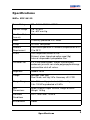
Specifications
HiFlo SUC 84112
Power Rating
220 - 240 V 50/60 Hz 380W
Vacuum Range
0 to –93 kPa
0 to –697 mm Hg
Max Flow Rate
(free air)
55 litre / min
Motor
Thermally protected PSC motor
Pump
Oil Less twin piston
Ambient
Requirement
Continuous operation in ambient temperatures of 5°
C to 35°C.
Filters
Inlet: disposable bacteria filter
Exhaust: clean, bleached cotton wool (5g)
Internal: disposable hydrophobic filter
Collection Jar
2 x 2 litre autoclavable, shatter resistant polycarbonate jars with non-static polypropylene bungs
and overflow shut-off valves.
Regulator
Needle Valve
Gauge
Bourdon tube type
Dual Scale, mm Hg / kPa. Accuracy ±3% FSD
Gauge Range
0 to -760 mm Hg graduated at 20 mm Hg
0 to -100 kPa graduated at 5 kPa
Unit
Dimensions
Width 406mm, Depth 305mm, Height 800mm
Weight 16.5kg
Standard
Conditions
25°C, Sea Level, 100kPa
Environment
Indoor
Specifications
5
CLEMENTS
Transportation and Storage
Environmental conditions for transportation and storage are
shown in the following table. In addition, for vehicular
transportation, the unit should be packed in its original
packaging and kept upright.
Parameter
Minimum
Maximum
Temperature
10ºC
40ºC
Humidity
60% RH
95% RH
Barometric Pressure 700 mBar
1060 mBar
Warning Symbols Legend
The warning symbols marked on the equipment and their
meanings are shown as follows.
Attention, consult accompanying documents
Defibrillation-Proof Type BF applied part
Dispose of product according to
requirements of WEEE directive
6
Transportation and Storage
CLEMENTS
Electromagnetic Interference
This equipment generates, uses and can radiate radio frequency
energy and, if not installed and used in accordance with the
instructions, may cause harmful interference to radio
communications. However, there is no guarantee that
interference will not occur in a particular installation. If this
equipment does cause harmful interference to radio or television
reception, which can be determined by turning the equipment
off and on, the user is encouraged to try to correct the
interference by one or more of the following measures:
•
Reorient or relocate the receiving antenna.
•
Increase the separation between the equipment and the
receiver.
•
Connect the equipment into an outlet on a circuit different
from that to which the receiver is connected.
•
Consult the dealer or an experienced radio/TV technician
for his or her help.
Changes or modifications to the equipment not expressly
approved by Clements could void the user’s authority to operate
the equipment.
Electromagnetic Interference
7
CLEMENTS
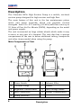
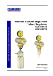
Description
The Clements HiFlo High Suction Pump is a mobile, enclosed
suction pump designed for high suction and high flow.
The main feature of this unit is the low maintenance piston
motor and pump assembly which can generate suction
strengths from 0 to -675 mm Hg (-90 kPa) with flow rates up to
55 litres of Free Air Per Minute (FAPM), depending on the model
and power supply.
The unit is mounted on large rubber wheels which make it easy
to move to any part of a hospital. The unit also has a storage
compartment at the rear to house additional tubing, handpieces
and other items needed when using the pump.
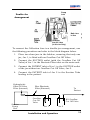
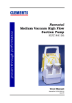
Main Components of Unit
8
1
Power Switch
6
Exhaust Filter
2
Vacuum Gauge
7
Handle
3
Regulator Control Knob
8
Tube Storage Hooks
4
Inlet Connection
9
Storage Compartment
5
Pump (Internal)
Description
CLEMENTS
Installation and Operation
Installation
The Clements HiFlo High Suction Pump is supplied with:
• 2 x 2 litre Collection Jar with Bung Assembly
• 1 x 2.4 metre length of Suction Tubing
• 1 x 0.4 metre length of Suction Tubing
Important
Remove strapping from motor before starting. Ensure power is
disconnected before opening unit.
WARNING
This unit can generate high vacuums. It must not be
used for applications which require low vacuum.
Always check patient requirements before applying
the Clements HiFlo High Suction Pump.
For applications which require low vacuum, please contact your
distributor for information about the Clements Low Suction
range of products.
Connecting The Collection Jars
Because the unit is fitted with two Collection Jars it can either
be connected in a single-jar arrangement or a double-jar
arrangement.
With the single-jar arrangement, only one jar is in use at a time,
with the second jar on standby. As one jar is filled it is
disconnected, so that it can be emptied, and the other jar is
connected.
The double-jar arrangement allows both jars to be in use at the
same time, thus providing longer periods between changeover.
Installation and Operation
9
CLEMENTS
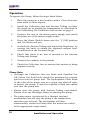
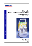
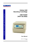
Single-Jar Arrangement
To connect the Collection Jars in a single-jar arrangement, use
the following procedure and refer to the block diagram below.
1.
Place two clean jars in the holders, ensuring that both jars
are fitted with an Overflow Cut Off Valve.
2.
Connect the SUCTION outlet of the jar to be used first to
the Bacteria Filter inlet on the main unit.
3.
Connect the PATIENT inlet of the jar to be used first to the
Suction Tube leading to the patient.
4.
When the first jar is full, disconnect it and use steps 2 and
3 to connect the second jar.
Hydrophobic
Shut Off Valve
Filter (Internal)
V
Suction
Pump
Unit
10
To
Patient
Blue Bacteria
Filter (External)
Overflow Cut
Off Valves in
BOTH Jars
Jar in
Use
Installation and Operation
V
Jar on
Standby
CLEMENTS
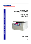
Pump
Inlet
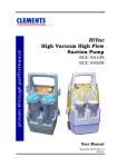
Double-Jar
Arrangement
Both Jars
In Use
Overflow
Cut Off Valve
(in this Jar Only)
To connect the Collection Jars in a double-jar arrangement, use
the following procedure and refer to the block diagram below.
1.
Place two clean jars in the holders, ensuring that only one
jar, Jar 1, is fitted with an Overflow Cut Off Valve.
2.
Connect the SUCTION outlet (with the Overflow Cut Off
Valve) of Jar 1 to the Bacteria Filter inlet on the main unit.
3.
Connect the PATIENT inlet of Jar 1 to the SUCTION outlet
of the jar without an Overflow Cut Off Valve, Jar 2.
4.
Connect the PATIENT inlet of Jar 2 to the Suction Tube
leading to the patient.
Hydrophobic
Shut Off Valve
Filter (Internal)
Blue Bacteria
Filter (External)
Overflow
Cut Off
Valve
Suction
Pump
Unit
To
Patient
NO Overflow
Cut Off Valve
V
Jar 1
Installation and Operation
Jar 2
11
CLEMENTS
Operation
To operate the Pump, follow the steps listed below.
1.
Place the pump on a level surface with a 15cm clearance
from walls or other objects.
2.
Install the Collection Jars and Suction Tubing in either
the single-jar or double-jar arrangement as described in
the Connecting The Collection Jars section on page 8.
3.
Connect the unit to the mains power supply and switch
the power on at the mains supply outlet.
4.
Press the Power Switch down into the ‘|’ (ON) position
and the Motor will run.
5.
Occlude the Suction Tubing and adjust the Regulator, by
turning the knob, to obtain the required vacuum level,
as indicated on the Vacuum Gauge.
6.
Check that there is no loss of vacuum in the Suction
Tubing and fittings.
7.
Connect the catheter to the patient.
8.
Check the Collection Jars to ensure that suction is being
applied correctly.
Please Note:
• Although the Collection Jars are fitted with Overflow Cut
Off Valves, the fluid levels should be monitored to prevent
spill-over into the pump unit. The Hydrophobic Filter fitted
to the inlet of the pump acts as a single use shut-off valve
to protect the pump. It must be replaced if fluid has spilled
over into the pump unit.
• Always start the pump with Suction Tubing unoccluded.
Always clear any blockages before re-starting the pump.
• The pump motor is protected by a thermal overload
mechanism that will stop the pump if the temperature
exceeds a pre-set level. The mechanism will then
automatically restart the Pump after the motor has cooled
to the appropriate temperature.
12
Installation and Operation
CLEMENTS
If the motor thermal overload trips, switch the power off at
the mains switch. This will prevent unexpected re-starting of
the pump when the thermal overload automatically resets
upon cooling.
• If it is suspected that fluid may have entered the pump,
either by an external spill or by a jar overflow, the unit must
be taken out of service until the fault has been fixed and its
continued electrical safety has been confirmed. The service
department must also be notified of any potential biohazard.
Spares
MUL 94003 702
Fuse T5.0 Amp 250V
MUL 94004 000
Mains Power Switch Green Rocker
SUC 80297 001
Kit Yellow Suction Tubing (20 Metre roll)
SUC 80301
2 litre Collection Jar for Suction Pumps
SUC 80404 001
Single Use Plastic Handpiece (pack of 10)
SUC 84100 162
Blue Bacteria Filter (Set of 12)
SUC 84200 033
Bung Assembly with Overflow Cut Off Valve for 2
litre Collection Jar
SUC 91005 415
User Manual for the HiFlo High Suction Pump
Spares
13
CLEMENTS
Spares
SUC 37043
Cotton Wool for Suction Pumps Exhaust Filter
(Pack of 10, 5 grams each)
SUC 80330
High Vacuum Gauge 0-100kPa
SUC 84100 049
Exhaust Filter Assembly for Suction Pumps
SUC 84100121
Resilient Motor Mount (Pack of 4)
SUC 84100 400
Hydrophobic Shut-Off Valve Filter
SUC 84100 505
Footswitch Kit for Suction Pumps with (Switch,
Pneumatic Actuator)
SUC 84109 002
Motor and Pump for Hi Vac/Hi Flo
SUC 84200 501
Seal for Collection Jar Bung (Set of 2)
SUC 84200 502
Suction Inlet Nipple for 2 litre Jar Bung
(Set of 4)
SUC 84200 503
Kit Grey Bung Float Chamber (Set of 2)
SUC 84200 518
Washer for Overflow Valve (Pack of 4)
SUC 84200 519
Blue Male Nipple for Bacteria Filter
(Pack of 10)
SUC 84200 520
Blue Female Nipple for Bacteria Filter
(Pack of 10)
SUC 89107
Kit for Pump Vacuum Controller
(Needle Valve Type)
SUC 89240 069
Regulator Knob Replacement Kit for Suction Pumps
(Regulator Knob, Screw)
14
Spares
CLEMENTS
Maintenance
IMPORTANT
There are no user-serviceable components inside.
Maintenance must be carried out by qualified
personnel only.
To keep your Clements HiFlo High Suction Pump in good condition,
the following maintenance is recommended.
After Each Operation
• Blue Bacterial Filter
The blue bacterial filter is an important device to help protect the
pump from moisture and bacteria taken from patient airways.
Clements recommend that the filter be changed every month or
when the unit is used on infectious patients or when damp or
discoloured.
• Housing
Wipe clean with a damp soapy cloth. Do not immerse or allow
liquid to enter the housing.
• Suction Tubing
Suction Tubing should be sterilised with sterilants determined
by local protocols and compatible with PVC tubing. Suction
Tubing may be autoclaved to a maximum of 121°C for 20
minutes. At higher temperatures the Suction Tubing will
discolour and lose shape.
• Collection Jars
Place jars upright or up-side-down in autoclave: not on their
sides. Autoclave to a maximum of 136°C for 10 minutes. Do not
use phenolic solutions as disinfecting agents in polycarbonate
jars.
• Bung
Disconnect float cage and float from Bung. Place all items
upright or up-side-down in autoclave: not on their sides.
Autoclave all items to a maximum of 136°C for 10 minutes.
Note: Do not use abrasive cleaning agents as this may damage
plastic surfaces and reduce the expected performance of an item.
Maintenance
15
CLEMENTS
After Every 100 Hours or 2 Months of Operation
• Replace the Exhaust Filter:
1. Remove the Exhaust Filter from the rear of the unit.
2. Unscrew the caps and replace the cotton wool. The filter
takes 5 gram of bleached and teased-out cotton wool.
• Check all Suction Tubing and replace if it is perished, soft
or discoloured. Also check the tubing nipples.
• Check the seal rings on the Bungs and replace them if they
are hard, cracked or perished. Check the fit of the Bung in
the Collection Jar.
• Check the Overflow Cut Off Valve seals and replace them if
they are perished or damaged.
IMPORTANT
The preceding maintenance should also be carried out
immediately after use with infectious patients.
Disposal and Recycling
Waste Materials
The contents of the collection jars, suction tubing, bacteria filter, internal hydrophobic shut-off filter, or the cotton wool in the
exhaust filter may contain biohazard wastes. Handle using safe
handling procedures, which may include the use of rubber
gloves and eye protection, and dispose of according to local protocols for biohazard materials.
Recycling
At the end of their service life, the pump and accessories should
be dismantled if necessary, and disposed of according to the
WEEE directive.
16
Maintenance
CLEMENTS
Troubleshooting
Fault
Check
Rectify
No Suction But
Tubing Blocked
Clear or Replace
Motor is Working
Overflow Cut Off Valve Clear, Replace or
Closed
Empty Jar
Hydrophobic Shut –Off Replace
HyValve Filter
drophobic Shut-Off
Valve Filter
Blocked
Inlet Blocked
Vacuum Gauge
fective
Clear
De-
Replace Vacuum
Gauge
Regulator Blocked
Clear or Replace
Bung Not Sealing
Adjust or Fit New Seal
Regulator at Zero
Adjust Setting
No Suction:
Mains Fuse Blown
Replace
Motor Not Working
Faulty Mains Power
Lead
Replace
Power Not Turned On
Turn On
Unit Fuses Blown
Replace
Thermal Overload Acti- Wait For Unit To Cool
vated
Down
No Suction But
Humming Can Be
Heard From Motor
Blockage In Pump
Dismantle And Clean
Pump
Motor Windings
Replace Motor
Troubleshooting
17
CLEMENTS
Fault
Check
Rectify
Not Enough Suction
Regulator Setting Too Adjust To Correct SetLow
ting
Leaks In Tubing or
Fittings
Tighten Connections
Blockage In Tubing or
Fittings
Clear or Replace
Hydrophobic ShutOff
Valve Filter Blocked
Replace
Hydrophobic Shut-Off
Valve Filter
Excessive Noise
Pump Worn
Replace Pump
Coming From Pump
Pump Incorrectly Assembled
Assemble Correctly
Pump Runs
termittently
Thermal Overload Is
Cutting In and Out
Disconnect Mains
Power And Wait For
Unit To Cool Down
In-
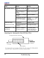
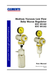
Replacing the Hydrophobic Shut Off Valve Filter
Transparent Filter Housing
To Patient
To Pump
Filter Media
To ensure there is no entry of fluid into the pump the Hydrophobic
Shut Off Valve Filter MUST be fitted as shown above.
18
Troubleshooting
CLEMENTS
Setup for Diagnostic and Performance Testing
Note that the following arrangements are not used for actual
suctioning applications. They are specified to remove
unnecessary variations when diagnosing faults and as a
standard setup for performance measurement.
Vacuum Check
Max
1. Unoccluded - zero check
Vacuum
Gauge
Disconnect all items from inlet and with pump switched off,
confirm that gauge reads zero. A non-zero reading indicates a
faulty gauge.
Set vacuum control knob to maximum, switch on pump and
confirm that gauge reads zero. A non-zero reading indicates
obstruction in internal tubing or connections.
Max
2. Occluded - vacuum check
Vacuum
Gauge
Switch on pump and occlude inlet. Note maximum vacuum
reading.
Max
3. Occluded - gauge check
Calibrated
Vacuum
Gauge
Vacuum
Gauge
Connect a calibrated vacuum gauge directly to inlet and repeat
maximum vacuum reading.
Confirm that pump gauge reads within the specified tolerance.
Diagnostic Setup
19
CLEMENTS
Flow Check
1. Occluded - leak check
Max
Jar:
SUC 81099 (1 litre)
or
SUC 80312 (2 litre)
Tubing: SUC 80297 (8x13mm)
Vacuum
Gauge
Connect pump as shown in diagram. Set vacuum control knob
to maximum, and switch on pump. Occlude jar inlet and confirm that pump achieves the same maximum vacuum as in the
previous vacuum check setup . Any difference indicates leaks in
jar or connections.
2. Unoccluded - flow check
Max
Jar:
SUC 81099 (1 litre)
or
SUC 80312 (2 litre)
Tubing: SUC 80297 (8x13mm)
Vacuum
Gauge
Calibrated
Flowmeter
Collection
Jar
Connect pump as shown in diagram. Set vacuum control knob
to maximum, and switch on pump. Connect jar inlet to
calibrated flow meter and note flow reading.
If flow is significantly below specification, check internal tubing
and pump itself (or internal shutoff valve if fitted).
20
Diagnostic Setup
CLEMENTS
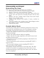
Disassembly and Repair
Dismantling The Pump
The steps for dismantling the Pump are as follows.
1. Disconnect the unit from the mains power supply.
2. Remove Collection Jars and Suction Tubing.
3. Remove the 4 screws from the base plate tabs at the rear
of the unit and push the housing forward off the base
plate.
4. Remove the four cylinder head screws from each head.
Remove the cylinder heads.
5. Check O-ring, pistons and replace if worn, cracked or
perished.
6. Clean the inside of the cylinder head. Check flapper valves
and replace if worn, cracked or perished.
7. Reassemble pump.
Periodic Safety Check
The following safety checks should be performed at least every
24 months by a qualified person who has adequate training,
knowledge, and practical experience to perform these tests.
* Inspect the equipment and accessories for mechanical and
functional damage.
* Inspect the safety relevant labels for legibility.
* Inspect the fuse to verify compliance with rated current and
breaking characteristics.
* Verify that the device functions properly as described in the
instructions for use.
* Test the protection earth resistance according IEC 60601-1:
Limit 0.2 ohm.
* Test the earth leakage current according IEC 60601-1:
Limit: NC 500 µA, SFC 1000µA.
The leakage current should never exceed the limit. The data
should be recorded in an equipment log. If the device is not
functioning properly or fails any of the above tests, the device
has to be repaired.
Disassembly and Repair
21
CLEMENTS
Fuse Replacement
The Pump is fitted with two cartridge fuses located in fuse
holders that are accessible from outside the unit. To replace the
fuses use the following procedure.
1.
Disconnect the unit from the mains power supply.
2.
Locate the two fuse holders which are mounted on the
rear side of the unit at the lower right-hand side.
3.
Lift off the fuse holder cover.
4.
Remove the old fuses and inspect them. If they are blown,
replace them with new fuses.
5.
Replace the fuse holder cover.
6.
Connect the unit to the mains power supply, switch the
power on, and ensure that the unit is operating correctly.
Electrical Wiring Diagram
22
Disassembly and Repair
CLEMENTS
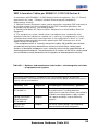
EMC Information Tables per EN60601-1-2:2001-09 Section 6.
In accordance with EN 60601-1-2:2001 Medical electrical equipment - Part 1-2: General
requirements for safety - Collateral standard: Electromagnetic compatibility Requirements and tests
1) “Medical Electrical Equipment needs special precautions regarding EMC and needs to
be installed and put into service according to the EMC information provided in the
Accompanying Documents” (the following tables).
2) “Portable and Mobile RF Communications Equipment can affect Medical Electrical
Equipment.”
3) “The equipment or system should not be used adjacent to or stacked with other
equipment and that if adjacent or stacked use is necessary, the equipment or system
should be observed to verify normal operation in the configuration in which it is used.”
The following tables provide information regarding the EMC characteristics of this
Medical Electrical Equipment.
* The compliance levels of immunity referred to in tables 202 and 204 have not been
arrived at by testing, but by declaration on the basis that the HiVac suction pump
contains no electronic components and is inherently immune to the specified levels of
electromagnetic disturbance. The performance of all functions of the HiVac suction pump
are considered essential performance for the purpose of electromagnetic immunity.
Table 201 — Guidance and manufacturer’s declaration - electromagnetic emissions
- all equipment and systems
Guidance and manufacturer’s declaration - electromagnetic emissions
The HiVac suction pump is intended for use in the electromagnetic environment
specified below. The customer or user of the HiVac suction pump should assure that it is
used in such an environment.
Emissions Test
Compliance
Electromagnetic environment - guidance
Harmonic Emissions
IEC 61000-3-2
Class A
Voltage fluctuations /
flicker emissions
IEC 61000-3-3
Complies
The HiVac suction pump is suitable for use in
all establishments, including domestic
establishments and those directly connected to
the public low-voltage power supply network
that supplies buildings used for domestic
purposes.
RF emissions
CSIPR 14-1
Complies
The HiVac suction pump is not suitable for
interconnection with other equipment.
Emissions Guidance Table 201
23
CLEMENTS
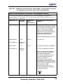
Table 202 — Guidance and manufacturer’s declaration - electromagnetic immunity
- for all equipment and systems
Guidance and manufacturer’s declaration - electromagnetic immunity
The HiVac suction pump is intended for use in the electromagnetic environment
specified below. The customer or user of the HiVac suction pump should assure that it is
used in such an environment.
Immunity Test
IEC 61000
test level
Compliance
level
(not tested) *
Electromagnetic
environment - guidance
Electrostatic
discharge (ESD)
IEC 61000-3-4
±6 kV contact
±8 kV air
±6 kV contact
±8 kV air
Floors should be wood,
concrete or ceramic tile. If
floors are covered with
synthetic material, the relative
humidity should be at least
30%.
Electrical fast
transient/burst
IEC 61000-4-4
±2 kV for power
supply lines
±1 kV for input/
output lines
±2 kV for power
supply lines
±1 kV for input/
output lines
Mains power quality should be
that of a typical commercial or
hospital environment.
Surge
IEC 61000-4-5
±1 kV line(s) to
line(s)
±2 kV line(s) to
earth
±1 kV line(s) to
line(s)
±2 kV line(s) to
earth
Mains power quality should be
that of a typical commercial or
hospital environment.
Voltage dips, short
interruptions and
voltage variations
on power supply
input lines
IEC 61000-4-11
<5 % UT
(>95% dip in UT
for 0.5 cycle)
40 % UT
(60% dip in UT
for 5 cycles)
70 % UT
(30% dip in UT
for 25 cycles)
<5 % UT
(>95% dip in UT
for 5 sec)
<5 % UT
(>95% dip in UT
for 0.5 cycle)
40 % UT
(60% dip in UT
for 5 cycles)
70 % UT
(30% dip in UT
for 25 cycles)
<5 % UT
(>95% dip in UT
for 5 sec)
Mains power quality should be
that of a typical commercial or
hospital environment. The unit
shut off during the >95% dip
for 5 sec disturbance. If the
user of the HiVac suction
pump requires continued
operation during power mains
interruptions, it is
recommended that the HiVac
suction pump be powered
from an uninterruptible power
supply or battery.
Power frequency
(50/60Hz)
magnetic field
IEC 61000-4-8
3 A/m
3 A/m
Power frequency magnetic
fields should be at levels
characteristic of a typical
location in a typical
commercial or hospital
environment.
24
Immunity Guidance Table 202
CLEMENTS
Table 204 — Guidance and manufacturer’s declaration - electromagnetic immunity
- for equipment and systems that are NOT life-supporting.
Guidance and manufacturer’s declaration - electromagnetic immunity
The HiVac suction pump is intended for use in the electromagnetic environment
specified below. The customer or user of the HiVac suction pump should assure that it is
used in such an environment.
Immunity Test
IEC 61000
test level
Compliance
level
(not tested) *
Electromagnetic environment guidance
Portable and mobile
communications equipment should
be used no closer to any part of the
HiVac suction pump, including
cables, than the recommended
separation distance calculated from
the equation applicable to the
frequency of the transmitter.
Recommended separation distance
Conducted RF
3 Vrms
IEC 61000-4-6
150 kHz to
80 MHz
Radiated RF
3 V/m
IEC 61000-4-3
80MHz to
2.5 GHz
3 Vrms
d = [3.5/V1]√P
3 V/m
d = [3.5/E1]√P 80 MHz to 800MHz
d = [7/E1]√P 800 MHz to 2.5GHz
where P is the maximum output
power rating of the transmitter in
watts (W) according to the
transmitter manufacturer and d is
the recommended separation
distance in metre (m).
Field strengths from fixed RF
transmitters, as determined by an
electromagnetic site survey, should
be less than the compliance level in
each frequency range.
Interference may occur in the
vicinity of equipment marked with
the following symbol
Immunity Guidance Table 204
25
CLEMENTS
Warranty
BMDi TUTA Healthcare Pty Limited ("BMDi TUTA Healthcare") warrants that this
product is free from defects in workmanship and materials for a period of 12
months (3 months for batteries) from the date of shipment by BMDi TUTA
Healthcare or its authorised agent to the purchaser. Subject to the conditions of
this warranty, if the product fails to operate for any reason within the warranty
period and the product is returned to the place of purchase at the purchaser's
expense, BMDi TUTA Healthcare will repair or replace the product free of
charge.
If a valid warranty claim is made within 30 days from the date of shipment, then
BMDi TUTA Healthcare will also reimburse the purchaser for reasonable freight
costs in returning the product to the place of purchase.
Conditions of Warranty
1.
The product must be returned to the place of purchase with proof of
purchase.
2.
This warranty is only available to the original purchaser of the product.
3.
The product must not have had its serial number removed, defaced or
changed, its casing opened, its power supply altered or have been
tampered with in any other way.
4.
This warranty does not cover :
• inadequate or incorrect site preparation;
• improper installation;
• connection to the wrong voltage;
• failure of the product due to misuse;
• the use or operation of the product outside of the physical, electrical or
environmental specifications of the product;
• use in a manner or environment in which the product is not designed to
be used;
• improper adjustment, calibration or operation by the purchaser;
• the use of accessories including consumables, hardware or software
which were not manufactured or approved in writing by BMDi TUTA
Healthcare;
26
Warranty
CLEMENTS
• any modifications of the product which were not authorised in writing by
BMDi TUTA Healthcare;
• any contamination or leakages caused or induced by the purchaser; and
• inadequate or improper maintenance of the product.
5.
This warranty does not cover normal wear and tear.
6.
BMDi TUTA Healthcare will not be responsible for damage or loss caused
during shipping.
7.
In Australia, apart from any warranties implied by the Trade Practices Act
1974 all other warranties expressed or implied and whether arising by
virtue of statute or otherwise are hereby excluded.
8.
Outside Australia, all other warranties expressed or implied and whether
arising by virtue of statute or otherwise (including any warranties implied
by the Vienna Convention) are hereby excluded.
9.
BMDi TUTA Healthcare' obligations under this warranty are limited to the
repair or replacement of the product, within the terms of this warranty and
the total liability of BMDi TUTA Healthcare for loss or damage of every kind
whether arising pursuant to the terms of the sale of the product or
otherwise in connection with the product is limited to the amount paid by
the purchaser to BMDi TUTA Healthcare for the product.
10.
Apart from any liability imposed by Part VA of the Trade Practices Act,
BMDi TUTA Healthcare accepts no other liability for any loss or damage
occasioned (including consequential loss or damages) in any way as a
result of the use of the product.
11.
The warranty does not extend to cover damage to the following parts as
they are inherently prone to wear :
• motor brushes
12.
This warranty does not extend to cover corrosion due to any cause nor to
any damage to painted or anodised surfaces.
13.
BMDi TUTA Healthcare will give the purchaser the benefit of any
manufacturer's warranty in respect of any components in the product
which were not manufactured by BMDi TUTA Healthcare, if such a
manufacturer's warranty is available.
Warranty
27